Table of Contents
Advertisement
Advertisement
Table of Contents

Related Manuals for MSI 990FXA GAMING


Summary of Contents for MSI 990FXA GAMING
- Page 1 990FXA GAMING Motherboard G52-78931X1...
-
Page 2: Getting Started
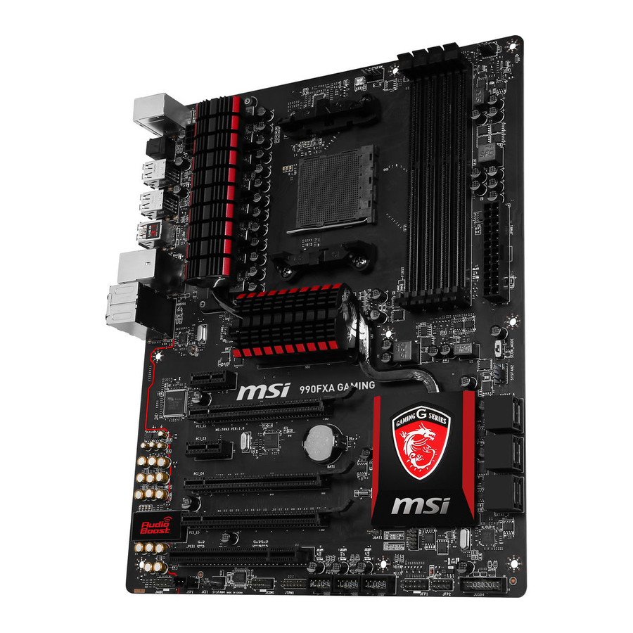
Chapter 1 Getting Started Thank you for choosing the 990FXA GAMING Series (MS-7893 v1.X) ATX motherboard. The 990FXA GAMING Series motherboards are based on 990FX & SB950 chipset for optimal system efficiency. Designed to fit ® the advanced AMD AM3/ AM3+ processor, the 990FXA GAMING Series ®... -
Page 3: Packing Contents
Packing Contents Drivers & Utilities Motherboard I/O Shield Motherboard Disc User Guide SLI Cable SATA Cable * These pictures are for reference only and may vary without notice. * The packing contents may vary according to the model you purchased. -
Page 4: Assembly Precautions
Assembly Precautions ■ The components included in this package are prone to damage from electrostatic discharge (ESD). Please adhere to the following instructions to ensure successful computer assembly. ■ Always turn off the power supply and unplug the power cord from the power outlet before installing or removing any computer component. -
Page 5: Motherboard Specifications
Motherboard Specifications CPU Support ■ Supports AMD / Phenom II/ Athlon II and Sempron ® processors for the AM3/ AM3+ socket Hypertransport ■ HyperTransport™ 3.0, supports up to 5.2 GT/s Chipset ■ AMD 990FX & SB950 ® Memory ■ 4x DDR3 memory slots supporting up to 32GB ■... - Page 6 ■ Fast Boot ■ GAMING APP ■ Super Charger ■ Live Update 6 ■ M-Flash Software ■ Drivers ■ MSI - Command Center - Live Update 6 - Fast Boot ■ 7-ZIP ■ Sound Blaster Cinema 2 ■ Killer Network Manager ■...
-
Page 7: Connectors Quick Guide
Connectors Quick Guide DIMM4 DIMM3 JPWR2 SYSFAN3 DIMM2 DIMM1 SYSFAN1 CPUFAN CPU Socket Back Panel JPWR1 SLOW_MODE PCI_E1 SYSFAN2 PCI_E2 SATA5_6 PCI_E3 SATA3_4 PCI_E4 SATA1_2 PCI_E5 JBAT1 PCI1 JCI1 JCOM1 JFP2 JFP1 JAUD1 JTPM1 JUSB4 SYSFAN4 JUSB3 JUSB1 JSP1 JUSB2... -
Page 8: Connectors Reference Guide
Connectors Reference Guide Port Name Port Type Back Panel I/O Ports AM3/ AM3+ Socket CPUFAN,SYSFAN1~4 Fan Power Connectors DIMM1~4 DDR3 Memory slots JAUD1 Front Panel Audio Connector JBAT1 Clear CMOS Jumper JCI1 Chassis Intrusion Connector JCOM1 Serial Port Connector JFP1, JFP2 System Panel Connectors JPWR1~2 ATX Power Connectors... -
Page 9: Back Panel Quick Guide
Back Panel Quick Guide PS/2 Keyboard/ LAN Port Mouse combo Port Line-In RS-Out USB 2.0 Port USB 2.0 Port USB 3.1 Port Optical S/PDIF-Out Line-Out CS-Out SS-Out USB 2.0 Port USB 2.0 Port ▶ PS/2 Keyboard/ Mouse combo Port The PS/2 keyboard/ mouse DIN connector for PS/2 keyboard/ mouse. - Page 10 ▶ Audio Ports These connectors are used for audio devices. ■ Line in: Used for connecting external audio outputting devices. ■ Line out: Used as a connector for speakers or headphone. ■ Mic: Used as a connector for a microphone. ■...
- Page 11 This motherboard is designed to support overclocking. Before attempting to overclock, please make sure that all other system components can tolerate overclocking. Any attempt to operate beyond product specifications is not recommend. MSI does not guarantee the damages or risks caused by inadequate operation beyond product...
-
Page 12: Cpu & Cooler Installation
CPU & Cooler Installation When you are installing the CPU, make sure the CPU has a cooler attached on the top to prevent overheating. Meanwhile, do not forget to apply some thermal paste on CPU before installing the heat sink/cooler fan for better heat dispersion. Follow the steps below to install the CPU &... - Page 13 5. Locate the CPU fan connector on the motherboard. 6. Position the cooling set onto the retention mechanism. Hook one end of the clip to hook first. CPU fan connector 7. Then press down the other end of the clip to fasten the cooling set on the top of the retention mechanism.
-
Page 14: Dual-Channel Mode Population Rule
Memory These DIMM slots are used for installing memory modules. DIMM1 DIMM2 DIMM3 DIMM4 Dual-Channel mode Population Rule In Dual-Channel mode, the memory modules can transmit and receive data with two data bus channels simultaneously. Enabling Dual-Channel mode can enhance system performance. -
Page 15: Mounting Screw Holes
Mounting Screw Holes When installing the motherboard, first install the necessary mounting stands required for an motherboard on the mounting plate in your computer case. If there is an I/O back plate that came with the computer case, please replace it with the I/O backplate that came with the motherboard package. -
Page 16: Jpwr1~2: Atx Power Connectors
JPWR1~2: ATX Power Connectors These connectors allow you to connect an ATX power supply. To connect the ATX power supply, align the power supply cable with the connector and firmly press the cable into the connector. If done correctly, the clip on the power cable should be hooked on the motherboard’s power connector. -
Page 17: Pci_E1~5: Pcie Expansion Slots
Expansion Slots This motherboard contains numerous slots for expansion cards, such as discrete graphics or audio cards. PCI_E1~5: PCIe Expansion Slots The PCIe slot supports the PCIe interface expansion card. PCIe x16 Slot PCIe x1 Slot PCI1: PCI Expansion Slot The PCI slot supports additional LAN, SCSI, USB, and other add-on cards that comply with PCI specifications. -
Page 18: Video/ Graphics Cards
Adding on one or more discrete video cards will significantly boost the system’s graphics performance. For best compatibility, MSI graphics cards are recommended. Single Video Card Installation 1. -
Page 19: Internal Connectors
Internal Connectors SATA1~6: SATA Connectors This connector is a high-speed SATA interface port. Each connector can connect to one SATA device. SATA devices include disk drives (HDD), solid state drives (SSD), and optical drives (CD/ DVD/ Blu-Ray). SATA6 SATA4 SATA2 SATA5 SATA3 SATA1... -
Page 20: Cpufan,Sysfan1~4: Fan Power Connectors
CPUFAN,SYSFAN1~4: Fan Power Connectors The fan power connectors support system cooling fans with +12V. If the motherboard has a System Hardware Monitor chipset on-board, you must use a specially designed fan with a speed sensor to take advantage of the CPU fan control. Remember to connect all system fans. -
Page 21: Jfp1, Jfp2: System Panel Connectors
JFP1, JFP2: System Panel Connectors These connectors connect to the front panel switches and LEDs. When installing the front panel connectors, please use the optional M-Connector to simplify installation. Plug all the wires from the computer case into the M-Connector and then plug the M- Connector into the motherboard. -
Page 22: Jusb1~3: Usb 2.0 Expansion Connectors
JUSB1~3: USB 2.0 Expansion Connectors This connector is designed for connecting high-speed USB peripherals such as USB HDDs, digital cameras, MP3 players, printers, modems, and many others. Important Note that the VCC and GND pins must be connected correctly to avoid possible damage. -
Page 23: Jci1: Chassis Intrusion Connector
JCI1: Chassis Intrusion Connector This connector connects to the chassis intrusion switch cable. If the computer case is opened, the chassis intrusion mechanism will be activated. The system will record this intrusion and a warning message will flash on screen. To clear the warning, you must enter the BIOS utility and clear the record. -
Page 24: Jcom1: Serial Port Connector
JCOM1: Serial Port Connector This connector is a 16550A high speed communication port that sends/receives 16 bytes FIFOs. You can attach a serial device. JAUD1: Front Panel Audio Connector This connector allows you to connect the front audio panel located on your computer case. - Page 25 Jumper JBAT1: Clear CMOS Jumper There is CMOS RAM onboard that is external powered from a battery located on the motherboard to save system configuration data. With the CMOS RAM, the system can automatically boot into the operating system (OS) every time it is turned on. If you want to clear the system configuration, set the jumpers to clear the CMOS RAM.
-
Page 26: Slow_Mode: Slow Mode Booting Switch
Switch SLOW_MODE: Slow Mode Booting Switch This switch is used for LN2 cooling solution, that provides the extreme overclocking conditions, to boot at a stable processor frequency and to prevent the system from crashing. Enabled Normal (Default) Important Users will try extreme low temperature overclocking at their own risks. The overclocking results will vary according to the CPU version. -
Page 27: Drivers And Utilities
After you install the operating system you will need to install drivers to maximize the performance of the new computer you just built. MSI motherboard comes with a Driver Disc. Drivers allow the computer to utilize your motherboard more efficiently and take advantage of any special features we provide. - Page 28 Chapter 2 Quick Installation...
-
Page 29: Cpu Installation
CPU Installation... -
Page 31: Memory Installation
Memory Installation... -
Page 32: Motherboard Installation
Motherboard Installation... -
Page 34: Power Connectors Installation
Power Connectors Installation... -
Page 36: Sata Hdd Installation
SATA HDD Installation... -
Page 37: Front Panel Connector Installation
Front Panel Connector Installation JFP1 Connector Installation Front Panel Audio Connector Installation... -
Page 38: Peripheral Connector Installation
Peripheral Connector Installation USB2.0 Connector Installation USB3.0 Connector Installation... -
Page 39: Graphics Card Installation
Graphics Card Installation... -
Page 41: Bios Setup
Chapter 3 BIOS Setup CLICK BIOS is a revolutionary UEFI interface that allows you to setup and configure your system for optimum use. Using your mouse and keyboard, users can change BIOS settings, monitor CPU temperature, select the boot device priority and view system information such as the CPU name, DRAM capacity, the OS version and the BIOS version. -
Page 42: Entering Bios Setup
(optional) on the motherboard to enable the system going to BIOS setup directly at next boot. Click "GO2BIOS" tab on "MSI Fast Boot" utility screen. Important Please be sure to install the “MSI Fast Boot” utility before using it to enter the BIOS setup. - Page 43 Overview After entering BIOS, the following screen is displayed. Temperature monitor Language System information Virtual OC Genie Button Boot device priority bar BIOS menu selection BIOS menu selection Menu display ▶ BIOS menu selection The following options are available: ■ SETTINGS - Uses this menu to specify the parameters for chipset and boot devices.
- Page 44 Enables or disables the OC Genie function by clicking on this button. When enabled, this button will be light. Enabling OC Genie function can automatically overclock with MSI optimized overclocking profile. Important We recommend that you do not to make any modification in OC menu mode and do not to load defaults after enabling the OC Genie function.
-
Page 45: Operation
Operation You can control BIOS settings with the mouse and the keyboard. The following table lists and describes the hot keys and the mouse operations. Hot key Mouse Description <↑↓→← > Select Item Move the cursor <Enter> Select Icon/ Field Click/ Double-click the left button <Esc>... -
Page 46: System Status
SETTINGS System Status ▶ System Date Sets the system date. Use tab key to switch between date elements. The format is <day> <month> <date> <year>. <day> Day of the week, from Sun to Sat, determined by BIOS. Read-only. <month> The month from Jan. through Dec. <date>... - Page 47 Advanced ▶ PCI Subsystem Settings Sets PCI Express interface protocol and latency timer. Press <Enter> to enter the sub-menu. ▶ PCI Latency Timer [32] Sets latency timer of PCI interface device. [Options: 32, 64, 96, 128, 160, 192, 224, 248 PCI Bus clocks] ▶...
- Page 48 ▶ SATA Mode [AHCI Mode] Sets the operation mode of the onboard SATA controller. The default mode is AHCI. [Disabled] Disables the SATA function. [IDE Mode] Specify the IDE mode for SATA storage devices. [AHCI Mode] Specify the AHCI mode for SATA storage devices. AHCI (Advanced Host Controller Interface) offers some advanced features to enhance the speed and performance of SATA storage device, such as Native Command Queuing (NCQ) and hot-plugging.
- Page 49 Disables this function. ▶ MSI Fast Boot [Disabled] MSI Fast Boot is the fastest way to boot the system. It will disable more devices to speed up system boot time which is faster than the boot time of “Fast Boot” .
- Page 50 Important If you want to enter BIOS with enabled “MSI Fast Boot” mode or enabled "Fast Boot" mode, you have to click the "GO2BIOS" tab on MSI Fast Boot utility screen or press the "GO2BIOS" button (optional) on the motherboard. And then the system will enter to BIOS setup directly at next boot.
- Page 51 ▶ Resume From S3/S4/S5 by PS/2 Keyboard [Disabled] Disables or enables the system wake up by PS/2 keyboard. [Any Key] Enables the system to be awakened from S3/ S4/ S5 state when activity of any key on PS/2 keyboard is detected. [Hot Key] Enables the system to be awakened from S3/ S4/ S5 state when activity of hot key on PS/2 keyboard is detected.
- Page 52 ▶ U-Key Enable or disable USB driver device as key. This requires the USB device to be plugged in for access to the computer.. ▶ Make U-Key at When the “U-Key” as sets to [Enabled], this item is selectable. This item allows you to specify the USB drive.
- Page 53 Important • Overclocking your PC manually is only recommended for advanced users. • Overclocking is not guaranteed, and if done improperly, can void your warranty or severely damage your hardware. • If you are unfamiliar with overclocking, we advise you to use OC Genie for easy overclocking.
- Page 54 ▶ AMD Turbo Core Technology [Auto] Based on AMD Turbo Core Technology, part of CPU core ratio may pop down for providing more performance headroom for active CPU core, even AMD Cool’n’Quiet Technology is Disabled. [Auto] Turbo Core Technology will linked to AMD Cool’n’Quiet Technology. [Enabled] Enables this function.
- Page 55 ▶ HT Link Speed This item allows you to set the Hyper-Transport Link speed. Setting to [Auto], the system will detect the HT link speed automatically. ▶ Adjusted HT Link Frequency It shows the adjusted HT Link frequency. Read-only. ▶ HT Link Control Press <Enter>...
- Page 56 ▶ MEMORY-Z Press <Enter> to enter the sub-menu. This sub-menu displays all the settings and timings of installed memory. ▶ CPU Features Press <Enter> to enter the sub-menu. ▶ AMD Cool’n’Quiet [Auto] Enabled or disabled AMD Cool’n’Quiet function. [Auto] Depends on AMD Design. [Enable] Enables AMD Cool’n’Quiet function.
- Page 57 M-FLASH Important M-Flash funcion allows you to update BIOS from USB flash disk (FAT32/ NTFS format only). ▶ Save BIOS to storage Saves the current BIOS file to the USB flash disk. The USB flash disk drive should be in FAT32 format. ▶...
- Page 58 OC PROFILE ▶ Overclocking Profile 1/ 2/ 3/ 4/ 5/ 6 Overclocking Profile 1/ 2/ 3/ 4/ 5/ 6 management. Press <Enter> to enter the sub- menu. ▶ Set Name for Overclocking Profile 1/ 2/ 3/ 4/ 5/ 6 Names the current overclocking profile. ▶...
-
Page 59: Hardware Monitor
HARDWARE MONITOR Current Temperature & Temperature & Speed Speed information graphic display control field Voltage display ▶ Current Temperature & Speed information Shows the current CPU temperature, system temperature and fans' speeds. ▶ Temperature & Speed graphic display The red graph shows the minimum and maximum temperatures that be set on the “Fan control field”. - Page 60 Please follow the description below to set the temperatures and fan speeds. ■ a - Selects a fan you want to specify the speed. ■ b - Checks this item to activate the following items for changing default values. ■ c - Slides the Min and Max tabs to set the minimum and maximum temperatures.
-
Page 61: Realtek Audio
Appendix A Realtek Audio The Realtek audio provides 10-channel DAC that simultaneously supports 7.1 sound playback and 2 channels of independent stereo sound output (multiple streaming) through the Front-Out-Left and Front-Out-Right channels. -
Page 62: Software Configuration
Software Configuration After installing the audio driver (see Chapter 1 - Driver and Utilities), the “Realtek HD Audio Manager” icon will appear at the notification area (lower right of the screen). You may double click the icon and the GUI will pop up accordingly. double click the icon It is also available to enable the audio driver by clicking the Realtek HD Audio Manager from the Control Panel. -
Page 63: Auto Popup Dialog
▶ Device Selection Here you can select a audio output source to change the related options. The “check” sign indicates the devices as default. ▶ Volume Adjustment You can control the volume or balance the right/left side of the speakers that you plugged in front or rear panel by adjust the bar. -
Page 64: Hardware Default Setting
Hardware Default Setting The following diagrams are audio back panel default setting. ■ Backpanel audio jacks to 2-channel speakers diagram F r o ■ Backpanel audio jacks to 4-channel speakers diagram F r o R e a... - Page 65 ■ Backpanel audio jacks to 6-channel speakers diagram F r o C e n R e a t e r & S u b w o o f ■ Backpanel audio jacks to 8-channel speakers diagram F r o C e n R e a t e r &...
- Page 66 Appendix B AMD RAID This appendix will assist users in configuring and enabling RAID functionality.
-
Page 67: Raid Configuration
RAID Configuration Creating and deleting RAID set and performing other RAID setting up operations are done in the RAID BIOS. During boot-up, a screen similar to the one below will appear for about few seconds. Press <Ctrl-F> to enter RAID Option ROM utility. Press <Ctrl-F>... - Page 68 View Drives Assignments This window displays the model number, capacities and assignment of the drives physically attached to the SATA host adapter.
- Page 69 LD View / LD Define Menu (Creating RAID) The selection of the RAID configuration should be based upon factors including performance, data security, and the number of drives available. It is best to carefully consider the long-term role of the system and plan the data storage strategy. RAID sets can be created either automatically, or to allow the greatest flexibility, manually.
- Page 70 ■ Stripe Block Size, the default 64KB is best for most applications. RAID 0 or 10 only. ■ Gigabyte Boundary, allows use of slightly smaller replacement drives. 3. On the Drives Assignments window, use the arrow key to choose the hard drives which you want to make part of the LD, use the space key to change the assignment to “Y”.
- Page 71 6. The message will show up on the bottom, press any key to use maximum capacity or press [Ctrl-Y] to modify array capacity manually. Important • The default capacity is the full capacity of the selected hard drives. • If you allocate the first LD capacity manually, you can create second LD with remaining capacity of the selected hard drives.
- Page 72 Delete LD Menu (Deleting RAID) 1. Press “3” on the main to enter the Delete LD Menu. 2. Choose a LD No. you want to delete and press [Del] or [Alt+D] delete the RAID set. 3. On the next screen, a message will display to inform you, press “Ctrl+Y” to delete the RAID set or other key to abort it.
-
Page 73: Installing Driver
Please follow the instruction below to make an “AMD RAID Driver” for yourself. ® • Insert the MSI Driver Disc into the optical drive. • Click the “Browse CD” on the Setup screen. • Copy all the contents in - ChipSet\W7_W8\Packages\Drivers\SBDrv\SB9xx\RAID •... -
Page 74: Installing Os On 2.2Tb Raid
Installing OS on 2.2TB RAID If you plan to install 64bit operating system on a RAID volume greater than 2.2TB, you can only manually create and load the RAID array in EFI shell. WARNING Create raid array will erase all the data stored on hard drives! Make sure to back up your files! There is no way to reverse the process! The following describes an example of how to install Windows 7/ 8 64bit on a RAID 0 volume greater than 2.2TB. - Page 75 9. Delete all logical drivers by selecting “Logical Driver Main Menu” → “Logical Driver Delete Menu”. + Logical Drive Main Menu + Logical Drive List Menu + Logical Drive Create Menu + Logical Drive Delete Menu 10. Make sure there are not any logical drivers (as shown below). + Logical Drive Delete Menu - <Not Found Any Logical Drive>...
- Page 76 14. Back to “Logical Driver Main Menu” and fill “Ld Name”. + Logical Drive Create Menu + Usable Physical Drive List + Basic Setting - Raid Mode <RAID 0> - Stripe Block (KB) <64> - Initialization <Fast> - Gigabyte Boundary : <Enable>...
- Page 77 USB 2.0 port (not USB 3.0 port) and click Browse. Important You can find the AMD RAID driver from MSI Driver Disc. The path is \\ChipSet\RICHLAND_W7_W8\Packages\Drivers\SBDrv\hseries\RAID Please copy all the files in the folder to a USB flash drive.
- Page 78 23. Select “Removable Disk” from Browse for Folder dialog then click OK. 24. Install “AMD AHCI Compatible RAID Controller”. 25. Windows 7/ 8 64bit can find the RAID volume now. Please continue the installing procedure.
Need help?
Do you have a question about the 990FXA GAMING and is the answer not in the manual?
Questions and answers