
Related Manuals for Community XLT


Summary of Contents for Community XLT
- Page 1 XLT / XLTE XLT / XLTE XLT / XLTE XLT / XLTE FULL-RANGE SYSTEMS FULL-RANGE SYSTEMS FULL-RANGE SYSTEMS FULL-RANGE SYSTEMS SUBWOOFERS SUBWOOFERS SUBWOOFERS SUBWOOFERS Owner’s Manual...
-
Page 3: Community Professional Loudspeakers
First to publish AudioCAD data on CD-ROM. First professional audio company with an Internet web site – http://www.loudspeakers.net First compact, weather-resistant, full-range horn systems - R2 Series. First custom configurable outdoor systems - WET Series PAGE Community XLT / XLTE Series Owner’s Manual... -
Page 4: Ec Statement Of Conformity
The responsible manufacturer is the company: Community Light & Sound, Inc. 333 East 5th Street Chester, PA 19013 Tel: 610 876-3400 Fax: 610 874-0190 e-mail: info@loudspeakers.net Chester, PA USA Oct 1999 PAGE Community XLT / XLTE Series Owner’s Manual... -
Page 5: Table Of Contents
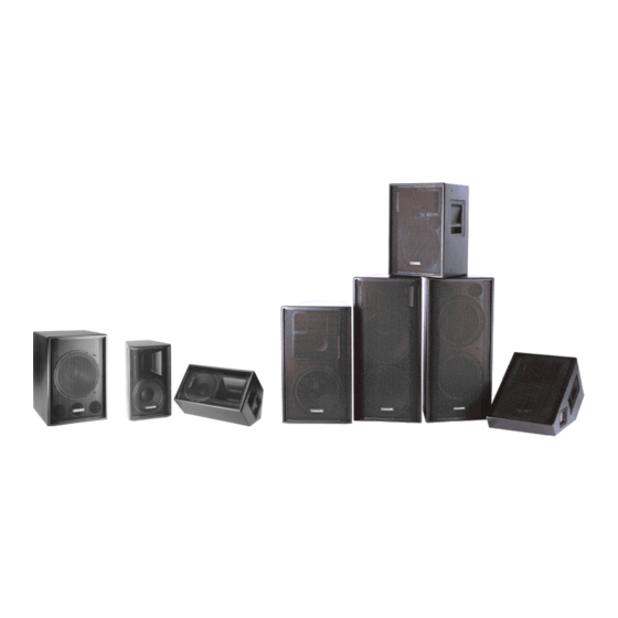
Table 5: Recommended Amplifier Power for Subwoofers ...17 Table 6: Loudspeaker Wire Selection ...20 Table 7: Minimum Impedance for two XLT or XLTE Loudspeakers in Parallel...22 (Front Cover L to R: 51, 42, 41, 46, 47, 43, 55, 48. XLTE models shown.) -
Page 6: Introduction And Safety Information
MODEL NUMBER USAGE IN THIS MANUAL Within this manual XLT and XLTE models are generally referred to only by their numerical suffixes. For example, model ‘43’ refers to both the XLT43 and XLT43E. Where information applies only to a specific model, such as only to the XLT46 but not the XLT46E, the complete model number is used. -
Page 7: Unpacking And Inspection
UNPACKING AND INSPECTION The Community XLT and XLTE loudspeakers are inherently rugged and are carefully packed in well-designed cartons. It is a good idea to inspect the unit carefully after it has been removed from the packaging, as sometimes there is hidden damage due to some unfortunate incident in shipment. -
Page 8: Quick Start-Up -- Passive Mode Or Subwoofer
NOTES: As shipped from the factory the PASSIVE/BIAMP switch is set for PASSIVE mode and the HF Level Switch (not shown) is set in the +4 dB (maximum) position. Subwoofer input panel layout is different from that shown. PAGE Community XLT / XLTE Series Owner’s Manual... -
Page 9: Quick Start-Up -- Biamp Mode
NOTE: As shipped from the factory the PASSIVE/BIAMP switch is set for PASSIVE mode and the HF Level Switch (not shown in this drawing) is set in the +4 dB (maximum) position. PAGE Community XLT / XLTE Series Owner’s Manual... -
Page 10: Fig 1: Physical Features
Figure 1: Physical Features NOTE: These are composite, generalized drawings showing features for both XLT and XLTE products. Refer to TABLE 1 to determine which of these features apply to your particular loudspeaker model. PAGE Community XLT / XLTE Series Owner’s Manual... -
Page 11: Physical Features
" XLT55E FEATURES DESCRIPTIONS This chart describes the physical features for XLT and XLTE. Because not all features apply to all models, refer to FIGURE 1 and TABLE 1 Matrix to determine which features apply to which products. MOUNTING POINTS... - Page 12 Heavy-duty rubber feet. Installed by user on the XLT41E. Community logo recessed into grille. Community XLT / XLTE Series Owner’s Manual 1-1/2 in. / 38 mm #6 Accept NL4FC in-line...
-
Page 13: Community Xlt And Xlte Series General Description
COMMUNITY XLT™ AND XLTE™ SERIES GENERAL DESCRIPTION The XLT loudspeaker systems have features and functions designed primarily for portable applications. The XLTE systems are suitable for both heavier-duty portable use and for permanent installation. From the smallest to the largest model, these loudspeakers represent Community’s commitment to meeting the audio requirements for sound reinforcement with performance, quality, and reliability at affordable prices. - Page 14 Ferrofluid Cooling All XLT and XLTE low frequency drivers and the 46 mid frequency driver are specifically designed to be Ferrofluid- cooled. Ferrofluid is a viscous liquid that is attracted by magnetic fields. The liquid is injected into the voice coil gap during manufacturing and is permanently retained by the magnetism in the gap.
-
Page 15: Power Handling
ENCLOSURES XLT: These enclosures are constructed of OSB (Oriented Strand Board). This wood is a type of composite board specially constructed with the wood grains oriented in one direction. This results in a much stronger material for a given weight than other types of composite wood materials. - Page 16 Each enclosure has provisions for permanently installing it. XLT: These models have four 5/16-18 threaded T-nuts - one each in the top, sides, and bottom. The XLT48 has two mounting points - one on each of the two sides. These points are designed to be used with Community’s optional CSSUPKIT or WB1 mounting kits for permanent installations.
- Page 17 The straps have a series of 3/8 in. / 9.5 mm diameter holes for attachment to rigging. WB1 – Two steel brackets that can be attached to the T-nuts on XLT and XLT48E models. Used for mounting to walls or ceilings.
-
Page 18: Setup And Operation
Recommended Amplifier Power for Specific Models TABLES 3, 4, and 5 list the recommended amplifier power for all of the XLT and XLTE models. The power figures listed indicate amplifier RMS ratings and assume this a 20 Hz – 20 kHz power rating per amplifier channel. -
Page 19: System Configurations
Table 5: Recommended Amplifier Power for Subwoofer SYSTEM CONFIGURATIONS FIGURE 2 and FIGURE 3 show the possible configurations for the XLT and XLTE loudspeakers and subwoofers. FIGURE 2 shows the possible configurations when your full-range system is operated in PASSIVE mode both with and without an XLT or XLTE subwoofer. -
Page 20: Fig 2: Passive Mode Configurations
If you have a choice of filter types, the Butterworth type should work well. Adjust the acoustical balance between the full-range loudspeaker and the subwoofer by using the amplifier input level controls or the crossover output level controls. FIGURE 2: PASSIVE Mode Configurations PAGE Community XLT / XLTE Series Owner’s Manual... -
Page 21: Fig 3: Biamp Mode Configurations
FIGURE 3: BIAMP Mode Configurations PAGE Community XLT / XLTE Series Owner’s Manual... -
Page 22: Electrical Installation
THHN or THWN available in hardware stores and electrical supply houses. INPUT JACKS (See SECTION 6.4 for proper wiring of the connectors) The XLT and XLTE loudspeakers have jacks that accept two types of connectors: Neutrik Speakons and 1/4 in. tip/sleeve plugs. PAGE... - Page 23 The following table lists the nominal impedance for two of the various models loudspeakers operated in parallel. The amplifier must be rated to drive this impedance. If you examine the minimum impedances listed in the specifications PAGE Community XLT / XLTE Series Owner’s Manual...
-
Page 24: Connecting The Loudspeakers
2 x 48 2 x 51 2 x 55 Table 7: Nominal Impedances for Two XLT or XLTE Loudspeakers In Parallel CONNECTING THE LOUDSPEAKERS The following diagrams show the wiring connections for the loudspeakers. Be sure to observe proper polarity when making the connections. -
Page 25: Connection Diagrams
OUTPUT is connected to the LF input on the full-range loudspeaker. For convenience, the 1/4 in. jack may be used for this connection. (See “Technical Note” in SECTION 6.2.2). Observe proper polarity when making connections. PAGE FIGURE 5: Wiring for BIAMP Mode Full-Range FIGURE 6: Wiring for Subwoofer Community XLT / XLTE Series Owner’s Manual... -
Page 26: Physical Installation
The grille is purposely tight fitting to prevent the metal from resonating so it may require some force to pull it away. Be careful not to catch the carpet pile with the edges on the XLT models. Do not loose any of the grille standsoffs To reinstall the grille, make sure that the grille is correctly oriented so that holes in the grille line up with all of the standoffs that should be positioned in their recesses. -
Page 27: Mounting And Rigging
IMPORTANT NOTE: Mounting/Rigging Point Holes All mounting/rigging points, T-nut mounting points, and stand adapter points for all XLT and XLTE loudspeakers must either be used for mounting hardware or remain plugged with the supplied screws. If they are not plugged up, these points can create air leaks in the enclosure that will compromise the LF performance with reduced output and/or distortion. -
Page 28: Fig 7: Mounting Point Detail - Pull Direction
Refer to the instructions packed with the CSSUPKIT for proper application and use. PAGE FIGURE 7: Mounting Point Detail - Pull Direction FIGURE 8: XLT Mounting Points Community XLT / XLTE Series Owner’s Manual... -
Page 29: Fig 9: Xlte Mounting Points
Stand Bracket Inserts (46 and 48 only) For pole or stand mounting, XLT and XLTE models 46 and 48 have two 5/16-18 threaded inserts (T-nuts) on the bottom of the 46 and top of the 48. They are spaced 5.5 in. / 140 mm apart to mate with an Ultimate Support BMB- 200K stand bracket or similar hardware. -
Page 30: Stacking Enclosures
This can put the full-range loudspeaker at or above the audience’s ear level to provide greater projection of sound to the rear of the audience. Both the XLT and XLTE enclosures have provisions to help prevent the top enclosure from moving around due to sound vibrations or from sliding off if accidentally bumped. -
Page 31: Acoustical Adjustments
Ohms or higher) or a piezo-electric tweeter and listen for noticeable distortion at the output of each piece of equipment. This point will be just above the maximum output. Without some method of determining the maximum output on each piece of equipment, you cannot expect to optimize the gain structure. PAGE Community XLT / XLTE Series Owner’s Manual... - Page 32 8.2.2 Residual Noise XLT and XLTE loudspeakers have high sensitivities. This means that they produce a relatively high volume of sound for a given electrical input. This also includes the residual electronic noise of an audio system. By setting gain structure properly and using high quality, professional electronics with balanced connections, this noise should be at or near inaudibility.
- Page 33 Noise should not be audible and you should be able to drive the amplifier to its maximum output on normal program material with no significant distortion or other undesirable sounds. PAGE Use this switch to voice the loudspeaker for different Community XLT / XLTE Series Owner’s Manual...
-
Page 34: Operating Precautions
POWERSENSE DDP All XLT and XLTE loudspeakers and subwoofers incorporate PowerSense DDP (Dynamic Driver Protection) circuitry that automatically provides thermal and over-current protection for the individual drivers. This provides significant but not absolute protection from damage. -
Page 35: Fig 11: Effects Of Amplifier Clipping
Judicious application of this type of equalization can make a loudspeaker sound significantly louder than it actually is. Both your listeners and your loudspeakers will thank you. PAGE FIGURE 11: Amplifier Clipping Community XLT / XLTE Series Owner’s Manual... -
Page 36: Fig 12: Sound Exposure Limits
RMS rating and do not test at this 25% level for more than a few moments. If test signals must be used for extended periods of time, the power input to the loudspeaker should be kept below 10% of the loudspeaker’s RMS rating to ensure the loudspeaker will not be damaged. PAGE Community XLT / XLTE Series Owner’s Manual... -
Page 37: Servicing The Loudspeaker
Molex plug is keyed so it can be inserted only in one direction. It will plug in easily when properly oriented. Ensure that it is fully seated into the receptacle on the crossover board. PAGE Community XLT / XLTE Series Owner’s Manual When... -
Page 38: Technical Specifications
Driver has as 2” diameter diaphragm and 1” exit. Dimensions are for XLT models including corners. XLTE dimensions will vary up to approximately +/- 0.5 in. (+/- 13 mm) from those listed. Model 42 is correct because it is only available as part of the XLTE Series. - Page 39 3 DDP = Dynamic Driver Protection. 4 Driver has as 2” diameter diaphragm and 1” exit. 5 Dimensions are for XLT models including corners. XLTE dimensions will vary up to approximately +/- 0.5 in. (+/- 13 mm) from the listed dimensions.
-
Page 40: In Case Of Difficulty
If distorted or no sound is heard from either or both drivers, either the drivers or crossover may not be working properly. Replace as needed. Community XLT / XLTE Series Owner’s Manual Please refer to Loose objects simply lying... - Page 41 1+ / 1- on the Neutrik connector. Check that the HF amplifier is turned on and that loudspeaker is properly connected to the amplifier. Community XLT / XLTE Series Owner’s Manual This can also damage your...
- Page 42 If this balance is not suitable then separate amplifiers for the subwoofer and full-range loudspeaker are recommended. The acoustic balance can then be adjusted using the amplifier input level controls. See symptoms for subwoofers. Community XLT / XLTE Series Owner’s Manual...
-
Page 43: Warranty Information And Service
CSX-S2 Loudspeaker Systems are covered by this warranty for a period of ten years in the USA, five years worldwide. XLT, XLTE, CPL, and CSV Loudspeaker Systems, fiberglass components and all mounting kits are covered by this warranty for a period of five years. - Page 44 WARRANTY INFORMATION AND SERVICE FOR COUNTRIES OTHER THAN THE USA To obtain specific warranty information and available service locations for countries other than the United States of America, contact the authorized Community Distributor for your specific country or region. PAGE Community XLT / XLTE Series Owner’s Manual...
-
Page 45: Specifications
NOMINAL COVERAGE ENCLOSURE FINISH 90° x 40° 90° x 40° 90° x 40° 60° x 40° 60° x 40° 60° x 40° Community XLT / XLTE Series Owner’s Manual GRILLE CLOTH Black Paint None White Paint White Unfinished Brown Black Paint... -
Page 46: Index
Mounting Point Holes ...25 Mounting Points...25 Neutrik Speakon Input Jacks ...21 Noise ...30 Operating Precautions ...32 Optional Accessories ...15 Parallel Load Impedances...21 Paralleling Loudspeakers...21 Passive / Biamp Switch ...12 Passive Mode ...32 Passive Mode ...6, 12 Community XLT / XLTE Series Owner’s Manual... - Page 47 XLT41E Horn Position... 15 XLT42E Horn Orientation... 25 XLT46 / XLT46E Midrange ... 11 XLT46 / XLT46E Horn Orientation ... 25 XLT48E Additional Models ... 43 XLTE Feet ... 14 XLTE Mounting/Rigging Points... 27 Community XLT / XLTE Series Owner’s Manual...
- Page 52 333 East 5 Street, Chester, PA 19013-4511 Phone (610) 876-3400 Fax (610) 874-0190 http://www.loudspeakers.net © 1999 Community Light & Sound, Inc. 991015Cm...
Need help?
Do you have a question about the XLT and is the answer not in the manual?
Questions and answers