Advertisement
Quick Links
FT & SUPER SIX
FINE TURF CASSETTE MOWER
INSTRUCTION MANUAL
DENNIS, Ashbourne Road, Kirk Langley, Derby, DE6 4NJ, United Kingdom
Telephone:- 01332 824777
Fax:- 01332 824 525
E-mail:- sales@dennisuk.com
E-mail:- spares@dennisuk.com
SP20001_REV_4
www.dennisuk.com
04/12
Advertisement

Related Manuals for Dennis FT430


Summary of Contents for Dennis FT430
-
Page 1: Instruction Manual
FT & SUPER SIX FINE TURF CASSETTE MOWER INSTRUCTION MANUAL DENNIS, Ashbourne Road, Kirk Langley, Derby, DE6 4NJ, United Kingdom Telephone:- 01332 824777 Fax:- 01332 824 525 E-mail:- sales@dennisuk.com E-mail:- spares@dennisuk.com SP20001_REV_4 www.dennisuk.com 04/12... - Page 3 MAKE A NOTE OF THE SERIAL NUMBERS OF YOUR MACHINE & ENGINE AND ALWAYS NOTE QUOTE THEM IN ANY COMMUNICATION WITH PERSONNEL AT DENNIS. The reliability and quality of performance of the depends upon some simple care maintenance carried out regularly.
- Page 4 General Lubrication ..............................15 - 16 Storage ....................................16 Guide to Replacement Parts .............................. 16 Guide To Cassette Use ............................... 17 Parts Listings ................................18 - 39 Model FT430 FT510 FT610 A - Width (mm) B - Length with Grassbox (mm) 1592...
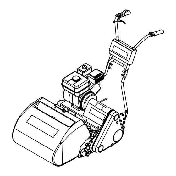
- Page 5 Manufactured with a 17” (43cm) 20” (51cm) or 24” (61cm) cutting width this mower is powered by a 5.5 h.p. air cooled single cylinder four stroke petrol engine (3.5hp FT430) The rear roller is powered via a slipping brake band clutch situated on the right handlebar.
- Page 6 In order to operate the machine safely please follow these Health and Safety guidelines. READ THE INSTRUCTIONS CONTAINED IN THIS MANUAL WITH CARE. IF YOU ARE IN ANY DOUBT PLEASE ASK YOUR EMPLOYER OR CONTACT US DIRECT AT DENNIS. Be familiar with the controls and the proper use of the equipment.
- Page 7 BEFORE YOU OPERATE THIS MACHINE YOU MUST READ AND STUDY THIS MANUAL. IF YOU ARE IN ANY DOUBT PLEASE ASK YOUR EMPLOYER OR CONTACT US DIRECT. Before commencing ensure the turf is free from stones or other obstructions which may damage the cassette unit. Set the height of cut to the required level (see page 9) Check the engine.
- Page 8 Once the preparatory steps have been completed as outlined on page 7 the engine may be started. (See manufacturer operating manual for full details). 1) Switch on the fuel tap. 2) Switch the handlebar cut off switch to ON, or depress deadmans handle (Item 1) 3) Set the throttle control to a half open position.
- Page 9 Always stop the engine before adjusting the height of cut. Failure to do this may result in severe injury. dethatching / brushing, depends on the setting of the front roller in relation to the main frame of the machine. The Click system allows easy adjustment of the front roller postion each click representing a change of 0.5mm (0.020”).
- Page 10 For cutter cylinder cassettes (5 or 9 blade units). edge of the frame at a comfortable height. It is now possible to make adjustments in the machine without cassette removal should you prefer. CYLINDERS AND BOTTOM BLADES ARE SHARP, WEAR GLOVES TO PROTECT YOUR HANDS AND FINGERS.
- Page 11 The height of the Handle Bars can be adjusted to suit various operators. Follow the below instructions:- 1. Remove Bolt (Item 1) on both sides of the machine. 2. Select the require position out of the 3 available. 3. Replace the Bolt on both sides of the machine. Item 1 If using the grass box, place the two locating tabs (projecting from the grass box support plates) into the slots on the machine side plate.
- Page 12 To remove the cassette unit for maintenance or to exchange cassettes the following procedure should be followed:- 1) Unscrew the hand wheel of the retaining pin for about half-an-inch (13mm) until the pip end is inside the nut on the side frame. 2) Slide the cassette unit along the tie bars as far as it will go until the cutter nut and coupling is clear of the three pins in the driving coupling.
- Page 13 Area Maintenance First 4 Hours First Month / 20 Hours 3 Months / 50 Hours 6 Months / 100 Hours Engine Oil Check Level Engine Oil Change Check Condition / Air Filter Clean Spark Plug Change Quantity Capacity Electrode Gap Engine Model Oil Type Fuel Type...
- Page 14 The brake band assembly is mounted on the end of the rear axle spindle on the right hand side of the machine. The assembly comprises a cast iron drum inner member, which is stopped or braked with a lined steel brake band. This operates dry and no lubrication of any kind is required.
- Page 15 The centre section gear case chamber of the rear roller is an assembly in two halves and contains the epicyclic gear system, which runs in an oil bath. during the cutting season. If in every day use then a topping up charge of about one egg cup full every two months may be appropriate.
- Page 16 ENGINE NUMBER. A BOX TO ENTER THESE FOR EASY REFERENCE IS AT THE BEGINNING OF THE MANUAL. This manual contains listing of parts for the Dennis FT430, FT510 and FT610 machines. An illustration of the parts as an assembly is shown above the list.
- Page 17 Settings - Expressed as above and below ground level i.e. by placing the setting bar between the front and rear rollers, the top of the bar represents ground level. Used from ground +3mm to ground -3mm to control thatch, cutting lateral growths and standing up lying grasses ready for cutting and lifting with the comb.
- Page 18 229492 Retaining Plate Assy SP05010 Split Pin 1/8” x 1” 230004 Support Bracket SP03008 Washer M8 Form A 230006 Support Plate Engine 800104 Cassette Retaining Screw 800020 FT L.H. Side Plate Assembly 800021 FT R.H. Side Plate Assy J20222 Cork Buffer 800104 Stop Pin Assy J17235...
- Page 19 > 08/2010 J209253 Side Plate LH (FT) J209003 3 Groove Drive Belt (Rear Roller) J209218 Side Plate LH (Super Six) J209005 5 Groove Drive Belt (Cylinder) 229741 Buffer Block 229742 Buffer J209072 Chain Case Stud ( > 08/2010) J20216 Unit Limiting Stud J20238 Shoulded Gearing Stud (FT) J209110...
- Page 20 J209254 Side Plate RH (FT) 209219 Side Plate RH (Super Six) J20023 Unit Limiting Stud 229741 Buffer Block 229742 Buffer SP03003 Washer M6 Toothed SP01008 Hex Set Screw M6 x 16 J209229 Clutch Rod Stop J209078 Retaining Screw Plate SP01016 Button Head M6 x 12 J20207 Stud Brake Band Cover...
- Page 21 J209230 Dog Clutch Fork Assy. J179231 17” Clutch Control Rod J209231 20” Clutch Control Rod J249231 24” Clutch Control Rod J20017 Knob - Red J209024 Nut 5/16 BSF Lock (Thin) J209026 Nut 5/16 UNF Lock (Thin) J209019 Rod End J209232 Bracket Control Rod J209226 Clutch Fork Pivot Mounting...
- Page 22 800002 Front Roller Assy 17” 800502 Front Roller Assy 20” 800503 Front Roller Assy 24” J20522 End Block RH J20521 End Block LH 800149 Click Height Adjuster RH 800148 Click Height Adjuster LH 800182 Comb Bar Sub Assy 17” 800180 Comb Bar Sub Assy 20”...
- Page 23 J20235 20” Front Cross Bar J24235 24” Front Cross Bar J20292 Collar Front Tie Bar J20550 20” Front Roller J24550 24” Front Roller J20551 Scraper Bar Ear J20552 20” SS Scraper Bar J24552 24” SS Scraper Bar J209110 Unit Bearing Stud J209111 Bush Quadrant J209112...
- Page 24 J179237 FT430 Grassbox Moulding J209237 FT510 Grassbox Moulding J179237 FT610 Grassbox Moulding J209062 Mesh (FT510) J249062 Mesh (FT610) J17257 17” Grassbox Edging Strip J209063 20” Grassbox Edging Strip J249063 24” Grassbox Edging Strip J209064 Handle Plate Grass Box J209222 LH Grassbox Wing...
- Page 25 B32902 Decal Dennis J209074 Brake Band Cover Screw 194946 Chain Case Screw 228031 Belt Guard Seal 1.23m J20712 Belt Guard J20206 Brake Band Cover B32903 Decal Union Jack 228031 Brake Band Seal 0.62m FT & Super Six SP20001_REV_4...
- Page 26 Washer M10 Form G 229724 Arm Pivot Bush 229725 Pivot Arm Lower Handle 229726 Bush Handle Pivot 229736 Pivot Bolt B32902 Decal Dennis 230035 Handle Lower 17” W.A. 230020 Handle Lower 20” W.A. 230030 Handle Lower 24” W.A. 230040 Handle Upper W.A. 230487...
- Page 27 Cutter Engagment Assy (FT510) 228106 Washer M22 Form A See 2.01 Cutter Engagment Assy (FT610) J209245 Top Drive Bearing Housing (FT430) 800007 17” Top Drive Assembly J209211 Top Drive Bearing Housing (FT510 & 610) 1 800016 20” Top Drive Assembly 800041 24”...
- Page 28 229900 Engine (Honda GX120) 229901 Engine (Honda GX160) 800027 Flywheel Assembly 800026 Clutch Hub Assembly J209233 Stub Shaft 228102 Coupling Shaft (7/8”) J209025 Key (3/16” x 3/16” x 1 3/4”) J20467 Grub Screw (M8 x 8) J209006 Circlip (47 M1308-0470) J209247 Bearing 6906 2RS J209248...
- Page 29 See 8.02 Rear Roller Assy J20119 Spring Scraper Brake Band J20256 Roller Slot Cover Plate J20461 Brake Drum J20463 Brake Band Assy J209201 Rear Roller Driven Pulley SP03016 Washer M10 Form C SP02008 Nut M10 Nyloc J20462 Key Woodruff (606) 3/16” x 3/4” J20457 Key 3/16”...
- Page 30 See 8.05 RH Differential Assy See 8.04 LH Differential Assy See 8.03 Outer Roller Assy See 8.03 Outer Roller Assy J20477 LH Spacer Collar J20450 LH Bearing Housing J20454 Bearing R18 2RS J20475 Circlip Internal 54 x 2 J20474 Circlip Internal 57 x 2 J20455 Bearing RLS8 2RS J20467...
- Page 31 J179540 17” LH Outer Roller c/w Bush J179541 17” RH Outer Roller c/w Bush 800019L 20” LH Outer Roller c/w Bush 800019R 20” RH Outer Roller c/w Bush 800044L 24” LH Outer Roller c/w Bush 800044R 24” RH Outer Roller c/w Bush J20476 Plunger Bush J20435...
- Page 32 800005 Pinion Shaft Assy (FT430) 800014 Pinion Shaft Assy (FT510) 800039 Pinion Shaft Assy (FT610) J20400 Planet Gear Case J17401 17” Pinion Gear Case Tube J20401 20” Pinion Gear Case Tube J24401 24” Pinion Gear Case Tube J20405 Planet Gear Pin J20406 Split Pin 3/32”...
- Page 33 800006 17” Annular Gear Shaft Assy 800015 20” Annular Gear Shaft Assy 800040 24” Annular Gear Shaft Assy J20420 Annular Gear Case J17421 17” Annular Gear Case Tube J20421 20” Annular Gear Case Tube J24421 24” Annular Gear Case Tube J20424 Washer Annular J20426...
- Page 34 J19998 Cassette Side Plate W.A. L.H. J209303 Adjuster Rod J19999 Cassette Side Plate W.A. R.H. J209304 Shim Od: 22 Id:16 THK 0.3 J17040 Cylinder 5 Blade 17” J20008 Back Plate With Hole J20040 Cylinder 5 Blade 20” J20023 Unit Limiting Stud J24040 Cylinder 5 Blade 24”...
- Page 35 * - Multi Brush Shown 228062 3/4” Tube Bung (3132) SP01011 Hex Set Screw (3/8” UNF x 3/4”) 800174 Brush Shaft Assembly (17” Multi) SP02004 Nut Nyloc (M6) 800186 Brush Shaft Assembly (20” Multi) SP02005 Nut Std (M8) 800185 Brush Shaft Assembly (24” Multi) SP02015 Nut (3/8”...
- Page 36 Scarifer Blade 2mm J20053 Tie Bar (20”) 230105 Scarifer Blade TT J24053 Tie Bar (24”) J17061 Front Tie Bar All Cassettes (FT430) J20061 Front Tie Bar All Cassettes (FT510) J24061 Front Tie Bar All Cassettes (FT610) J209076 Bearing Blank Plate J179305 Shear Blade Adj Bar Assy (17”)
- Page 37 230318 Blanking Plate J20057 Scarifer Blade 2mm J20000 Cassette Side Plate WA ND J17011 Cassette Tie Bar (17”) J20011 Cassette Tie Bar (20”) J20059 Nut 7/8” UNF Lock (Thin) J24011 Cassette Tie Bar (24”) J20023 Unit Limiting Stud J20051 Bearing Housing (6204) J20052 Bearing 6204-2RS 3 J17053...
- Page 38 228062 3/4” Tube Bung (3132) 230318 Blanking Plate J20000 Cassette Side Plate WA ND J17011 Cassette Tie Bar (17”) J20011 Cassette Tie Bar (20”) J24011 Cassette Tie Bar (24”) J20023 Unit Limiting Stud J20051 Bearing Housing (6204) J20052 Bearing 6204-2RS 3 J17053 Tie Bar (17”) J20053...
- Page 39 Bearing 6204-2RS 3 J20053 Tie Bar (20”) NOTE Item 37 is not required on Tungsten Tipped option. J17061 Front Tie Bar All Cassettes (FT430) J20061 Front Tie Bar All Cassettes (FT510) J24061 Front Tie Bar All Cassettes (FT610) J209076 Bearing Blank Plate J179305 Shear Blade Adj Bar Assy (17”)
- Page 40 DENNIS, Ashbourne Road, Kirk Langley, Derby, DE6 4NJ, United Kingdom Telephone:- 01332 824777 Fax:- 01332 824 525 E-mail:- sales@dennisuk.com E-mail:- spares@dennisuk.com www.dennisuk.com...
Need help?
Do you have a question about the FT430 and is the answer not in the manual?
Questions and answers