Table of Contents
Advertisement
INSTALLATION, OPERATION, AND MAINTENANCE MANUAL
FLOOR MODEL AIR
HANDLER (FCP/FHP)
This manual is intended as an aid to qualified service
personnel for proper installation, operation, and maintenance
of the EMI ductless split system floor, wall, corner, or ceil-
ing mounted air handler. Read these instructions thoroughly
and carefully before attempting installation or operation.
Failure to follow these instructions may result in improper
installation, operation, service or maintenance, possibly
resulting in fire, electrical shock, property damage, personal
injury, or death.
TO THE INSTALLER
(1) Retain this manual and warranty for future reference.
(2) Before leaving the premises, review this manual to
be sure the unit has been installed correctly and run
the unit for one complete cycle to make sure it func-
tions properly.
Safety Instructions ................................................. 2
Installer Responsibilities ......................................... 2
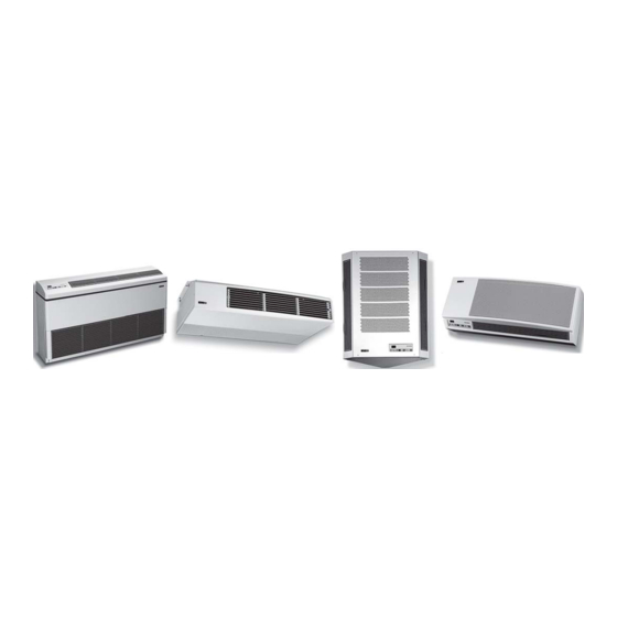
The EMI Air Handler Family ..................................... 2
Installer Supplied Items ........................................... 3
Materials of Construction ........................................ 3
Inspection ............................................................... 3
Items for Consideration ............................................ 3
Controls and Components ....................................... 3
Unit Mount Infrared Control Operation ...................... 3
Optional Controls/Components ................................ 3
Electrical Wiring ...................................................... 4
The Ductless Split System of Choice
CEILING MOUNTED AIR
HANDLER (CCP/CHP)
TABLE OF CONTENTS
EMI DUCTLESS SPLIT SYSTEM
T M
FCP/FHP, WCP/WHP, CNR, and CCP/CHP
CORNER MOUNTED AIR
HANDLER (CNR)
To obtain technical service or warranty assis-
tance during or after the installation of this unit, call
toll free:
1 - 800 - 228 - 9364
When calling for assistance, please have the
following information ready:
• Model number _____________________
• Serial number _____________________
• Date of installation _________________
RECOGNIZE THIS SYMBOL AS AN INDICATION
!
OF IMPORTANT SAFETY INFORMATION.
Final Installation Checks and Start-up .................. 4-5
Cooling Only Operation and Heat Operation ......... 6-7
Remote Thermostat Operation ............................. 8-9
Floor Model Air Handler (FCP/FHP) .................. 10-14
Ceiling Mounted Air Handler (CCP/CHP) .......... 15-16
Corner Mounted Air Handler (CNR) ................... 17-19
Wall Mounted Air Handler (WCP/WHP) ............ 20-22
Maintenance and Troubleshooting .................... 23-26
Test Unit Performance Data .................................. 27
Warranty ............................................................... 28
Specific Unit Installation
1
AIR HANDLERS
P/N# 240-4373, Rev. 1.2 [04/04]
WALL MOUNTED AIR
HANDLER (WCP/WHP)
www.enviromaster.com
!
Advertisement
Table of Contents

Related Manuals for EMI FCP/FHP


Summary of Contents for EMI FCP/FHP
-
Page 1: Table Of Contents
To obtain technical service or warranty assis- of the EMI ductless split system floor, wall, corner, or ceil- tance during or after the installation of this unit, call ing mounted air handler. Read these instructions thoroughly toll free: and carefully before attempting installation or operation. -
Page 2: Common To All Air Handlers
EMI Air Handler. factory for the appropriate literature. • Do not use the EMI Air Handler if it has dam- THE EMI DUCTLESS SPLIT SYSTEM AIR aged wiring, is not working properly, or has been HANDLER FAMILY CONSISTS OF damaged or dropped. -
Page 3: Installer Supplied Items
OPERATION Notify the Enviromaster International traffic depart- ment of all damages. EMI Air Handlers are equipped with a unit mount, infra- red compatible control package, optional on the CCP/CHP. This user friendly, microprocessor control is designed to ITEMS FOR CONSIDERATION... -
Page 4: Electrical Wiring
Use only HACR type break- ers. Select the proper wire for the ampacity rating. EMI indoor units do not contain a low volt trans- 3. Each unit must have a separate branch circuit pro- former. Low volt power is supplied by a trans- tected by a fuse or breaker. -
Page 5: Mode Switch
Dipswitches are factory set for a cooling only condenser. If Dry mode. If the dipswitches are set for cooling only (off – the indoor unit is matched with an EMI single zone or multi- off) then Heat and Dry will not be accessible (Figure 5). -
Page 6: Cooling Only Operation And Heat Operation
The fan will initial startup or if power is lost, there is a three-minute de- operate as described in “Fan Operation” (Figure 5). lay between compressor re-starts.) Made in Rome, New York, USA E-mail: emi@enviromaster.com... -
Page 7: Dry Mode Operation
EMI may factory install or supply a detailed field instal- lation kit to follow when pump is purchased as an option from EMI. (If purchased as an add-on in the field , please install per manufacturers instructions included with the pump. -
Page 8: Remote Thermostat Operation
OPERATION OPTION When selecting a thermostat other than those offered (Standard on CCP/CHP) by EMI, it is important to choose a 24V thermostat that matches your application. EMI equipment is compatible with INFRARED REMOTE CONTROL OPTION most mercury bulb, digital or power stealing thermostats. -
Page 9: Cooling Operation
COMMON TO ALL AIR HANDLERS Continued Units with an optional hydronic heat coil or chilled wa- COOLING OPERATION ter coil are also equipped with a freeze protection thermo- The electronic circuit board of the indoor unit also has stat. The freeze protection thermostat is designed to pro- an anti-short cycle timer (ASCT) feature designed to pro- tect the hydronic coil or chilled water coil from freeze up tect the compressor from short cycling. - Page 10 It is compatible with any the bottom left rear (room side) of the unit, as well EMI outdoor unit. The FCP is matched with a remote chilled through knockouts in the back of the unit.
-
Page 11: Floor Model Air Handler (Fcp/Fhp)
(See Figure 1 – Wall Box Positioning). EMI • All ducts, collars, and dampers are field supplied. The recommends that all electrical, refrigerant, and condensate back side has a 4"... -
Page 12: Chilled Water Piping
1000/1200 1500 36,42,48 ¾" I.D. " I.D. FCP/FHP Sound Levels Model# 9, 12 48.6 FCP/FHP Pow er Assiste d Outside Air Model# Total CFM Outside Air CFM 9, 12, 15 57.2 18, 24, 30 24, 30 60.6 36, 42, 48... - Page 13 (FCP/FHP) DIMENSIONS AND SPECIFICATIONS Continued NOTE: Due to EMI’s ongoing development programs, designs and specifications may change without notice. FCP/FHP Fresh Air Specifications* Model# Total CFM Outside Air CFM 9, 12, 15 18, 24, 30 36, 42, 48 1200 * Open or Motorized Damper FCP/FHP Electrical Specifications 26”...
- Page 14 (FCP/FHP) DIMENSIONS AND SPECIFICATIONS Continued Connection K.O.s for Open Fresh Air FHP 09- 30 FHP 09- 30 Motorized Damper and Power Assisted Fresh Air (2 Fan Type) Wall Box Dimensions: 14” (from finished floor level) x 17” wide x 8” deep Lagging holes positioned 8”...
-
Page 15: Ceiling Mounted Air Handler (Ccp/Chp)
NOTE: Front panel shipped separately in cartoning. DESCRIPTION 2. Secure the unit to the ceiling using appropriate hard- The EMI CCP/CHP is a highly effective ceiling mounted ware (screws for wood, anchors for masonry). evaporator for applications where fully exposed or partially 3. - Page 16 F wet bulb entering air temperature. 36, 42, 48 procedure.) 64,100 NOTE: Please refer to the Common section in the front of this manual for detailed instructions on: Controls/Components, Electrical Wiring, Start-Up, and more. Made in Rome, New York, USA E-mail: emi@enviromaster.com...
- Page 17 ITEMS FOR CONSIDERATION to secure the positioning bracket in place on the wall ac- • EMI’s CNR evaporator requires 24V power for con- cording to the proper hole location indicated on the tem- trol operation. When matching the CNR with a non- plates.
-
Page 18: Corner Mounted Air Handler (Cnr)
NOTE: Please refer to the Common section in the front of this manual for detailed instructions on: 2. Low voltage wiring (EMI requires 18 awg low voltage Controls/Components, Electrical Wiring, Start-Up, interconnect wiring) must be run to the outdoor unit. - Page 19 (CNR) DIMENSIONS AND SPECIFICATIONS NOTE: Due to ongoing development programs, design and specifications may change without notice. TRIM KIT (OPTIONAL) 18” POSITIONING 16 1/2” TOP PANEL BRACKET 13 5/8” 14 5/8” TUBING & ELECTRICAL ACCESS 31” MOUNTING HARDWARE MOTOR ACCESS DISCHARGE PANEL SECTION...
-
Page 20: Wall Mounted Air Handler (Wcp/Whp)
100’ including, a maxi- mum 35’ lift. PRODUCT DESCRIPTION • EMI’s WHP evaporator requires 24V power for con- trol operation. When matching the WHP with a non- The WHP is a ductless type evaporator, while the WCP... - Page 21 (WCP/WHP) DIMENSIONS AND SPECIFICATIONS NOTE: Due to ongoing development programs, design and specifications may change without notice. Slot for Bracket Wall Mount Bracket Permanent Washable Electrostatic Filter Condensate Pump Locations (Optional, Consult Factory for Pump Used) 2" Rear View Front Panel HEAT HIGH COOL...
- Page 22 15, 18 (230V High Speed Fan) 17,724 14,379 Model 23,073 16,763 9/12 20,563 17,564 15/18 29,031 21,178 24/30 32,320 22,539 17.7 24, 30 23,600 18,887 34,400 23,423 38,790 25,351 17.9 WHP’s ONLY Made in Rome, New York, USA E-mail: emi@enviromaster.com...
-
Page 23: Maintenance And Troubleshooting
MAINTENANCE AND TROUBLESHOOTING PROCEDURE for EMI Air Handlers with Unit Mount Infrared Controls POWER SUPPLY CHECK MAINTENANCE Service should be performed by a qualified service When trouble shooting any EMI product, it is important to first check the rating plate for proper field voltage and agency and an annual system check is recommended. - Page 24 The 24V-power supply can be measured by placing a meter across the red (R) and EMI Heat Pump systems utilize a reversing valve is brown (C) wires. The air handler will switch on and off the that is energized in the cooling mode.
-
Page 25: Error Codes
TROUBLESHOOTING PROCEDURE Continued HEATING ERROR CODES This unit is designed to utilize two stage heating. The Should for some reason one of the two temperature sen- first stage being the compressor and the second is electric sors become disconnected or fail, an error code will appear heat. -
Page 26: Frequently Asked Questions
A: While the unit is in cooling or heating and auto fan mode is selected, Fan speed will be determined by Q: The system has just been installed using an EMI the microprocessor and speed adjustment will be indoor unit and a non-EMI condenser. There is no made according to room and setpoint temperatures. -
Page 27: Test Unit Performance Data
TROUBLESHOOTING PROCEDURE Continued and have this information ready when calling. Make sure to The Test Unit Performance Data sheet below is provided include the Model Number, Serial Number, Date of Installa- for use by a qualified service professional in the event that tion. -
Page 28: Warranty
WHAT WE WILL COVER EMI will replace any defective part returned to EMI's approved service organization with a new or rebuilt part at no charge. The replacement part assumes that unused portion of this warranty.
Need help?
Do you have a question about the FCP/FHP and is the answer not in the manual?
Questions and answers