Table of Contents
Advertisement
Advertisement
Table of Contents

Subscribe to Our Youtube Channel
Related Manuals for 2easy DT 2-wire


Summary of Contents for 2easy DT 2-wire
- Page 1 DT 2-wire Video Intercom System Technical Guide...
-
Page 2: Table Of Contents
CONTENT Section1 - Introduction System Features- - - - - - - - - - - - - - - - - - - - - - - - - - - - - - - - - - - - - - - - - - - - - - - - - - - - - - - - - 1 System Capacity- - - - - - - - - - - - - - - - - - - - - - - - - - - - - - - - - - - - - - - - - - - - - - - - - - - - - - - - - 1 System Extension- - - - - - - - - - - - - - - - - - - - - - - - - - - -... - Page 3 Section3 - Cables and Connections General Rules for Installation-- - - - - - - - - - - - - - - - - - - - - Connecting the Connectors - - - - - - - - - - - - - - - - - - - - - - - - - - - - - - - - - - - - - - - - - - - - - - - - -28 Installation Height - - - - - - - - - - - - - - - - - - - - - - - - - - - - - - - - - - - - - - - - - - - - - - - - - - - - - - - -28...
-
Page 4: Section1 - Introduction
Section1 - Introduction System Features • With only 2 wires (no polarity) throughout the whole installation, the 2-wire DT system is a simplified installation system with minimum wiring and powerful features. The minimum wiring drastically reduces installation times and errors. By means of FM video modulation and ASK data transmission technology, system provides better protection against interference, which guarantees best color quality at all points of the installation. -
Page 5: Apartment Applications
Villa Application Although the DT system is mainly designed for the small apartment system usage, it can be used in villa or villa group applications. Multi Monitors can be installed in a family with the same User Code, or many houses can be connected as one system, and all of these Monitors can have calling conversation each other. -
Page 7: Section2 - Units And Installations
Section2 - Units and Installations Door Station Bit-4=off 1 2 3 DMR11/ID/D8 DMR11/D8 EP11/D24 Bit-4=on 1 2 3 DMR11/S4 DMR11/ID/S4 EP11/S12 Features • Full anodize aluminum panel. • SONY color CCD camera. • camera angle adjustable. • ID card access control •... -
Page 8: Parts And Functions
Parts and functions Camera Lens CDS Sensor Infrared LED Camera Angle adjustment Speaker Speaker Microphone adjustment Name plate Connection Board Call button 18 mm 45 mm 114.5 mm 123 mm Place Name Plate Press down and shift right/left to open the transparent name plate cover, then insert the name paper, then put the plate cover back to the panel. -
Page 9: Standard Installation
Standard Installation Camera Angle adjustment Open the mounting box of the panel, use a cross screw to adjust the view angle of the camera before installation. Installation with expanding panel Jointer*2 Stopper Note +12V T/R - LK - (G ND)L K+( COM) T/R+ N. -
Page 10: Terminal Descriptions
Terminal Descriptions T/R -T/R+ +12V LK - (GND) LK+(COM) N.O. EB - DMR11 Connection Board L1 L2 • 12VDC power output. +12V: • power ground. LK-(GND): • electronically load activation relay contact common. LK+(COM): • electronic load activation relay normally open contact (the default setting for this terminal is NO, this NO.: terminal can be configured to NC, normally-closed contact by the DT CONFIG software). -
Page 11: Dip Switches Settings
DIP Switches settings Total 6 bits in the DIP switches can be configured. The switches can be modified either before or after installation. • Bit-1 and Bit 2 is for Door Station ID settings, when muti Door Stations are installed in the system, these two bit ON(1) OFF(0) must be set correctly, the first Door Station set to 00, the second one set to 01, the third one set to 10, the fourth one... -
Page 12: Door Station Lock Connections
Door Station Lock Connections +12V T/R - T/R+ LK - (GND) LK+(COM) N.O. EB - DMR11 Connection Board +12VLK - (GND) T/ R - T/ R + LK +( CO M)N. O.EB +E B - L1 L2 1. Direct lock connection Use the power of the system to supply for the electronic lock, so that the lock can connect to the Door Station directly, without an additional power supply for the electronic lock. - Page 13 B. Connection for Power-- off-to-Unlock type: DIPS +12V LK - (GND) LK+(COM) N.O. 1 2 3 4 12V 300mA DIPS-5: set to on, EB - unlocking time is 5 seconds. Jumper set to 2-3 position set to Normally Closed on the Unlock Relay mode on DT software.
-
Page 14: Proximity Id Card Operation
Proximity ID Card Operation • Up to 1000 user cards can be registered by the Door Station. • Easy management with LED state and Sound hint. • There are two master cards, one MASTER CARD ADD card and card, When adding a new master MASTER CARD DELETE card, the old one will be replaced automatically. - Page 15 Add user cards by Room: Press a certain button on the Show the MASTER Show the Door Station, then show the MASTER CARD CARD ADD card again to card in standby cards which to be assigned to confirm and exit. this Room.
-
Page 16: Monitor
Monitor Features screen Touch Screen Indicator Microphone Speaker CALL CALL button POWER + Button IN-USE UNLOCK UNLOCK button - Button TALK/MON TALK/MON button IN-USE LED indicator MENU Button INTERCOM INTERCOM Button UNLOCK UNLOCK Button TA LK/ M O NI TOR TALK/MON Button Microphone... -
Page 17: Terminal Descriptions
Terminal Descriptions • Door bell call button. SW+: Monitor • Door bell call button. SW-: Connection Board • External ringer output(12Vdc 100mA) EXT-RING: • Ground. GND: 1 2 3 4 5 6 • Video signal output. EXT-RING VIDEO: VIDEO • DIP switches for system configurations. - Page 18 Step 1: Run the DT CONFIG software. Connect the USB-485 Convertor to the DMR11 Door Station and the PC, double click the software to make it running on the PC, then click the Namelist tap, the screen will be showed: Step 2: Edit the namelist.
-
Page 19: Camera Auto Switching
Camera Auto Switching When multi Door Stations or CCTV cameras are installed in the system, Monitor can display the video one after another. The Monitoring time for each Station or Camera must be set by the DT-CONFIG software manually to enable the Auto Switching function(DT-CONFIG-- >Parameter-- >Camera Switching Time). -
Page 20: User Code Setup
User Code Setup In the DT system, every apartment must have a unique identification called User Code. The DIP switches are used to configure the User Code for each Monitor. • Bit-1 to Bit-5 are used to User Code setting. The value is from 1 to 32, which have 32 different codes for 32 apartments. -
Page 21: Monitor Extending Connection
Monitor Extending Connection CA LLU N LO C K TALK/M ON IN-USE 1 2 3 4 5 6 1 2 3 4 5 6 SW-EXT-RING GNDVIDEO 1. Door Bell Call Button Additional door bell call button can be connected to the Monitor, so that the visitors can ring the door bell again in front of the user's apartment. -
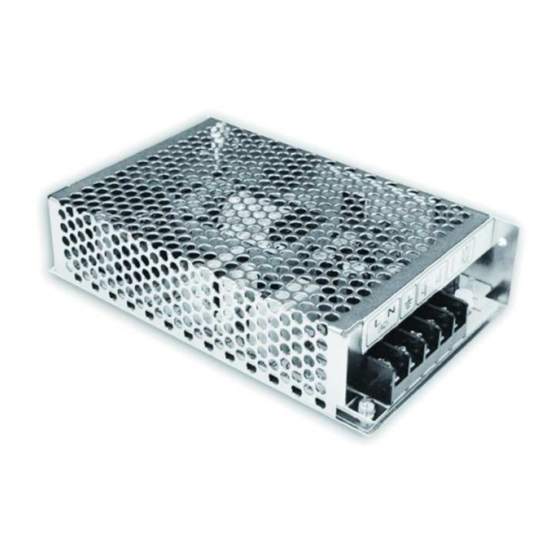
Page 22: Accessories
Accessories PS5 - Power Supply The PS5 power supply unit is designed for DT system to supply up to 32 Monitors and total 4 Door Stations at the same time. • Universal AC input/full range. • Multi protection: short circuit, overload, over voltage •... - Page 23 DIN Installation DIN nail 85~260AC DT - System - Technical Guide...
-
Page 24: Dps
This unit is a power supply adaptor for the PS5 or PS4 power supply, it transfers the power from the power DPS: supply to the suitable power for the non-polarity bus. Note that the DPS must work together with the PS5 or PS4 power supply. - Page 25 DPS/DBC Dimensions Direct Wall Mounting DIN Rail Mounting Use the screws to fasten the unit on the wall directly. Install on the DIN Rail. 85mm DT - System - Technical Guide...
-
Page 26: Dbc-4 Unit
DBC-4 Unit Distributor is a 4 output user distributor for DT system, to approach the star topology connection in the DBC-4 apartment system. See Section 3 Cables and Connection for detail connection information. set to 120 for the last DBC-4 DBC-4 on the building, the others Video Match... - Page 27 DBC-4/DPS-4 Dimensions 140mm 70mm upward 84mm 32mm Trunk Bus A/B/C/D port: Connect to Monitors/Door Station Trunk Bus: Bus input/output. Direct Wall Mounting DIN Rail Mounting DT - System - Technical Guide...
-
Page 28: Dcu Unit
DCU Unit The DCU unit is a Multi function device which can connect 2 CCVT cameras and light/lock control. • DIP1 Contact relay Common terminal COM: DIP2 • Contact relay Common terminal • Contact activate button EB+, EB-: ON1 2 3 4 5 6 ON1 2 3 4 •... - Page 29 Dimensions Direct Wall Mounting DIN Rail Mounting 80mm DT - System - Technical Guide...
-
Page 31: Section3 - Cables And Connections
Section3 - Cables and Connections General Rules for Installation Connecting the Connectors Before screw the wire to the plug-in connector, it's important to process the wire in the correct way. See the following steps to connect the wire. 1. Strip the wire 2. -
Page 32: Table Of Cables And Distance
Table of Cables and Distance The maximum distance of the wiring is limited in the DT system. Using different cables may also affect the maximum distance the system can reach. The farthest monitor When Monitor quantity < 20 Cable Usage Twisted cable 2x0.75 mm Twisted cable 2x1 mm When Monitor quantity >... -
Page 33: System Wirings And Connections
System Wirings and Connections 1. Basic IN-OUT wiring mode 1 2 3 4 5 6 Code=32, DIP-6=on 1 2 3 4 5 6 Code=31, DIP-6=off 1 2 3 4 5 6 Code=1, DIP-6=off 85~260AC ID=00 3 4 5 6 DT - System - Technical Guide... -
Page 34: Basic In-Out Wiring Mode (1~N Risers)
2. Basic IN-OUT wiring mode (1~n risers) 1 2 3 4 5 6 1 2 3 4 5 6 Code=8, DIP-6=on Code=4, DIP-6=on 1 2 3 4 5 6 1 2 3 4 5 6 Code=3, DIP-6=off Code=7, DIP-6=off 1 2 3 4 5 6 1 2 3 4 5 6 Code=5, DIP-6=off Code=1, DIP-6=off... -
Page 35: In-Out Wiring With One-User Distributor
3. IN-OUT wiring with One-user distributor 1 2 3 4 5 6 1 2 3 4 5 6 Code=32, DIP-6=on Code=31, DIP-6=off 1 2 3 4 5 6 1 2 3 4 5 6 Code=30, DIP-6=on Code=29, DIP-6=off 1 2 3 4 5 6 1 2 3 4 5 6 Code=9, DIP-6=on Code=8, DIP-6=off... -
Page 36: Basic Star Wiring Mode
4. Basic Star wiring mode 1 2 3 4 5 6 1 2 3 4 5 6 Code=32, DIP-6=on Code=31, DIP-6=on 1 2 3 4 5 6 1 2 3 4 5 6 Code=29, DIP-6=on Code=30, DIP-6=on 1 2 3 4 5 6 1 2 3 4 5 6 Code=3, DIP-6=on Code=4, DIP-6=on... -
Page 37: 5. 4 Door Stations And Star Wiring Mode
5. 4 Door Stations and star wiring mode 1 2 3 4 5 6 1 2 3 4 5 6 Code=4, DIP-6=on Code=3, DIP-6=on 1 2 3 4 5 6 1 2 3 4 5 6 Code=2, DIP-6=on Code=1, DIP-6=on DPS-4 A B C D 85~260VAC... -
Page 38: 6. 1 Door Station And 2 Cctv Cameras
6. 1 Door Station and 2 CCTV cameras 1 2 3 4 5 6 1 2 3 4 5 6 Code=4, DIP-6=on Code=3, DIP-6=on 1 2 3 4 5 6 1 2 3 4 5 6 Code=2, DIP-6=on Code=1, DIP-6=on 85~260VAC ID=00 3 4 5 6... -
Page 39: Mixed 1/4 User Distributors Wiring
7. Mixed 1/4 user distributors wiring 1 2 3 4 5 6 Code=32, DIP-6=on 1 2 3 4 5 6 1 2 3 4 5 6 Code=31, DIP-6=on Code=30, DIP-6=off 1 2 3 4 5 6 1 2 3 4 5 6 Code=4, DIP-6=on Code=3, DIP-6=on 1 2 3 4 5 6... -
Page 40: Section4 - Setup And Debug
Busy State Management Calls and busy state are managed according to the programmed system times • Pick-up waiting time: this is the duration from when a call is made from a Door Station to when the called Monitor is picked up; the system will cut off the call after this period of time.(the default setting is 30 seconds) •... -
Page 41: Door Station Function
Door Station Function 1. Call Forwarding: Every call button on the Door Station has a button ID,which is associated with a Monitor ID(Monitor address or code). When a call button is pressed on a Door Station: • Door Station free: the Door Station will output the call forwarding tone (a long beep(Di~) in every 3 seconds) and the nameplate light will blink. -
Page 42: System Setup
System Setup What’s User Code In 2-wire DT system, each Monitor installed in system must be programmed with a calling address or calling number, which is User Code. For Monitor, User Code is defined by 1~5 bits DIP switchers on the connection board, according the User Code rules. For example, if you want to program the Monitor’s User Code to be “03”, the Monitor’s 1~5 bit DIP switchers should be set as: ON, ON, OFF, OFF, OFF(please refer to User Code table at section2-Monitor). -
Page 43: What's Slave Address
What's Slave Address 2-wire DT system is capable of connecting up to 4 Monitors in one apartment, which means they will have the same User Code, and will be called simultaneously. In this condition, the Monitors should be programmed as below: •... -
Page 44: Online Search
Online search Online search function is designed for the purpose of getting a quick view of the Monitors installing situations, or to check if each of them works or not. This is very useful for installation maintain. There are 3 different ways to use the Online Search function, manually search, use the ID tab and use the DT CONFIG software. -
Page 45: Simulating Call
2. Use ID tag The Door Station will be equipped with an Online search Card with a card number of 16666666, which is designed for the online search only. 16666666 Show the Online search card on the card window one time within 3 seconds, the Door Station will start to search the Right column Monitors;... -
Page 46: Section5 - Dt Config Software
Section5 - DT CONFIG Software Introduction DT-CONFIG software is a powerful configuration and debug tool to setup the 2-wire system. As simplified software tools, DT-CONFIG allows installers to check and program Door Stations rapidly, which is especially useful in complex installation. -
Page 47: Interface Preview
Interface Preview 1. Main Menu (Information Menu) Information tab shows the product Model, Hardware Version, Software Version, Serial No. Access Control, Access Card Number information. On the tab, Installer's Information user can input the Project Name Block Name for this Door Station. Note: is a unique number Series No. - Page 48 3. Name list Setup This menu is for the name list input and download operations. All user namelist can be input and download to the Door Station and the Door Station will send the namelist to every Monitor in the system.
- Page 49 5. Debug Tool The debug tool is very useful when trouble shoot or maintain the system: • User Code Range: To change the User Code start and end address, only set valid range will save more time. • Button: Use this Online Check button to start Online searching, and the result will be showed in list...
- Page 50 DT User Code Programming Table page1/2 User code Bit state Room Name Label Remark 1 2 3 4 5 1 2 3 4 5 1 2 3 4 5 1 2 3 4 5 1 2 3 4 5 1 2 3 4 5 1 2 3 4 5 1 2 3 4 5 1 2 3 4 5...
- Page 51 DT User Code Programming Table page1/2 User code Bit state Room Name Label Remark 1 2 3 4 5 1 2 3 4 5 1 2 3 4 5 1 2 3 4 5 1 2 3 4 5 1 2 3 4 5 1 2 3 4 5 1 2 3 4 5 1 2 3 4 5...
- Page 52 GuangZhou Video-Tech Electronics Co.,Ltd www.v-tec.com.cn www.viewtech2wire.com DT System Technical Guide_V1.0...
Need help?
Do you have a question about the DT 2-wire and is the answer not in the manual?
Questions and answers