NOCO Genius Genius G3500 User Manual
Noco genius charger
Hide thumbs
Also See for Genius G3500:
- User manual ,
- Owner's manual & user manual (47 pages) ,
- Product information manual (31 pages)
Table of Contents
Advertisement
G3500
User Guide
DANGER
PRIOR TO USE, READ AND UNDERSTAND
PRODUCT SAFETY INFORMATION.
Failure to follow the instructions may result
in ELECTRICAL SHOCK, EXPLOSION,
or FIRE, which may result in SERIOUS
INJURY, DEATH, DAMAGE TO DEVICE or
PROPERTY. Do not discard this information.
Welcome.
Thank you for buying the NOCO Genius
G3500. Read and understand the User Guide before
operating the charger. For questions regarding our
chargers, view our comprehensive support information at
www.no.co/support. To contact NOCO for personalized
support (not available in all areas), visit www.no.co/connect.
What's In The Box.
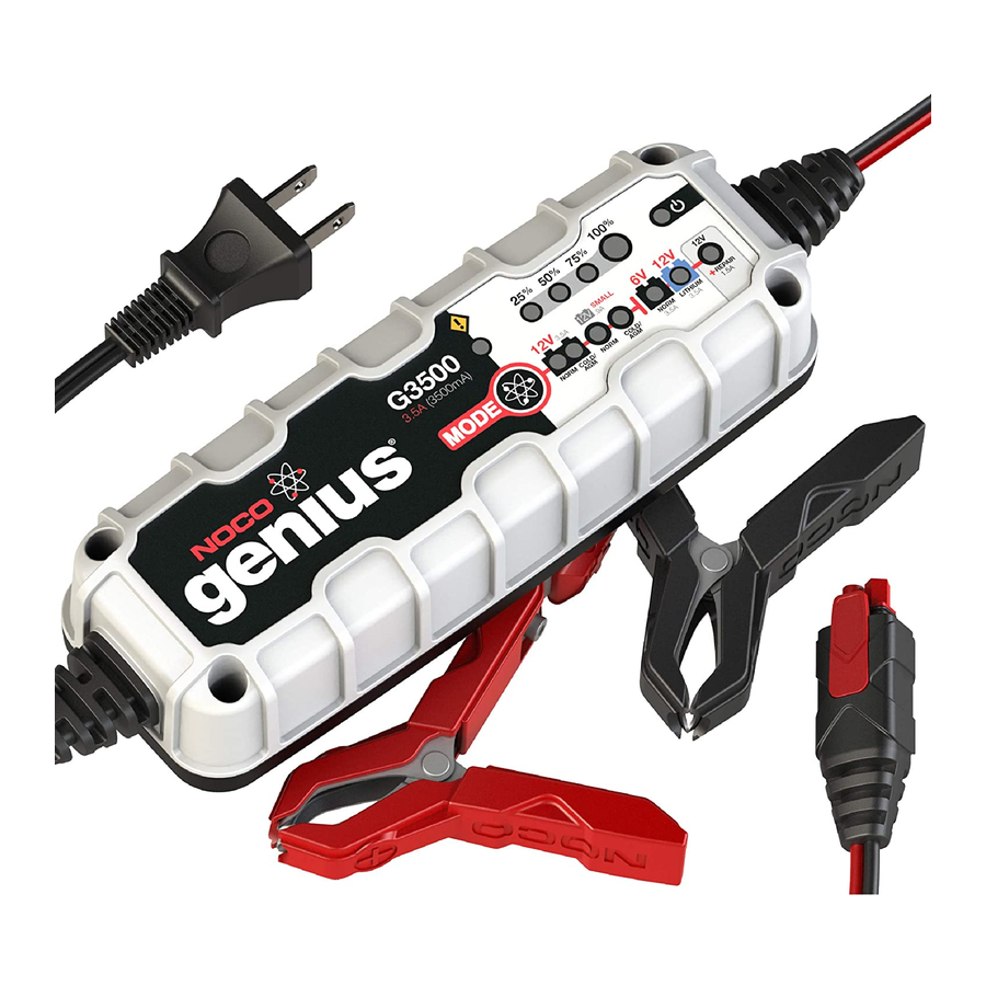
• G3500 Smart Charger
• (1) Battery Clamp Connectors
• (1) Eyelet Terminal Connectors
• User Guide
• Information Guide and Warranty
V2.0
®
Advertisement
Table of Contents

Related Manuals for NOCO Genius Genius G3500


Summary of Contents for NOCO Genius Genius G3500
-
Page 1: User Guide
INJURY, DEATH, DAMAGE TO DEVICE or PROPERTY. Do not discard this information. Welcome. ® Thank you for buying the NOCO Genius G3500. Read and understand the User Guide before operating the charger. For questions regarding our chargers, view our comprehensive support information at www.no.co/support. - Page 2 Glenwillow, OH 44139 United States of America About G3500. ® The NOCO Genius G3500 represents some of the most innovative and advanced technology on the market, making each charge simple and easy. It is quite possibly the safest and most efficient charger you will ever use.
- Page 3 indicated on the charger by a red line. It is important to understand the differences and purpose of each charge mode. Do not operate the charger until you confirm the appropriate charge mode for your battery. Below is a brief description: Mode Explanation In Standby mode, the charger is not...
- Page 4 Mode Explanation For charging 6-volt Wet Cell, Gel Cell, Enhanced Flooded, Maintenance-Free and Calcium batteries. When selected, a NORM white LED will illuminate. 7.25V | 3.5A | 2-120Ah Batteries Press & Hold For charging 12-volt lithium-ion batteries, including lithium iron phosphate. When selected, a blue LED will illuminate.
- Page 5 BATTERIES MAY BE UNSTABLE AND UNSUITABLE FOR CHARGING. Using 12V Repair. [Press & Hold] 12V Repair is an advanced battery recovery mode for repairing and storing, old, idle, damaged, stratified or sulfated batteries. Not all batteries can be recovered. Batteries tend to become damaged if kept at a low charge and/or never given the opportunity to receive a full charge.
- Page 6 1.) Connect the positive (red) battery clamp or eyelet terminal connector to the positive (POS,P,+) battery terminal. 2.) Connect the negative (black) battery clamp or eyelet terminal connector to the negative (NEG,N,-) battery terminal or vehicle chassis. 3.) Connect the battery charger’s AC power plug into a suitable electrical outlet.
- Page 7 Understanding Charge LEDs. The charger has four (4) Charge LEDs - 25%, 50%, 75% and 100%. These Charge LEDs indicate the connected battery(s) state-of-charge (SOC). See the explanation below: Explanation The 25% Charge LED will slowly Red LED pulse “on” and “off”, when the battery is less than 25% fully charged.
- Page 8 Understanding Advanced Diagnostics. Advanced Diagnostics is used when displaying Error Conditions. It will display a series of blink sequences that help you identify the cause of the error and potential solutions. All Error Conditions are displayed with the Error LED and Standby LED flashing back and forth.
- Page 9 Memory Returns to last selected mode when restarted Interactive Alters the charging process based on organic battery feedback Recovery Applies a high-voltage pulse charge when low-voltage, sulfation or lost capacity is detected Safe Protects against reverse polarity, sparks, overcharging, overcurrent, open-circuits, short-circuits and overheating Fast Charges two times faster than traditional...
- Page 10 Optimization Stabilizes internal battery chemistry for increased performance and longevity Maintenance Plus Keeps the battery fully charged without overcharging allowing the charger to be safely connected indefinitely Energy Save Minimizes energy consumption when full power is not needed Load Tracking Charge LEDs dynamically track the batteries state-of-charge when a load outpaces the charge current...
- Page 11 Charging Steps. Voltage (V) Step Current (A) Step 1 & 2: Analyze & Diagnose Checks the battery’s initial condition, including voltage, state-of-charge and health, to determine if the battery is stable before charging. Step 3: Recovery Initializes the Recovery desulfation process (if needed) for deeply discharged or sulfated batteries by pulsing small amounts of current.
- Page 12 Step 8: Maintenance Continuously monitors the battery to determine when a maintenance charge should be initiated. If the battery voltage falls below its target threshold, the charger will restart the Maintenance cycle until voltage reaches its optimal state and then discontinues the charge cycle. The cycle between Optimization and Maintenance is repeated indefinitely to keep the battery at full charge.
- Page 13 Technical Specifications. Input Voltage AC: 110-120 VAC, 50-60Hz Working Voltage AC: 85-130 VAC, 50-60Hz Efficiency: 85% Approx. Power: 60W Max Charging Voltage: Various Charging Current: 3.5A (12V & 6V), .9A (12V Small) Low-Voltage Detection: 2V (12V), 2V (6V) Back Current Drain: <5mA Ambient Temperature: 0°C to +40°C...
Need help?
Do you have a question about the Genius G3500 and is the answer not in the manual?
Questions and answers