Table of Contents
Advertisement
Quick Links
Download this manual
See also:
Configuration Manual
Advertisement
Table of Contents

Related Manuals for Eldes EPIR2


Summary of Contents for Eldes EPIR2
- Page 1 EPIR2 GSM Alarm System...
-
Page 2: Safety Instructions
• DO NOT attempt to repair the system yourself - any repairs must be carried out by fully quali- fied personnel only The EPIR2 comes with its own power supply unit so you can plug it in straight away. The unit is not meant for outdoor use, i.e. you should use it inside a building and the power supply must be plugged into a standard Euro 2-pin socket or UK 3-pin socket (depending on the version you have bought). -
Page 3: Table Of Contents
Copyright © “ELDES UAB”, 2014. All rights reserved. It is forbidden to copy and distribute information in this document without advance written authorisation from ELDES UAB. We reserve the right to update or modify this document and/or related products without warning. The EPIR2 GSM Alarm Sys- tem complies with the essential requirements and relevant provisions of Directive 1999/5/EC. - Page 4 ELDES UAB will not take any responsibility for the loss of personal effects, property or revenue whilst using the system. The liability of ELDES UAB is limited to the value of the system purchased. ELDES UAB is not affiliated with any mobile/wireless/cellular provider and is therefore not respon- sible for the quality of such services.
-
Page 5: Technical Specifications
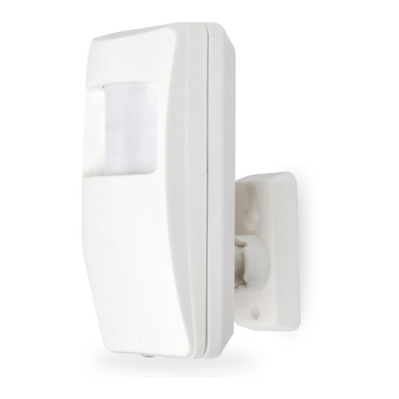
Protecting your home and property with the EPIR2 alarm system Where and how to use the alarm system The EPIR2 is a convenient, easy to use, remote control security system for houses, cottages, coun- try homes, garages and other buildings. - Page 6 BELL- / COM BELL+ BATTERY BACK SIDE INSIDE VIEW EPIR2 holder for fixing on the wall 2. Lens for movement detector and LED 3. Power supply socket to connect to mains electricity 4. Power supply transformer Power supply connection lead 6.
-
Page 7: Quick Start Guide
1. QUICK START GUIDE OVERVIEW This section tells you how to install the EPIR2 system quickly and easily and covers all the pro- cedures required for full system operation. The alarm system functions via the GSM network, so you will first need to purchase a SIM card so you can ‘talk’ to and program your device via your mobile phone. -
Page 8: Prepare The Sim Card
This will help ensure that when you install the SIM card in the EPIR2 it will operate correctly. IMPORTANT RECOMMENDATIONS • We advise you to choose the same GSM SIM provider for your system as for your mobile phone. -
Page 9: Plug The Power Supply Connector Into The Device
Slide the SIM card cover back Fit the front cover and replace to lock SIM card in place. screw. For more information see the diagram of the EPIR2 and the description of components on page <6>. 1.4. Plug the power 1.5. Place the device into 1.6. -
Page 10: About The Back-Up Battery And How To Replace It
During mains failure the battery should power the system for up to twenty-four hours. How to replace the battery: 1. Unplug the power supply 2. Remove the EPIR2 from its 3. Unplug the power supply from the mains electricity holder. -
Page 11: How To Program Epir2 System
SMS/text message management. NOTE If you wish to program the EPIR2 system by SMS/text message, please refer to section 3. HOW TO PROGRAM THE SYSTEM USING YOUR MOBILE PHONE. If not, please proceed to section 1.9.1 Download ELDES Configuration Tool software... - Page 12 Specify a location for setup file and left-click on the Save button. We recommend placing the file on your desktop. 1.9.2. install ELDES Configuration Tool software. Double left-click on the downloaded setup file to run it. EPIR2 User Manual v.1.4...
- Page 13 In the newly popped-up window left-click on the Next button to continue. In the next window left-click on the Next button to continue. EPIR2 User Manual v.1.4...
- Page 14 In the following window left-click on the Next button to continue. In the next window left-click on the Next button to continue. EPIR2 User Manual v.1.4...
- Page 15 In the following window left-click on the Install button to begin the installation process. Wait for the installation progress to complete and do not click on any button. EPIR2 User Manual v.1.4...
- Page 16 You do not have to repeat the installation process the next time when you want to run ELDES Configuration Tool software again. 1.9.3. Connect EPIR2 to your PC via the USB cable IMPORTANT: Before connecting EPIR2 to your PC via the USB cable, first ensure the EPIR2 is powered up. Plug the miniUSB...
- Page 17 1.9.4. Run ELDES Configuration Tool software. Run the software anytime you want by double left-clicking on the ELDES ConfigTool shortcut located on the desktop. Once the software is up and running, left-click on the USB connection / -connect- button. Type in 4-digit...
-
Page 18: How To Arm And Disarm The System
Before arming the system it is necessary to close all doors and windows in the secured area and move yourself away from the movement detection field. Alternatively, you can arm/disarm your EPIR2 system by sending an SMS text message (see 3. HOW TO PROGRAM THE SYSTEM USING YOUR MOBILE PHONE). -
Page 19: A 15 Second Delay Allows You To Leave The Premises
You can also program the system to send an SMS/text message to all users (see ELDES Configu- ration Tool software’s Help section). -
Page 20: Receiving An Sms/Text Message When Temperature Exceeds The Set Values
OVERVIEW Your EPIR2 has a built-in wireless module. This section tells you how to bind and remove a wireless device using your PC and ELDES Configuration Tool as well as briefly describing every available wireless device which can operate together with your EPIR2 system. -
Page 21: How To Bind A Wireless Device To The System
You can also attach more devices which are not part of the ELDES wireless range by using expan- sion module EW1 with 2 inputs and 2 programmable outputs Main features of built-in wireless module: • Up to 16 ELDES wireless devices per one EPIR2 unit;... - Page 22 3. Open Wireless Device Management section. This section uses a radar diagram to show ELDES wireless devices visible to EPIR2 within its wire- less range. Unbound devices are indicated by a device icon with a red stripe above the icon. Once the device...
- Page 23 Battery Level – Battery status of the wireless device: • 0% - Battery is empty; • 100% - Battery is full. Signal Level – Wireless connection signal strength: • 0% - No wireless signal; • 100% - Wireless signal is perfect. EPIR2 User Manual v.1.4...
-
Page 24: How To Remove A Wireless Device From The System
1. Turn on the wireless device by following the instructions provided in the user manual of the wireless device. 2. Run ELDES Configuration Tool software and left-click on the USB connection / -connect- button. 3. Open Wireless Devices section. 4. In the radar diagram, left-click (highlight) on the bound wireless device icon (green stripe above the icon) to select it. -
Page 25: Ekb3W Wireless Keypad Overview
In order to correctly remove the wireless device from the system, the user must remove the device using SMS text message or ELDES Configuration Tool software and restore the parameters of the wireless device to default afterwards. If only one of these actions is carried out, the wireless device and the system will attempt to exchange data to keep the wireless connection alive. -
Page 26: Keys Functionality
(by default – every 60 seconds) transmits the supervision signal, identi- fied as Test Time, to the EPIR2 system. When the keypad operates in the sleep mode, only the trans- mitter remains operational, while the receiver as well as the the LED indicators and the back-light are switched OFF. - Page 27 NOT wake up and will NOT initiate the Back-light Timeout as well as the buzzer will NOT emit short beeps and the LED indicators will NOT light ON. To configure Back-light Timeout and Test Time parameters, please refer to ELDES Configuration Tool software.
- Page 28 • Manual - The system becomes instantly Stay-armed after the user presses the [STAY] key and enters a valid user password on the EKB3W keypad. There is no exit delay countdown when activating Stay mode manually. EPIR2 User Manual v.1.4...
- Page 29 To activate a bypassed zone, enter the same combination again. NOTE: The alternative way to activate all bypassed zones at once is to disarm the system. NOTE: Zones can only be bypassed when the system is not armed. EPIR2 User Manual v.1.4...
- Page 30 (Z13-Z34). The number of the violated high-numbered zone or tamper can be calculated using the table below according to the formula: number from zone LED section B + number from zone LED section A. EPIR2 User Manual v.1.4...
-
Page 31: Ewk1 And Ewk2 Wireless Keyfob Overview
Zone LED 6 = 6 2.4. EWK1 and EWK2 wireless keyfob overview EWK1/EWK2 is a wireless keyfob intended for using with EPIR2 alarm system. EWK1/EWK2 keyfob features four configurable buttons intended to operate according to individual needs. After the button is pressed, EWK1/EWK2 internal buzzer’s sound signal (and red indicator; on EWK2 only) confirms a successfully carried out command. - Page 32 2. To disarm the system, press 1 of 4 keyfob buttons set to disarm the system (by default, EWK1 ; EWK2 - Disarm Disarm system system 3. After the system is successfully disarmed, it will reply with confirmation by SMS message to User 1 phone number (by default). User EPIR2 EPIR2 User Manual v.1.4...
-
Page 33: How To Program The System Using Your Mobile Phone
This can be configured using ELDES Configuration Tool software. In order to configure and control the EPIR2 system using SMS/text message, send the text com- mand to the phone number of EPIR2 from one of the pre-programmed user numbers. - Page 34 Add or change XXXX_NRn: NRn = [NR1... NR10] 1111_ a single user +4417001111111 NR1:+4432101234 The EPIR2 alarm system phone number or XXXX_NRn: allows you to enter up to ten 004417001111111 different mobile numbers to gain access to and control or XXXX_ the system.
- Page 35 A combination of different phone number formats is allowed to use. NOTE: The underscore symbol ‘_’ in these instructions represents a space. So when typing an SMS/text message, replace the underscore symbol with a single space. EPIR2 User Manual v.1.4...
- Page 36 • status of zones & PGM outputs (ON/OFF); • zone alarm texts; • PGM output names. NOTE: The underscore symbol ‘_’ in these instructions represents a space. So when typing an SMS/text message, replace the underscore symbol with a single space. EPIR2 User Manual v.1.4...
- Page 37 59]; SS = seconds, [00... 59] OFF:HH.MM.SS The EPIR2 system supports wireless PGM outputs allowing connection and control of various electrical appliances: water pumps, heating, lighting, blinds etc. The maximum number of PGM wireless outputs which can be connected to the EPIR2 system is 32.
- Page 38 Enable SMS/text XXXX_SMS:ON 1111_SMS:ON message from the system in case of alarm NOTE: The underscore symbol ‘_’ in these instructions represents a space. So when typing an SMS/text message, replace the underscore symbol with a single space. EPIR2 User Manual v.1.4...
- Page 39 External Power Supply & Backup Battery Status Notification Settings Function Command Value Range / Comment Example Disable SMS/text XXXX_M:OFF The EPIR2 will let you know 1111_M:OFF message regard- when the mains 230V power ing the external supply fails or recovers. In some power supply...
- Page 40 System Control from Any Phone Number Settings Function Command Value Range / Comment Example Unblock unknown XXXX_STR:ON By default, the EPIR2 alarm sys- 1111_STR:ON incoming num- tem can only be accessed from bers each of up to ten mobile phones that you program into it..
- Page 41 SMS/text message. The system will make a phone call to you and enable the microphone in EPIR2. You must answer the call within 20 seconds to listen in to what is happening in your property. If you do not pick up, the system will stop trying and will return to its previous state.
- Page 42 (if any) of a specified wire- less device. NOTE: The underscore symbol ‘_’ in these instructions represents a space. So when typing an SMS/text message, replace the underscore symbol with a single space. EPIR2 User Manual v.1.4...
- Page 43 Choose your preferred language for the device before you change the pre-set password. Use the code shown in the table below to set your device to your preferred language. Then send the code via SMS/text message to the SIM card inserted in your EPIR2 alarm system. LANGUAGE...
-
Page 44: Troubleshooting
If you cannot find the answer to your problem above, please contact your local distributor. More up to date information about your device and other ELDES products can be found at www.eldes.lt EPIR2 User Manual v.1.4... -
Page 45: Additional Information For Advanced Users
Your EPIR2 system comes equipped with wired zone and output terminals, therefore you may wish to connect a wired sensor, wired siren or a LED indicator to your EPIR2. The wired output can be used for wired siren connection or for system condition indication, while the wired zone is intended for one wired sensor connection. - Page 46 BELL- / COM +8... +15V. The current consumption must not BELL exceed 150 mA. BELL+ 4. Screw in the terminals. 5. Insert back the terminal block. EPIR2 User Manual v.1.4...
- Page 47 6. Set the Output Mode as Siren under Management section in the ELDES Configuration Tool software. NOTE: No additional power supply is required for the siren/bell. NOTE: For a more convenient installation, we recommend using EWS1 and EWS2 wireless sirens.
-
Page 48: How To Connect A Sensor To The Wired Zone
NOT mandatory to use. Please, obtain these components from your local store if desired. 5.2. How to connect a sensor to the wired zone EPIR2 system comes equipped with the wired zone, therefore you may wish to connect a wired sensor to your system. - Page 49 COM (usually - green) wire to BELL - / COM terminal. 4. Connect the 5.6 kΩ nominal resistor, supplied with your EPIR2 system, across BELL- / COM and Z2 terminal in parallel to the connected wires of the detection device.
- Page 50 6. Insert back the terminal block. 7. Set Zone Status of Z2 to Enabled under Zones/On Board section in ELDES Configuration Tool software.v 5.2.2. Connecting a wired sensor of NC (normally closed) type 1. Remove the terminal block from the slot.
- Page 51 4. Connect the COM (usually - green) wire to BELL - / COM terminal. BELL- / COM BELL+ Magnet 5. Screw in the terminals. 6. Insert back the terminal block. 7. Set Zone Status of Z2 to Enabled under Zones/On Board section in ELDES Configuration Tool software. EPIR2 User Manual v.1.4...
-
Page 52: How To Connect To The System Remotely Via Gprs Connection
5.3. How to connect to the system remotely via GPRS connection Before configuring EPIR2 remotely via GPRS connection, make sure that: • SIM card is inserted into EPIR2 device. • Mobile internet service is enabled on the SIM card. • Power supply is connected to EPIR2. -
Page 53: Ending The Configuration Process
5.3.2. Connecting to ELDES configuration server using ELDES Configuration Tool software • Run ELDES Configuration Tool software. Press Remote Configuration button. • In the next window, select Connect • to Remote Server (recommended) and press Next button. • Enter the received IMEI number in Device IMEI entry. -
Page 54: How To Reset The System To Default Settings
My Computer and look for Boot Disk drive. Delete the .bin file located in this drive. 8. Copy and paste in the very same window. 9. After the copying is done, power down EPIR2. 10. Unplug USB cable. 11. Power up EPIR2. -
Page 55: Monitoring Station
5.7. Monitoring station Your EPIR2 system can be configured to report events to the monitoring station by transmitting data messages to the monitoring station. The system connects to the monitoring station when the MS (Monitoring Station) mode is enabled. For more details, please refer to EPIR2 Configuration Manual located at www.eldes.lt/en/download... - Page 56 After adding the device to the account time you will be brought to the next window Devices. In addition, a 6-month trial License Key will be granted for your each device added for the first time to your account. In this window you can view the following information on your EPIR2 device: •...
- Page 57 • Press Control button to start controlling your security system and electrical appliances. In the next window you can arm/disarm the alarm system, view battery, network, temperature status, alarm reports and control electrical appliances. EPIR2 User Manual v.1.4...
- Page 58 Devices in Use section of Devices window. • In the next window follow the instructions of the PayPal system to complete the purchasing procedure. • After the purchase is complete, the License Key validity extends automatically for a specified device. EPIR2 User Manual v.1.4...
-
Page 59: Related Products
6. Related products EWP1 - wireless PIR sensor (motion detector) EWD1 - magnetic door contact EWS1 - internal siren EWS2 - external siren EPIR2 User Manual v.1.4... - Page 60 EWK1 - wireless keyfob EWF1 – wireless smoke detector EW1 - wireless zone and PGM output EW1B - battery-powered wireless zone and expansion module PGM output expansion module EKB3W – wireless LED keypad EWK2 - wireless keyfob EPIR2 User Manual v.1.4...
- Page 61 EPIR2 User Manual v.1.4...
- Page 62 EPIR2 User Manual v.1.4...
- Page 63 EPIR2 User Manual v.1.4...
- Page 64 Made in the European Union www.eldes.lt...
Need help?
Do you have a question about the EPIR2 and is the answer not in the manual?
Questions and answers