Table of Contents
Advertisement
This publication, including all photographs, illustrations and
software, is protected under international copyright laws, with all
rights reserved. Neither this manual, nor any of the material
contained herein, may be reproduced without the express written
consent of the manufacturer.
The information in this document is subject to change without
notice. The manufacturer makes no representations or warranties
with respect to the contents hereof and specifically disclaims any
implied warranties of merchantability or fitness for any particular
purpose. Further, the manufacturer reserves the right to revise this
publication and to make changes from time to time in the content
hereof without obligation of the manufacturer to notify any person
of such revision or changes.
Trademarks
IBM, VGA, OS/2, and PS/2 are registered trademarks of
International Business Machines.
Intel, Pentium, Pentium-II, Pentium-III, MMX, and Celeron are
registered trademarks of Intel Corporation.
Microsoft, MS-DOS and Windows 95/98/NT are registered
trademarks of Microsoft Corporation.
Sound Blaster and SB-Link are trademarks of Creative Technology
Ltd.
PC-cillin and ChipAway Virus are trademarks of Trend Micro Inc.
Award is a trademark of Award Software Inc.
A3D is a registered trademark of Aureal Inc.
AMI is a trademark of American Megatrends Inc.
Gamut is a registered trademark of Formosoft International Inc.
SuperVoice is a registered trademark of Pacific Image
Communications Inc.
MediaRing Talk is a registered trademark of MediaRing Inc.
Other names used in this publication may be trademarks and are
acknowledged.
Copyright © 1999
All Rights Reserved
M585LMR, Version 1.2
V6X/May 1999
Advertisement
Table of Contents

Related Manuals for AMPTRON M585LMR

Summary of Contents for AMPTRON M585LMR
- Page 1 SuperVoice is a registered trademark of Pacific Image Communications Inc. MediaRing Talk is a registered trademark of MediaRing Inc. Other names used in this publication may be trademarks and are acknowledged. Copyright © 1999 All Rights Reserved M585LMR, Version 1.2 V6X/May 1999...
-
Page 2: Declaration Of Conformity
Federal Communications Commission (FCC) Federal Communications Commission (FCC) This equipment has been tested and found to comply with the limits for a Class B digital device, pursuant to Part 15 of the FCC Rules. These limits are designed to provide reasonable protection against harmful interference in a residential installation. -
Page 3: Table Of Contents
Table of Contents Chapter 1 Introduction............1 Key Features................. 2 Socket-7 Processor Support............2 Memory Support............... 2 Expansion Slots ................ 2 Onboard IDE channels.............. 2 Power Supply and Power Management........2 Sound System ................3 Onboard I/O Ports..............3 Hardware Monitoring..............3 Built-in LAN Adapter ............... - Page 4 Table of Contents Install Other Devices..............22 Floppy Disk Drive ..............22 IDE Devices ................22 Internal Analog Sound Connections ........23 Expansion Slots ................24 Installing an Expansion Card........... 24 Chapter 3 BIOS Setup............25 Introduction ................25 Running the Setup Utility ............26 Standard CMOS Setup Page............
-
Page 5: Chapter 1 Introduction
Chapter 1 Introduction This mainboard uses the VIA HT8501/HT82C686A chipset to leverage extra performance from the Socket-7 architecture. The mainboard supports all Socket-7 processors including newer designs which feature a 100 MHz system bus. The mainboard firmware supports CPU Plug and Play so that the system will automatically adopt the correct configuration for the Socket-7 processor that you install. -
Page 6: Key Features
Chapter 1 Key Features The key features of this mainboard include: Socket-7 Processor Support ♦ Supports all recent socket-7 processors including the Intel P55C (Pentium MMX), the Cyrix/IBM 6x86L/6x86MX/MII, the AMD K6/K6-2/K6-III, IDT C6, and Winchip 2/2A CPUs ♦ Supports socket-7 processors with system bus frequencies of 60/66/75/83/90/95/100 MHz ♦... -
Page 7: Sound System
Key Features Sound System ♦ Meets PC98 audio specification ♦ Full duplex playback and recording with built-in 16-bit CODEC ♦ HRTF 3D professional audio supports both Direct Sound 3D® and A3D® compatible interfaces plus support for 4- channel speakers ♦ Drivers support Windows 3.1/95/98/NT 4.0 ♦... -
Page 8: Built-In Lan Adapter
Chapter 1 Built-in LAN Adapter ♦ Onboard 10BaseT/100BaseTX LAN Adapter ♦ LAN controller integrates Fast Ethernet MAC and PHY compliant with IEEE802.3u 100BASE-TX, 10BASE-T and ANSI X3T12 TP-PMD standards ♦ Compliant with ACPI 1.0 and the Network Device Class Power Management 1.0 ♦... -
Page 9: Package Contents
Package Contents Package Contents Your mainboard package ships with the following items: Mainboard This User’s guide IDE cable Floppy diskette drive cable Audio ports and Game/MIDI port extension bracket Serial/parallel ports extension bracket VGA extension bracket V.90 Fax/Modem DAA module 10BaseT/100BaseTX network adapter extension bracket Support software CD-ROM Optional Accessories... -
Page 10: Static Electricity Precautions
Chapter 1 Static Electricity Precautions 1. Components on this mainboard can be damaged by static electricity. Take the following precautions when unpacking the mainboard and installing it in a system. 2. Keep the mainboard, and other components, in their original static-proof packaging until you are ready to install them. -
Page 11: Chapter 2 Mainboard Installation
Chapter 2 Mainboard Installation To install this mainboard into your system, follow the procedures in this chapter: Identify the mainboard components Install the correct processor Install one or more memory modules Verify that any jumpers or switches are at the correct setting Install the mainboard in the system chassis Install extension brackets/options Install any other devices and make the appropriate connections... -
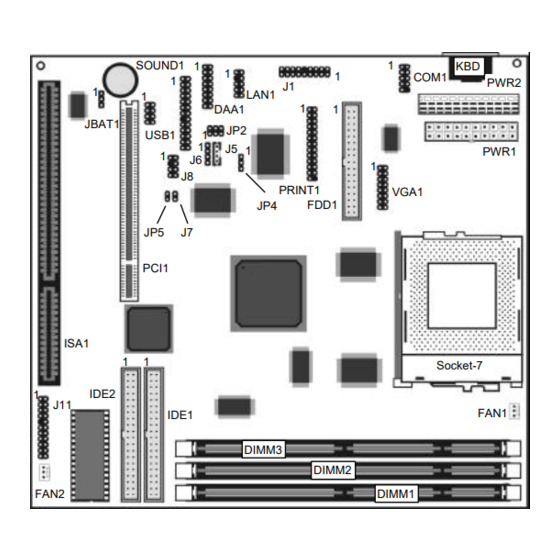
Page 12: Mainboard Components
Chapter 2 Mainboard Components Use the diagram below to identify the major components on your mainboard. SOUND1 COM1 PWR2 LAN1 DAA1 JBAT1 USB1 PWR1 PRINT1 VGA1 FDD1 PCI1 ISA1 Socket-7 IDE2 FAN1 IDE1 DIMM3 DIMM2 FAN2 DIMM1... -
Page 13: Install The Processor
Install the Processor Install the Processor This mainboard is installed with a socket-7, and so it may be installed with any of the socket-7 processors including the Intel P55C (MMX) series, the Cyrix/IBM 6x86L/6x86MX/MII series, the AMD K6/K6-2/K-III series, the IDT C6/Winchip 2/2A series. The mainboard supports system bus speeds of 60, 66, 75, 83, 90, 95, 100 MHz. -
Page 14: Install Memory
Chapter 2 2. On the socket-7 processor, identify the pin-1 corner by noting that it has a slight bevel. 3. On the socket-7, identify the pin-1 corner. The pin-1 corner is on the same side as the locking lever, closest to the top of the lever when it is in the locked position. -
Page 15: Set The Jumpers
Set the Jumpers You can install any size of memory module from 16 MB up to 256 MB, so the maximum memory size is 3 x 256 MB = 768 MB. The edge connectors on the memory modules have cut outs, which coincide with struts in the DIMM slots, so the memory modules can only be installed in the correct way. -
Page 16: Jumper Jp2: Fax/Modem & Audio System Enable/Disable Jumper
Chapter 2 Function Jumper Setting Normal Operation Short Pins 1-2 Clear CMOS memory Short Pins 2-3 Note: The mainboard ships with this jumper in the CLEAR position so you must change this jumper to NORMAL. Jumper JP2: Fax/Modem & Audio System Enable/disable Jumper. -
Page 17: Jumper Jp5: Spdif Voltage Out Selector
Install the Mainboard Jumper JP5: SPDIF Voltage Out Selector. This 2-pin jumper lets you select the voltage for the output of the SPDIF digital audio connector on the mainboard. Function Jumper Setting 5 Volts Short Pins 1-2 0.5 Volts Open Pins 2-3 Install the Mainboard Install the mainboard into the system chassis. -
Page 18: Install The Extension Brackets/Options
Chapter 2 If you are using a case with an AT power supply, connect the power cable from the AT power supply unit to the power connector PWR2 on the mainboard. If your case has a chassis cooling fan, connect the cable from the fan to the fan power supply on the mainboard FAN2. -
Page 19: Audio Ports And Game/Midi Port Extension Bracket
Install the Extension Brackets/Options The modules and extension brackets are used to transmit features on the mainboard to external connectors that can be fixed to the system chassis. Follow the steps below to install the extension brackets. Note: All the ribbon cables used on the extension brackets carry a red stripe on the pin-1 side of the cable. -
Page 20: Serial/Parallel Ports Extension Bracket
Chapter 2 Serial/Parallel Ports Extension Bracket This bracket has one serial port - COM1 (9-pins) and one parallel port – LPT1 (25pins). COM1 Header PRINT1 Serial Port COM1 Parallel Port LPT1 Serial/Parallel Ports Extension Bracket 1. On the mainboard, locate the headers COM1 and PRINT1 for this bracket. -
Page 21: Vga Extension Card
Install the Extension Brackets/Options VGA Extension Card The VGA extension card has a 15-pin connector for an external monitor cable. VGA1-VGA Header VGA Extension Card 1. On the mainboard, locate the VGA1 header for this bracket. 2. Plug the cable from the bracket into the VGA1 header. 3. -
Page 22: Lan Network Adapter Extension Bracket
Chapter 2 LAN Network Adapter Extension Bracket This bracket supports an RJ45 network connector and connects to the built in LAN header LAN1 on the mainboard. LAN1 LAN Header LAN Extension Bracket 1. On the mainboard, locate the LAN1 header for this bracket. 2. -
Page 23: Fax/Modem Daa Module
Install the Extension Brackets/Options Fax/Modem DAA Module The Fax/Modem DAA module plugs directly into the mainboard adjacent to an expansion slot in the system chassis. When you remove the blanking plate from the system chassis, you can access the LINE and TEL RJ11 connectors on the metal edge of the Fax/Modem DAA module. -
Page 24: Optional Digital Audio Extension Bracket
Chapter 2 Optional Digital Audio Extension Bracket This bracket has two RCA jacks for digital audio in and digital audio out, and an auxiliary jack for a stereo line-in device. J8 SPDIF Header Stereo Line-in SPDIF In SPDIF Out Digital Audio Extension Bracket 1. -
Page 25: Optional Atx Form Card
Install the Extension Brackets/Options Optional ATX Form Card This ATX Form Card provides a mini-DIN PS/2 port for infrared, one mini-DIN port for a PS/2 mouse. In addition it has two USB (Universal Serial Bus) ports. J1-ATX Header USB1 Infrared Port PS/2 Mouse Port USB Ports... -
Page 26: Install Other Devices
Chapter 2 Install Other Devices Install and connect any other devices in the system following the steps below. FDD1 IDE2 IDE1 Floppy Disk Drive The mainboard ships with a floppy disk drive cable that can support one or two drives. Drives can be 3.5” or 5.25” wide, with capacities of 360K, 720K, 1.2MB, 1.44MB, or 2.88MB. -
Page 27: Internal Analog Sound Connections
Install Other Devices If you want to install more IDE devices, you can purchase a second IDE cable and connect one or two devices to the Secondary IDE channel connector IDE on the mainboard. If you have two devices on the cable, one must be Master and one must be Slave. Internal Analog Sound Connections If you have installed a CD-ROM drive or a DVD drive, you can connect the sound output of the drive to the built-in sound system. -
Page 28: Expansion Slots
Chapter 2 Expansion Slots This mainboard has one PCI 32-bit expansion slots and one 8/16- bit ISA slot. PCI1 ISA1 Use the PCI slot to install a 32-bit PCI expansion card. Use the ISA slot to install a legacy 8/16-bit expansion card. Installing an Expansion Card 1. -
Page 29: Chapter 3 Bios Setup
Chapter 3 BIOS Setup Introduction The BIOS setup utility stores information about your computer such as the date and time, the kind of hardware you have installed, and so on. Your computer uses this information to initialize all the components at boot-up time, and make sure that everything runs smoothly. -
Page 30: Running The Setup Utility
Chapter 3 Running the Setup Utility Each time your computer starts, before the operating system is booted, a message appears on the screen that prompts “Press DEL to run SETUP”. When you see this message, press the Delete key and the Main Menu page of the setup utility appears on your monitor. -
Page 31: Standard Cmos Setup Page
Standard CMOS Setup Page with a set of default values. Press F7 to install the setup utility with a set of high-performance values. Standard CMOS Setup Page Use this page to set basic information such as the date and time, the IDE devices, and the diskette drives. -
Page 32: Bios Features Setup Page
Chapter 3 Set it to EGA/VGA. Halt On This item determines what kind of errors are sufficient to halt the system. BIOS Features Setup Page Use this page to set more advanced information about your system. Take some care with this page. Making changes can affect the operation of your computer. - Page 33 BIOS Features Setup Page Swap Floppy If you have two floppy diskette drives installed, Drive you can use this item to change the drive letter assignments so that drive B becomes drive A. Boot Up Floppy If you enable this item, the system checks the Seek tracks on the floppy drives at boot time.
-
Page 34: Chipset Features Setup Page
Chapter 3 Chipset Features Setup Page This page sets some of the timing parameters for your system. Before making changes to this page, you must ensure that your hardware supports the new values. Bank 0/1 2/3 4/5 These three items set the timing parameters for DRAM Timing the memory that you have installed. -
Page 35: Power Management Setup Page
Power Management Setup Page AGP Aperture Size This item defines an aperture size for an AGP graphics adapter. It defines the section of the PCI memory address space reserved for graphics. Onboard USB Enable this item if you intend using the USB Function ports that are integrated on this mainboard. - Page 36 Chapter 3 Power Use this item to enable or disable power Management management. If you set to Max Saving, the system powerdown timeouts are short. If you set to Min Saving, the powerdown timeouts are longer. If you set to User Define, you can set the powerdown timeouts manually using the items below.
- Page 37 Power Management Setup Page PWRON After PW- Use this item to set a system power state when Fail power restores after sudden AC power loss. If this item is enabled, any video activity can resume the system from a software powerdown or a power saving mode.
-
Page 38: Pnp/Pci Configuration Page
Chapter 3 PNP/PCI Configuration Page This page sets some of the parameters for devices installed on the system PCI bus, and devices that use the system plug and play capability. PNP OS Installed Enable this item if you are using an O/S that supports Plug and Play such as Windows 95 or Resources This item lets you select for Automatic or... -
Page 39: Load Best Performance Defaults
Load Best Performance Defaults PCI Master 0 WS This item defines a timing parameter for the PCI Write bus. Leave this item at the default value. PCI Delay This item can be enabled if the system has an Transaction embedded 32-bit write buffer to support delay transaction cycles. -
Page 40: Cpu Pnp Setup & Hardware Monitor Page
Chapter 3 CPU PnP Setup & Hardware Monitor Page This page uses Plug and Play technology to setup your system for the kind of CPU you have installed. This page appears blank below because it does not have defaults. CPU Type These two items show the kind and core CPU Core Voltage voltage of CPU that is installed in your system. -
Page 41: Integrated Peripherals Setup Page
Integrated Peripherals Setup Page Integrated Peripherals Setup Page This page sets some of the parameters for peripheral devices installed on the system. OnChip IDE Use this item to enable or disable the onboard Channel0 Primary IDE channel. OnChip IDE Use this item to enable or disable the onboard Channel1 Secondary IDE channel. -
Page 42: Password Settings
Chapter 3 OnBoard IR Port Use this item to set an address for an optional infrared port. If you set an address or use the Auto setting, a new item appears called UART 2 Mode. Use this item to set the Infrared protocol. -
Page 43: Save And Exit Setup
Save and Exit Setup the device and proceed to the next device. Press Y, then Enter to tell the system to auto-detect the device. Save and Exit Setup Highlight this item and press Enter to exit the Setup utility without saving any changes that you have made. -
Page 44: Chapter 4 Software & Applications
The IDE Bus Master Drivers allows the system to properly manage the IDE channels on the mainboard. You only need to install an IDE driver if you are running Windows 95. ♦ Windows 95/98 – D:\IDE\M585LMR\WIN9X\SETUP.EXE ♦ Windows NT4.0 – D:\IDE\M585LMR\NT4 USB Driver The USB Driver allows the system to recognize the USB ports on the mainboard. -
Page 45: Video Driver
♦ Windows 95 (Chinese) – D:\USB\CUSBSUPP\CUSBSUPP.EXE Video Driver The video drivers are available for Windows 95/98 and Windows NT. Look for the folders in: ♦ D:\VGA\M585LMR Sound Driver The Sound driver allows the system to generate optimal sound effects. This driver is available for: ♦... -
Page 46: Lan Driver
Chapter 4 LAN Driver The LAN driver is required by the onboard LAN adapter. D:\LAN\Davicom9102 Modem Driver The Modem driver is required by the onboard modem module. SuperVoice is a suite of modem applications for data and voice transmissions. D:\MODEM\8738\Win9x D:\MODEM\SuperVoice\ Media Ring Talk Software MediaRing Talk provides an internet telephone for the onboard... -
Page 47: The Four Speakers System
The Four Speakers System audio functions through a user interface that is as simple to use as a home stereo system. We recommend that you use the System Mixer in the Audio Rack software to control your computer’s audio volume, recording device and the recording gain. -
Page 48: Mixer Setup
Chapter 4 Mixer Setup There is a 4-speakers option in the Volume Control of the Mixer when you are setting up the PCI Audio Application. Click on the 4 SPK icon to enable this option. This means that the output to the rear speakers is sent through the Line-in/Rear jack.
Need help?
Do you have a question about the M585LMR and is the answer not in the manual?
Questions and answers