Table of Contents
Advertisement
IMPORTANT:
Read Before Using
Operating/Safety Instructions
Consignes de fonctionnement/
sécurité
Instrucciones de funcionamiento
y seguridad
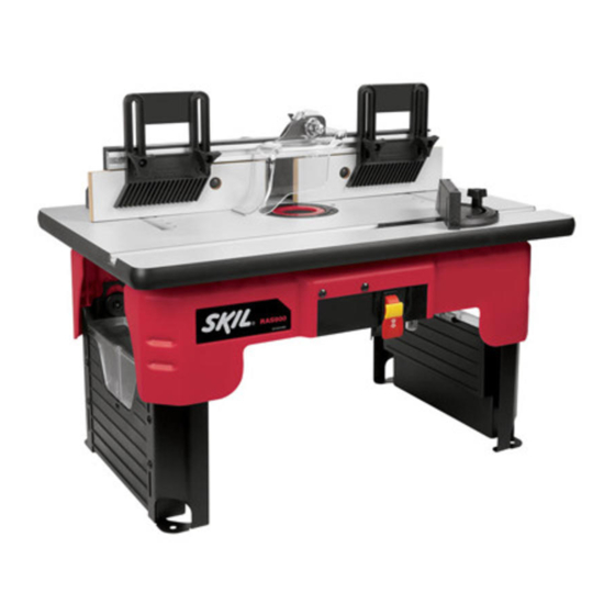
RAS900
Renseignement des consommateurs
Información para el consumidor
Toll-Free Number:
1-877-SKIL999 (1-877-754-5999) http://www.skil.com
For English
See page 2
IMPORTANT :
Lire avant usage
Consumer Information
Appel gratuit :
Número de teléfono gratuito:
Parlez-vous français?
Voir page 34
IMPORTANTE:
Leer antes de usar
¿Habla español?
Ver página 67
Advertisement
Table of Contents

Related Manuals for Skil RAS900


Summary of Contents for Skil RAS900
- Page 1 Instrucciones de funcionamiento y seguridad RAS900 Consumer Information Renseignement des consommateurs Información para el consumidor Toll-Free Number: Appel gratuit : Número de teléfono gratuito: 1-877-SKIL999 (1-877-754-5999) http://www.skil.com For English Parlez-vous français? ¿Habla español? See page 2 Ver página 67 Voir page 34...
-
Page 2: Important Safety Information
Table of Contents IMPORTANT SAFETY INFORMATION ..... 2–6 Router Table Setup ....11–19 Parts List . -
Page 3: Tool Use And Care
Personal Safety preventive safety measures reduce the risk of starting the tool accidentally. Stay alert, watch what you are doing, and use Keep guards in place. Maintain the guards common sense when operating a power tool. in working order and in proper adjustment and Do not use tool while tired or under the alignment. - Page 4 Additional Safety Warnings for Router Tables shifting unexpectedly while in use, resulting in Insert rings are meant to reduce the gap property damage or serious personal injury. between the cutting diameter of the bit and the table so that workpieces maintain full support Disconnect the router from the power of the table while routing.
- Page 5 Push sticks, featherboards, and jigs eliminate When servicing the tool, use only the need to hold the workpiece near the recommended SKIL replacement parts. spinning bit. Follow instructions in the Maintenance Never let go of the workpiece when routing section of this manual.
- Page 6 Important Information About Extension Cords RECOMMENDED SIZES OF EXTENSION An extension cord with adequate size conductors CORDS FOR 120-VOLT ALTERNATING that is capable of carrying the current for CURRENT TOOLS your tool must be used. This will prevent excessive voltage drop, loss of power, or overheating.
-
Page 7: Parts List
Parts List Refer to Parts List below and on pages 8–10. • • In order to simplify handling and to minimize If ANY of the parts are any damage that may occur during shipping, missing, DO NOT attempt your router table comes mostly assembled. to assemble, install, or use your router table Repositioning of some parts will be required. - Page 8 Parts List Table Assembly Components Switch Assembly Guide Pin Components Bit Height Gauge Tabletop Inserts Fence Components Fence Components Featherboard Miter Gauge...
- Page 9 Parts List Key No. Description Quantity ITEMS NOT ILLUSTRATED Operating/Safety Instructions MISCELLANEOUS FASTENERS (installed or bagged) Spacer #10-32 KEPS Nut #10-32 Flat Washer #8-32 x 1/2 Pan-Head Machine Screw (router mounting) #10-16 x 1/2" Pan-Head Screw #10-24 x 1/2" Pan-Head Machine Screw (router mounting) #10-24 x 1"...
- Page 10 Parts List Miscellaneous Fasteners (cont.) (38) #10-32 x 3/8" (39) #10-32 x 1/2″ (40) #10-32 x 5/8" (41) #10-32 x 7/8" Truss-Head Screw Pan-Head Machine Truss-Head Screw Countersunk-Head Screw (for Guide Pin Guard) (for Miter Channel) Screw (for Router) (for Switch Box) (42) 5/16-18 x 1/2″...
-
Page 11: Router Table Setup
Router Table Setup PREPARING THE ROUTER TABLE FOR USE Lift router table only by the table edges. Lifting table by any other surface could cause personal injury. HELPFUL TOOLS TO HAVE ON HAND • #1 and #2 Phillips screwdrivers (not included) •... -
Page 12: Removing Fence Assembly
Router Table Setup REMOVING THE FENCE ASSEMBLY FIG. 3 (Fig. 3) The fence for your router table comes fully assembled with the adjustable jointing fence and overhead guard already in place. The fence assembly is secured to the bottom of the table for shipment and storage. -
Page 13: Attaching Quick-Clamp Router Mounting Plate
• Other manufacturers routers are outside 4. Refer to the mounting plate guide (Fig. 7) on of SKIL s control. Changes made to these page 14 and align the appropriate mounting routers may affect the compatibility to the plate holes for your router to the router base fasteners specified and/or supplied with holes. -
Page 14: Attaching Quick-Clamp Router Mounting Plate
#10-24 x 1/2" Pan-head Phillips machine screws (36) 7529 plunge router, and 892–895 series (fixed base only) Ryobi 163K 5/16-18 x 1/2" Pan-head Phillips machine screws (42) Skil 1810, 1815, 1820, 1825 #10-32 x 1/2" Pan-head Phillips machine screws (39) -
Page 15: Installing Quick-Clamp Mounting Plate/Router
Router Table Setup INSTALLING THE QUICK-CLAMP FIG. 8 MOUNTING PLATE AND ROUTER TO THE ROUTER TABLE (Figs. 8–11 and Detail 11) Before using the router table, verify that the router is securely clamped in the router table base. While working, periodically check the router base fasteners clamping tightness. -
Page 16: Installing Fence Assembly
Router Table Setup INSTALLING THE FENCE ASSEMBLY FIG. 12 (Fig. 12 and Detail 12) The fence comes assembled. Step 1 refers to reassembly, if necessary; otherwise, go to Step 2 if already assembled. 1. Install spacers (31) on square-head bolts (47) (Detail 12). - Page 17 Router Table Setup TOOL BOXES (Fig. 14) FIG. 14 Your router table (A) comes with two tool boxes (9) with hinged covers. The tool boxes are permanently mounted to the left and right leg assemblies (8 and 10). Both tool boxes have hinged covers with latching tabs on the front.
- Page 18 Router Table Setup METHOD 2 (Fig. 16) FIG. 16 1. Set the router table (A) on a workbench or other stable and sturdy surface with the FRONT (switch side) of the router table facing towards you. 2. While holding the router table in the desired position, mark the location of the four mounting holes (one in each leg [8 and 10]).
- Page 19 Router Table Setup OVERHEAD GUARD ASSEMBLY Spacer (Fig. 19) FIG. 19 The overhead guard assembly (18) comes preinstalled on the fence assembly. Some routing applications will require you to remove this guard. 1. Loosen and remove clamping knob (21) on the top back of the fence assembly (C).
-
Page 20: Router Table Operation
GENERAL INFORMATION GROUNDING CONDUCTOR TO A LIVE TERMINAL. The power switch is designed for use with most SKIL Router Tables. It provides the Check with a licensed electrician if the convenience of an ON (RESET)/OFF switch grounding instructions are not completely... - Page 21 Router Table Operation INSTALLING THE SWITCH BOX FIG. 21 (Fig. 21) If the switch box assembly (14) does not come preinstalled to the front table housing (6), use the following instructions to attach the switch box. 1. Place two #10-32 x 5/8" truss-head screws (40) in the holes in the front table housing opening.
- Page 22 Router Table Operation SWITCH OPERATION (Fig. 23) FIG. 23 This section explains the operation and features of the switch box assembly prior to plugging the power cord into a power outlet. The intent is to familiarize the user with the switch operation without actually turning ON the router.
- Page 23 Remove the switch from the router table and obtain a replacement switch 2. To turn the router ON, pull up the red by calling SKIL customer service at paddle to the ON position. See page 22. 1-877-SKIL999. 3. To turn the router OFF, press the red paddle to the OFF position.
-
Page 24: Using The Router Table
Router Table Operation USING THE ROUTER TABLE ATTACHING AND USING A WET/DRY VACUUM Operating the router table Before connecting vacuum without a wet/dry vacuum to router table switch box, ensure that the vacuum switch is OFF, and can result in an excessive buildup of sawdust and wood chips under the fence assembly and that the router table switch box is unplugged. - Page 25 Router Table Operation ASSEMBLING THE FIG. 24 FEATHERBOARDS (Figs. 24–26) NOTE: The top/front side of each featherboard is marked to indicate proper feed direction. Fence Featherboard (Fig. 24 and 25) 1. Insert two 1/4-20 x 1½" carriage bolts (46) through the slotted holes in each featherboard (22).
- Page 26 Router Table Operation ROUTING USING FEATHERBOARDS FIG. 27 (Fig. 27) DIRECTION Featherboards are helpful in controlling the workpiece while routing and assisting in OF FEED keeping the workpiece flat on the tabletop. The tabletop featherboard combined with the fence featherboard helps keep the workpiece pressed against the fence and tabletop.
- Page 27 Router Table Operation For accuracy in routing and improved control, the FIG. 28 workpiece should be held against the router table fence when routing. ADJUSTING THE FENCE FACEPLATES (Fig. 28) The right and left fence faceplates are attached to the front face of the router table fence and can be adjusted inward or outward from the router bit to allow proper clearance for different-sized bits.
- Page 28 Router Table Operation ADJUSTING DEPTH AND HEIGHT OF 21 Behind fence CUT (Fig. 30 and Detail 30) on base SCRAP WOOD FIG. 30 1. Select a board that is smooth and straight, with good square edges. 2. Mark lines “A” and “B” on the end of the board, as shown in Detail 30.
- Page 29 Router Table Operation FULL EDGE CUTTING OR JOINTING FIG. 31 (Figs. 31–33) For maximum strength and accuracy, boards that are to be joined together should be smooth and true. The edges should be true to the workpiece surface. You can true the edges using the router table with a straight bit.
- Page 30 Router Table Operation EDGE CUTTING WITH NONPILOTED FIG. 34 ROUTER BITS (Figs. 34 and 35) FENCE Disconnect the router FACING from the power supply before making adjustments or changing accessories. Such precautionary safety ROUTER BIT measures reduce the risk of unintentional tool operation.
- Page 31 Router Table Operation EDGE CUTTING WITH PILOTED CLEARANCE FIG. 36 ROUTER BITS (Figs. 36 and 37) BETWEEN FENCE AND Disconnect the router from the power supply before making adjustments or changing ROUTER BIT accessories. Such precautionary safety PILOT measures reduce the risk of unintentional tool operation.
- Page 32 Router Table Operation GROOVING, FLUTING, AND FIG. 38 VEINING (Figs. 38 and 39) LOCATION OF CUT Disconnect the router FENCE from the power supply FACING before making adjustments or changing accessories. Such precautionary safety SURFACE measures reduce the risk of unintentional FORMING tool operation.
-
Page 33: Using Starter Pin For Curved Work
Router Table Operation USING THE STARTER PIN FOR FIG. 40 CURVED WORK (Figs. 40 and 41) The starter pin (26) is used instead of the fence for operations that involve routing curved workpieces. It should be used only with bits that have pilot bearings. Thread the starter pin (26) into the threaded hole in the table (1) and tighten securely with a slotted screwdriver (Fig.
Need help?
Do you have a question about the RAS900 and is the answer not in the manual?
Questions and answers