Table of Contents
Advertisement
Quick Links
Advertisement
Table of Contents

Related Manuals for marklin 60215


Summary of Contents for marklin 60215
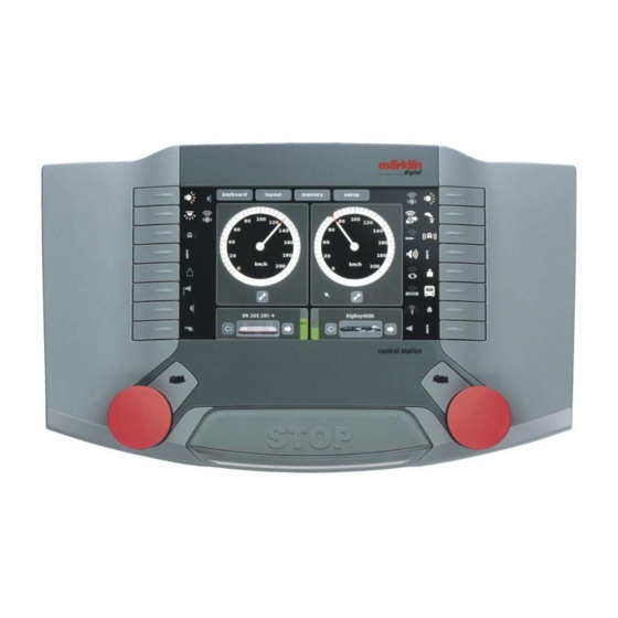
- Page 1 Central Station Controlling Switching Running...
- Page 2 Central Station Stylus = Operating step(s) Märklin Switch to Switch to Switch to Switch to = Operating step(s) DCC memory setup keyboard layout Switch to control Underside of Unit Function Buttons 0 - 7 Function Buttons Function Symbols 0 - 7 8 - 15 Function Symbols Locomotive set up...
- Page 3 Getting Set Up and Started Preparations Connections to the Layout The following components are required to get started: 60 VA power-supply unit, connecting cable between the power-supply unit and the Central Station, Connections to C Track or Connections to K Track or 1 Gauge feeder connection and/or connecting wires between the Central Station and the track layout, rolling stock and/or solenoid The only possible connections are those shown! accessories.
- Page 4 Getting Set Up and Started Page 39 => Selecting and Running a Locomotive Registering mfx locomotive Running a Locomotive Function switch Data from the mfx locomotive completely read in. Confi rm The mfx locomotive is ready to run and can already be operated. If it becomes necessary, we re- commend that the locomotive be added to in the locomotive list as...
- Page 5 Getting Set Up and Started Selecting and Running a Locomotive Loading the Basic Confi guration for DCC Running a Locomotive Function switch Do Reset_DCC. After that the basic con- fi guration for the Central Station is set to DCC. This facilitates entering locomotives and turnouts.
- Page 6 This Märklin product is not watertight. Malfunctions can occur if there is high humidity or if moisture Outlet: Connections for a Central Station (60213/60214/60215), the Terminal 60125 or from the Connect 6021 gets inside the housing. The corrosion of the internal mechanism and electronics can lead to irrepara- ble damages.
- Page 7 Control...
- Page 8 Locomotives and powered units can be entered, run, and managed with the Control. Locomotive with an mfx Decoder Registering and/or taking into the locomotive list. Selecting and Running Place your locomotive with an mfx decoder on the programming track. This can also be done while the layout is in operation.
- Page 9 Entering: Ö Page 45 New locomotive manually: Introduction and Preparation Ö Page 46 Locomotive with DIP Switches Ö Page 47 Programmable Locomotive Online Help small or Opens Keypad large Locomotive Description Select Icon Whenever you see this Symbol the Help function is available Selection for for you to use and will take the Display...
- Page 10 With DIP Switches Programmable locomotive Ö Page 47 Enter locomotive name: ex. Class 03. If the locomotive is standing on the program- ming track, you can read out the address for it. Select icon. enter a decoder address. You can do other settings that infl uence the locomotive‘s running characteristics when controlled with the Central Station.
- Page 11 Confi rm. The locomotive has been taken into the locomotive list. You can do other settings that infl uence the locomotive‘s running characteristics when controlled with the Central Station. The settings can be done in the fi elds with “-“ or “+“. In our example: acceleration and braking delay as well as the speedometer.
- Page 12 Confi guring a Locomotive Adding to / changing symbols, functions, and settings. This function can be used for all types of decoders. However, only those settings and functions available on the computer can be processed. In the example of a locomotive with an mfx decoder we are showing you the multifaceted possibilities You now have the possibility for these settings.
- Page 13 The shuttle train is now imme- diately active; the locomotive can now be used only for this. Check The shuttle train is set up and can be activated at anytime. The locomotive can be used universally. Confi rm deactivated activated Changing or Adding Function Symbols.
- Page 14 4. Editing a selected function confi rm or reject You can change functions or assign characteristics to the functions (dim, blink, The data are transferred etc.). only for programmable or mfx decoders. Decoders with DIP switches are only taken into the loco- motive list.
- Page 15 Functions when the locomotive is stopped or running Programming On The Main (POM) Here you can set up a function that works when Programming On The Main (POM) is a special form of programming in which the locomotive is the locomotive is stopped (S) or is running (F). programmed while it is running;...
- Page 16 Entering an M.U. Consist Add the fi rst locomotive in the m.u. consist. An m.u. (multiple unit) consists of at least 2 locomotives. You can however also have several locomotives in a consist. The number of locomotives is limited by the current draw for users in the power consumption area.
- Page 17 The motive power consist has been taken into the The motive power consist can locomotive list. now be taken into the Control. The locomotive or m.u. consist is removed from the locomotive list and is no longer available for use. It must be entered again. If you have not previously carried out a data protection procedure (backup), the data just deleted are...
- Page 18 Keyboard...
- Page 19 The Keyboard enables you to control and manage all turnouts, signals, turntables, and transfer tables; a total of 320 or 2,048 addresses are available for use. Controlling Standard Turnouts and Signals Turntable All addresses for the protocol being used are available immediately after the Central Station has booted up and can be controlled using the standard control surface (see illustrations).
- Page 20 Selecting the Desired Address Enter a designation, ex. DSS-9. Check the setting for the turnout decoder. Confi rm entry Any programming of your DCC turnout decoder must be done according to the instructions for that decoder.
- Page 21 Checking Accessory Function 15.1 If the turnouts/signals are connected to k 83 decoders (item nos. 6083 or 60830) and the turnout/signal setting does not correspond to the display, then the blue wires for the connection in question must be swapped. If the solenoid accessory does not operate despite the correct address, please check the wires at the track connection.
- Page 22 Programming Professional Quality Color Light Signals. With a signal with more than 2 aspects other signal aspects will alternately blink. The individual steps for these signals can be found in examples further down in the text. No locomotives may be run during the programming procedure. Please note that the programming procedure will be stopped if there are no entries made within 30 seconds.
- Page 23 Layout...
- Page 24 Setting up a Layout. The Layout level of control on the Central Station simplifi es setting up and operating solenoid accessories and routes on a model railroad later on. After a Layout has been set up, turnouts, signals, or routes can be activated by pressing on a symbol. Several Layout pages can be constructed in a Central Station. We recommend that you set up the appropriate items on your keyboard before setting up the Layouts page.
- Page 25 Delete Rotate Adding a Route: symbol symbol In our example there is only 1 route available for use. If several routes are available, then the desired route can be selected with the arrow button. Confi rm selection. Information about solenoid accessory and change.
- Page 26 Enter the name into the track diagram, example: Track 1 If the route is also to be operated by means of an S 88 contact, the latter can also be placed in the Layout. Confi rm selection An S 88 contact has been placed in the Layout.
- Page 27 Memory...
- Page 28 Setting up a Route. The “Memory“ part of the Central Station is used to set up and operate routes on a model railroad. Sixteen Memory windows are available for this function. We recommend that you set up the appropriate items on your Memorys before setting up the Layouts page. Routes are used so that you can activate several solenoid accessories with the press of a single button.
- Page 29 Controlling a Route. Add a solenoid accessory to the route. Start the route. The route is now in the operation mode. You can add the solenoid accessories from different keyboards to a route. The route is now You do not have to adhere in operation.
- Page 30 Setup...
- Page 31 Setup allows you to adjust the reproduction of data, backup of data, update, reboot, shut down, calibrating, and settings for the Central Station. Setup 2nd Central Station 1st Central Station prog prog 60123 Slave cable (Not included with a Central Station). Switch to the processing mode.
- Page 32 Information about Devices Connected to the Central Station Mobile Station 60652 You can get information about After you have plugged the Mobile Station in, current, voltage, and temperature it will register itself automatically. After the for the Booster or 2nd controller registration procedure is over, locomotives that you have selected.
-
Page 33: System Architecture
System Architecture 60061/60101 60061/60101 60061/60101 60213/60214/60215 60213/60214/60215... - Page 34 Wireless drive and control is possible with the iPod Touch ®, iPhone ® or iPad ® with a Memory => 32 GB and a wireless router. How does this work? Get yourself the “Märklin Mobile Station” App (English abbreviation for application) in the App StoreSM and install this application on your controller. Then connect your Central Station to your WLAN router.
- Page 35 Appendix: Available Symbols Acceleration/braking delay Table lamps Era III Rear Telex coupler instead of symbol Blank Pump Table lamps Era II Front Telex coupler instead of symbol End light(s) Interior lighting Brake squealing Grate being shaken Rear pantograph instead of symbol Relay steps Rail joints sounds Front pantograph...
- Page 36 Gebr. Märklin & Cie. GmbH Stuttgarter Straße 55-57 73033 Göppingen 169625/0211/Ha1Gm Deutschland Änderungen vorbehalten www.maerklin.com © by Gebr. Märklin & Cie. GmbH...
Need help?
Do you have a question about the 60215 and is the answer not in the manual?
Questions and answers