
Related Manuals for AN-Motors ASG600/3KIT

Summary of Contents for AN-Motors ASG600/3KIT
- Page 1 РУКОВОДСТВО Installation and operation manual ПО МОНТАЖУ И ЭКСПЛУАТАЦИИ Sets series ASG/KIT for automation of garage doors ASG600/3KIT ASG1000/3KIT ASG1000/4KIT...
-
Page 2: Table Of Contents
CONTENTS General information and safety measures………… …………………..PRODUCT DESCRIPTION……………………………………………………………. 2.1. Scope of supply ………………………………………………………………..…… 2.2. Technical characteristics ………………………………………………………….. Installation preparation ………………………………………………………… 3.1. Preliminary inspection ………………………………………………………. 3.2. Tools and materials for installation…….. …………………………………. 3.3. Preliminary works …………………………………………………………………… Installation ………………………………………………………………………………….. 4.1. Assembling of the drive rail…. ………………………………………………… 4.2. -
Page 3: General Information And Safety Measures
1. GENERAL INFORMATION AND SAFETY MEASURES This manual contains important information about safety measures. Before the mount- ing it is necessary to make a careful study of the mentioned information. Keep this manual for further application! Installation, connection, final testing of the equipment, commissioning and technical support must be performed by qualified and trained specialists. -
Page 4: Product Description
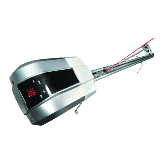
The set for garage doors automation (further - Set) includes the electric drive (further - Drive) with the drive rail and serves for automation of the balance system of garage doors. Set ASG600/3KIT and set ASG1000/3KIT contain the rail ASGR3. Set ASG1000/4KIT contains the rail ASGR4. -
Page 5: Technical Characteristics
2.2. Technical characteristics The mentioned characteristics are stated for the environment with 20 ºС (±5 ºС). Table 2. Technical characteristics of the drive Value Parameter ASG600/3KIT ASG1000/3KIT ASG1000/4KIT Supply voltage, В 230 (±10%) Supply frequency, Hz Maximal driving force, Н... -
Page 6: Installation Preparation
3. INSTALLATION PREPARATION 3.1. Preliminary inspection Before the installation of the set it is necessary to: Check all the elements and materials on the possibility of their application and correspondence to the current regulations. Make sure that door construction is suitable for automation. The set cannot be applied in doors with a wicket or pedestrian zone. -
Page 7: Preliminary Works
3.3. Preliminary works Before the installation: Define the approximate position of every component in the drive system; Define the plan according to which the connection of all electrical devices in the drive system will be performed; Make sure there are all required tools and materials; Define the extremes of the wire and lay cables in the places for components installation;... - Page 8 35º… 55º 15º… 30º Pic. 2. Set installation...
-
Page 9: Installation Of The Drive On The Rail
а б Pic. 3. Manual unblocking of the carriage In the process of unblocking there can be uncontrolled movement of doors: - if the door spring are loose or broken; - if the doors are not balanced; - if the doors are opened manually the carriage can collide with the drive (during build- ing works limit the doors run in the opening direction);... -
Page 10: Connection Of Carriage And Door Curtain
Position the fixing bracket of the rail 12 (view F, Pic. 2) and the bent fixing strip 22 (de- scribed above) on the rail at a place ensuring the highest rigidity of the rail (for example, at a distance 1/3 of the rail length from the door passage). Connect the fixing bracket of the rail and the fixing strip using two bolts 14 and two nuts 18. -
Page 11: Photo Cells Installation
+24V PE GND PB фотоэлементы Photo cells кнопка Control button управления аккумулятор Accumulator Pic. 4. Electric supply system 5.1. Photo cells installation To ensure the security the drive may have photo cells. Output circuit of the receiver (RX) must be connected with the terminals «PE» and «GND». Power circuit of the receiver (RX) and transmitter (TX) of photo cells are connected with the terminals «+24V»... -
Page 12: Drive Connection To The Electric Network
5.5. Drive connection to the electric network During the first connection of the drive to the electric network: Make sure that the rail carriage is blocked. Connect the plug of the drive feeding cable with the outlet of supply network. Immediately after connection of the plug and the outlet there will be a short light from the lamp (lightening), the indicator on the drive control panel (Pic. -
Page 13: Adjustment Of Working Modes
Table 5. Adjustment of final positions of door opening/closing Action Indicator Press and hold button «SET» for 5 seconds When you see the indicator «Р1» release the button and press once again «SET» without holding it When you see the indicator «ОР» using buttons «UP» and «DOWN» move the door leaf to the final opening position. -
Page 14: Programming Of Control Boards
Press and hold button «SET» for 5 seconds When you see the indicator «Р1» release button «SET» Using buttons «UP» and «DOWN» choose the mode «РЗ», after than press button «SET» Using buttons «UP» and «DOWN» choose «HI» (photo elements are ac- tive), or «НО»... -
Page 15: Testing And Commissioning
А - Control buttons В – electronic blocking buttons С – LED Pic. 6. Radio control board Таблица 7. Запоминание и стирание пультов радиоуправления Action Indicator A) Board entering in the memory of the control unit Press button «CODE» When you see the indicator «Su» press 1...2с chosen button on the con- sole (one of the buttons А, pic. -
Page 16: Commissioning
Repeat the cycle “opening-closing”. Make sure that the doors move in the required direc- tion, door curtain must move evenly without any changes of speed. The movement must slow down at approximately 200mm height from the final position. Make sure that the illuminating lamp is “lit” when the drive works and “goes out” after 3 minutes after final shut-off. -
Page 17: Defects And Recommendations On Their Elimination
The drive is designed for operation in dry premises and cannot be applied in acid, salty and highly explosive environment. The drive system must be examined by service maintenance specialists regularly to ensure ef- fective and safe operation. Planned maintenance must be carried out in accordance with the current regulations stated in the present manual observing safety measures. -
Page 18: Storage, Transporting And Utilization
Table 8. Defects and recommendations on their elimination Defect Possible reason Recommendations Drive does not work (indica- Electric supply is cut off Check the voltage in the net. tor on the control board does or safety device is fused Check and replace if necessary not show anything) the safety device (safety device parameters must correspond to... - Page 19 Certificate data Manufacturer _____________________________________ Product class _____________________________________ Factory number _____________________________________ Information about the client (customer) ___________________________________________ ___________________________________________________________________________ ___________________________________________________________________________ name, address and telephone of the client (customer) Information about the supplier (mounting company) ________________________________ ___________________________________________________________________________ ___________________________________________________________________________ name, address and telephone of the supplier (mounting company) Mounting questionnaire Customer (address) _________________________________________________________ ___________________________________________________________________________...
- Page 20 Registration of technical maintenance Date Works completed Customer Supplier Certificate on mounting and adjustment The set is installed and adjusted according to the stated regulations and is ready for commis- sioning. _______________________________ Date of mounting date, month, year Signature of person responsible for mounting _______________________________ signature _______________________________...
- Page 21 Guarantee 1. The seller guarantees functionality of the product in case all the instructions and regula- tions on its usage and installation by the Organization authorized by the Seller are observed. 2. Warranty period is ___________________ and is calculated from ___________________________________________________________________________.
- Page 22 Notes...
- Page 23 Notes...
Need help?
Do you have a question about the ASG600/3KIT and is the answer not in the manual?
Questions and answers