Table of Contents
Advertisement
Quick Links
P 4 0 5
User's Manual
Acknowledgements
EPSON is a Trademark of Seiko Epson Corporation.
IBM is a Trademark of International Business Machines Corporation.
Proprinter is a Trademark of International Business Machines Corporation.
HP is a Trademark of Hewlett Packard Corporation.
A Publication of PSi Printer Systems international GmbH
Eiserfelder Straße 316
57080 Siegen @ Germany
Pub. No.
5112 991 19021 Juni 2001
Order No.
Great care has been taken to ensure that the information in this handbook is accurate and complete.
However, should any errors or omissions be discovered or should any user wish to make suggestions
for improving this handbook, please feel encouraged to send us the relevant details.
The contents of this manual are subject to change without notice.
Copyright © by PSi Printer Systems international.
All rights strictly reserved. Reproduction or issue to third parties in any form is not permitted without
written authorization from the publisher.
Advertisement
Table of Contents

Related Manuals for PSI P 405


Summary of Contents for PSI P 405
- Page 1 P 4 0 5 Proprinter is a Trademark of International Business Machines Corporation. HP is a Trademark of Hewlett Packard Corporation. User's Manual A Publication of PSi Printer Systems international GmbH Eiserfelder Straße 316 57080 Siegen @ Germany Pub. No.
-
Page 2: Maintenance
We certify that the equipment at issue, Type: Printer P 405 The printer P 405 fulfils the safety regulations according to UL 1950 and VDE corresponds to the law regulations ruling electromagnetic compatibility of (IEC 950) and CSA 22.2/No. 950 for computer systems. - Page 3 Operating Environment Avoid installing the printer where it is exposed to moisture or heat (eg. direct sun light). Temperature: + 10EC to + 35EC (+50EF to +95EF) Humidity: 20% to 80% Humidity with Automatic Sheet Feeder (ASF): 30% to 70% Slots and openings in the printer's housing are provided for ventilation.
-
Page 4: Table Of Contents
Table of Contents Table of Contents 2. Printer Operation ..........2-1 Control Panel . - Page 5 Table of Contents Table of Contents 3. Configuring the Printer ........3-1 Main Function INSTALLATION What means Configuration .
- Page 6 Table of Contents Table of Contents 4. Maintenance ..........4-1 Appendices Preferred Materials .
-
Page 7: Preface
Preface Preface Maintenance shows how to clean the printer and how to replace the platen and the print head. Trouble Shooting and Diagnostics About this Manual suggests how to identify and correct simple problems. This manual covers the printer in combination with an interface module (Perso- nality Module). - Page 8 Preface Conventions Used in this Guide The following conventions are used: Bold Headlines and important information. Contains special advice to facilitate handling. Note: Contains important information to prevent damage Caution: of the equipment. [ENTER] Key functions are always depicted in brackets or indicated by the symbol e.g.
-
Page 9: Getting Started
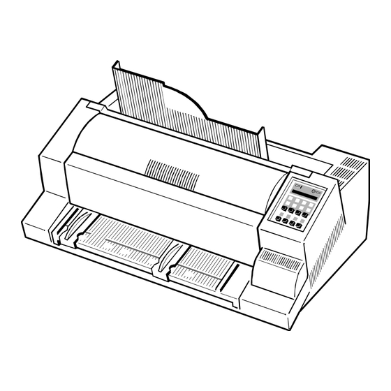
Getting Started 1. Getting Started A First Look at the Printer Before installing the printer, spend some time familiarizing yourself with the printer. - Top Cover (1) - Ribbon Cassette (2) Unpacking - Printer Base Unit(3) - Front Cover (4) - Manual Front Insertion Guide (5) - Slot for Memory Card (6) Check each item against the check list detailed below. -
Page 10: Transport Lock
Getting Started Getting Started Site Considerations Transport Lock Environment Conditions You will find a red shipping tab under the top cover (2). Install the printer in an area away from any heat source, air conditioner or strong drafts. Grasp the top cover (2) on the left and right, lift it and remove the transport locking clip (12) from the print head drive belt. -
Page 11: Installing The Personality Module
Getting Started Getting Started Installing the Personality Module The Power Supply The printer functions only in combination with an installed interface module, Mains Voltage Selection called a Personality Module (PM). In general, the mains voltage selection is determined at factory site. The illustration below shows the standard PM with a serial and parallel inter- Since an incorrect voltage selection can seriously damage the printer, please face. -
Page 12: Power On/Off Switch
Getting Started Getting Started Installing the black ribbon cassette Power ON/OFF Switch Informations about installing the 4-colour-ribbon cassette you will find in Note: The power ON/OFF switch (1) turns the printer's power supply ON or OFF. chapter 6 Options. It is recommended to use only original ribbon cassettes (part numbers in appendix H) put out by our company. - Page 13 Getting Started Getting Started 5. Position the lower mounting pin (a) on the guide to the right. Slide the cassette downward. In this position, the green ribbon feed guide touches the green plastic clip. 6. Move the cassette toward you until you hear a click on both sides. Swing the ribbon underneath the print head for the final click.
-
Page 14: Replacing The Ribbon Cassette
Getting Started Getting Started When installed correctly the ribbon cassette has a sloping position. 1.5.1 Replacing the Ribbon Cassette Note The print head may be very hot immediately after printing! Caution: 1. Lift the top cover to gain access to the ribbon cassette mountings. The print head will move to the correct position, aligned with the cut-out in the paper guide plate to facilitate the installation of the ribbon cassette. -
Page 15: Selection Of Operator Panel Language
Getting Started Getting Started Selection of Operator Panel Language Tractor The printer control panel and LCD display menu is used for the next steps. It is possible to change the language in the printer menu from English to French or Inserting Fanfold Paper for the First Time German. - Page 16 Getting Started Getting Started - Open the tractor covers (16) and insert the paper. - Pull the green tractor lock levers (12) toward you to release the tractors. - Close the tractor covers. - Lock both green tractor levels - Tighten the upper edge of the fanfold paper by slightly pushing the right - Roughly adjust the tractors (13) to the paper width, and space out the paper tractor to the right.
-
Page 17: Manual Sheet Insertion
Getting Started Getting Started - Move the left hand paper guide into the position indicated by ± • (22) on the - Select the paper source TRACTOR using either the menu selection of the printer or your software (chapter 1.9). insertion guide. -
Page 18: Paper Source Selection
Getting started Getting started 1.10 Test Printouts 1.9 Paper Source Selection There are three test printouts available. The basic selections for PAPER SOURCE are: - TRACTOR (Default, indicated by ’) - PRINT TEST 1 shows a pattern of all printable characters. Use this to check - MANUAL if the printer operates correctly. - Page 19 Getting started Getting started To start a print test: 1. Switch the printer ON (display shows READY 1 HP). Eilzustellung Norddeutsche Farbwerke KG The following identifies the keys to press and the corresponding operator Herrn Dr. Grauert Große Elbstraße 64 panel displays.
-
Page 20: Connection To A Computer
Getting started Getting started To stop the print test: 1.11 Connection to a Computer (93) PRINT TEST 1 Parallel/Serial Interface - Switch OFF the printer and computer. SELF TEST - Connect the interface cable coming from the computer to the printer's parallel (15) or serial port (16). -
Page 21: Emulation Selection
Getting started 1.12 Emulation Selection The following emulations are included in the PM Ser/Par HP: - HP (Default) in Macro 1 - IBM Proprinter XL 24 in Macro 2 - IBM Proprinter XL 24 AGM in Macro 3 - EPSON LQ / ESC/P2 in Macro 4 The default configuration is HP Emulation in macro 1. -
Page 22: Printer Operation
Printer Operation Printer Operation 2.2 Function Keys The function keys of the operator panel are grouped into two rows. The function of the key dependent on the printer operation state. Following oper- ation states are possible: - READY or BUSY 2.1 Control Panel - LOCAL The control panel... -
Page 23: Detail Description Of Keys In The Printer Operation State Ready Or Busy
Printer Operation Printer Operation After pressing one of the keys the menu-mode is - Top Row Keys Note: activated. Now the key of the top row can only be used as cursor The Quick Macro Selection mode is entered when one of the top row keys keys to move within the menu tree (right [Y], left [Z], up [[] and is pressed. - Page 24 Printer Operation Printer Operation The range within which variations can be met is - / to + / of an inch How to Use this Function (0.42 mm), where "-" is up the page and "+" is further down the page (see Preprinted paper (e.g.
-
Page 25: Meaning Of The Keys In The Local Mode
Printer Operation Printer Operation There are two possibilities for the displacement to become active: - START/STOP Key (93) - If a positive displacement is set before starting the print job the printer - turns off the STOP indicator will move the paper into the right position first and then start printing. makes the printer ready for operation - If the displacement is set during a print job, the printer prints the either starts the printout or self-test functions when selected (see... -
Page 26: To Activate The Menu
Printer Operation Printer Operation 2.3.1 To Activate the Menu: 2.3.2 To Confirm Selection: - Press - press [Y]; the confirmed value is displayed with an asterisk (’) in the last The printer is in the STOP mode, the display shows LOCAL position as shown in the picture before. -
Page 27: How To Save Settings
Printer Operation Printer Operation 2.3.3 How to Save Settings 2.4 Quick Settings The settings selected and confirmed are only active until the printer is switched The keys (94) (to select a pre-configured macro), (95), (96), and (97) are shortcuts in the menu tree. These particular selections can be off. -
Page 28: Status And Error Messages
Printer Operation Printer Operation 2.5 Status and Error Messages TEAR OFF PAPER Displayed when a switch has been initiated from currently tractor to a different The following messages are displayed if a condition exists which prevents paper source and the fanfold paper could not retreat into the parking position. normal operation of the printer. -
Page 29: Configuring The Printer
Configuring the printer 3 Configuring the Printer Display 1. Switch the printer ON READY 1 HP (93) LOCAL What is Configuring MACRO SELECT 6 This chapter describes how to use the operator panel and menu settings to set (94) up or configure your printer so that the printer and your computer system can communicate correctly with each other. -
Page 30: Buffer
Configuring the printer Configuring the printer 3.2 Standard Configuration 3.3 Explanation of the Printout (see the previous page) The standard configuration is reflected in the following printout provided that The heading PRINT OUT gives information about the VERSION of the printer's no parameters have been changed. -
Page 31: Main Function Change Macro
Configuring the printer Configuring the printer 3.4 Explanation of Individual Menu Items - PRINT OUT This function initiates a printout of the parameter settings and macro Main Functions definitions. This printout is helpful for future reference and when macros are The following main functions are available: to be changed. -
Page 32: Print Quality
Configuring the printer Configuring the printer - Print Quality - Page Length (only for fanfold paper) Three different print quality levels can be selected: Page length is expressed in terms of lines within the range of 5 to 132 lines. - Draft quality (font "Data") Any page length setting is based on six lines per inch, regardless of the - Near letter quality (NLQ displayed with the font name) - Page 33 Configuring the printer Configuring the printer - The left margin is set in / " steps, depending on the actual selection. The - The top margin indicates the first print line and is always set in steps of / ". first left margin position is / "...
-
Page 34: Paper Source
Configuring the printer Configuring the printer - Perforation Skip - Emulation If PERF. SKIP is set to YES the printer starts to print after specified top The emulation determines the set of commands available for the printer (see margin and stops printing before the bottom Margin. Programming Manual). -
Page 35: Commands
Configuring the printer Configuring the printer - $$ Commands Main-Function INSTALLATION This function causes $$ either to be printed as $$ or to activate ESC commands within an application. (If the host isn’t able to send ESC use $$ Sub-Function INTERFACE instead of ESC). - Page 36 Configuring the printer Configuring the printer - CTS MODE (Only indicated if the serial interface is selected) - Platen Gap The input signal CTS (Clear To Send) of the RS232-C This adjustment is to be seen as a correctional offset to the platen gap set by interface can be set to ignore.
- Page 37 Configuring the printer Configuring the printer - CUTTING V-POS (Vertical adjustment for tear off position) - TRACT. FF-MODE (Tractor Form Feed Mode) This parameter influence the TEAR-OFF position and can be used to EXECUTE FF means, every form feed sent to the printer will be executed. compensate mechanical tolerances which may cause a misalignment If you set IGNORE FF, only a form feed before printable characters will be between the perforation edge of a continuous form and the tear-off position.
-
Page 38: Quick Settings
Configuring the printer Configuring the printer - Menu Access - Self Test In the function MENU ACCESS are three possibilities to define the access to - PRINT TEST 1 (see Chapter 1.10 Print Tests) the menu by the user. - PRINT TEST 2 (see Chapter 1.10 Print Tests) - PRINT TEST 3 gives information about technical releases and is - ALL FUNCTIONS All functions can be used (default) intended for service purposes only. - Page 39 Configuring the printer Configuring the printer Configuration Menu P405 3-21 3-22...
-
Page 40: Cleaning The Platen And Surrounding Areas
Maintenance 4. Maintenance PRINT TEST3 CONFIGURATION 20808xxx 00000000 20807483 20807xxx 20807402 00000000 Preferred Materials The following materials and cleaning lubricants are recommended for use in 1800 TNA1 TNA2 TNA3 2.50 the maintenance procedure: PTC1 2.75 PTC2 2.85 PTDT PHCS1 2.20 Lint-free colth PHCS2 1.00... - Page 41 Troubleshooting and Diagnostics Troubleshooting and Diagnostics Power-related Problems Power indicator does not come On when power is switched On Check that the power cord and plug are securely fitted to the printer and to an electrical outlet. How to Use This Section Ask for the power connector connections (and fuse, if fitted) to be verified.
- Page 42 Options Options Colour Option - Installing the Colour Option The visual appearance of any printout can be enhanced by using the colour This chapter is provided for you to insert any User's Manuals for any options option in combination with a 4-colour ink ribbon. you may aquire.
- Page 43 Options Options The mounting of the colour option is best done from the rear of the printer. Hold the colour option as illustrated below: Move the print head to a centre position. Remove the connection plug (40) out of the plastic shaft (39) which is holding down the string of cables leading to the print head.
- Page 44 Options Options Tuck the cable (47) behind the plastic clip (48) and under the plastic 6.2 Installing the 4-Colour Ribbon fixture (65) to avoid the cable coming in contact with the moving horizontal belt (49) or the mounted ink ribbon cassette. The printer must be turned ON.
- Page 45 Options Position the ribbon feed guide (53) between the print head (57) and the protective shield. This swings the cartridge down until the teeth of the green ribbon feed guide engage in the cog wheel of the colour feature. If the ribbon is kept constantly taut while being swung into position it is Note: particularly easy to thread it between print head and platen.
- Page 46 Troubleshooting and Diagnostics Troubleshooting and Diagnostics During normal operation the following error messages may occur (for further Display That means ... Cause / Action operator panel messages please refer to section 2.4 Status and Error NV RAM OK Error on the RAM of - Control Unit defective Messages): the Control Unit...
- Page 47 Troubleshooting and Diagnostics Troubleshooting and Diagnostics No Printout Operation-related Problems Self-test printout does not start Paper is not positioned at perforation for tear-off feature Make sure that you have closed the cover. Select the correct form length using the Set-up feature. Check if paper is loaded in the printer.
- Page 48 Troubleshooting and Diagnostics Troubleshooting and Diagnostics Single sheets are skewed If the printout or the character set is not ok, the following procedure can help to Adjust ASF cassette paper guides. clear the situation. More information you will find in the enclosed references of the ASF cassette.
-
Page 49: Ribbon Or Carriage-Related Problems
Troubleshooting and Diagnostics Ribbon or Carriage-related Problems Ribbon Problems Make sure that the ribbon is: Stretched correctly Not worn thin or dry Not torn or damaged in any other way Not jammed Carriage does not move smoothly Examine the paper pathway. Remove any obstructions. Check that all packing material is removed. -
Page 50: Cleaning Procedure
Maintenance Maintenance 4.2 Cleaning Procedure 4.3 User Replaceable Parts - Power OFF. 4.3.1 Replacement of the Print Head The print head has an expected life time of approximately 350,000 pages (see - Remove the top cover. Page Counter (PGCNT) in PRINT TEST 3 on page before). - thoroughly brush and vacuum all accessible areas to remove any paper - Print Head Removal flock and dust. -
Page 51: Print Head Installation
Maintenance Maintenance - Print Head Installation Ensure that the printer is switched OFF. For print head installation, the carriage should be aligned with the cut-out in the paper guide plate (same position as for removal procedure). 1. Hold the print head (5) in its mounting position and press it against its stop in direction of the platen. -
Page 52: Replacement Of The Platen
Maintenance Maintenance 4.3.2 Replacement of the Platen The platen need to be replaced after approximately 800,000 pages (see Page Counter (PGCNT) in PRINT TEST 3). - To Remove the Platen 1. Lift and remove the top cover. 2. Remove the ribbon cassette. 3. -
Page 53: To Install The Platen
Maintenance - To install the Platen Ensure that the printer is switched OFF. 1. Place the platen (2) in the space between print head and metal bar. 2. Move the print head from its position to the right into the center. 3. - Page 54 Roman, Prestige, Script, OCR A, OCR B, DATA BLOCK, and DATA LARGE; all - User defined Barcode fonts (except Data, DATA BLOCK, DATA LARGE) in Letter Quality (LQ) and Near Letter Quality (NLQ). OCR A, OCR B only in LQ. Barcode PSi compatible - Code 39 - Code 93 Character Attributes...
- Page 55 Technical Data Technical Data Print format Paper Handling 136 characters at 10 cpi Integrated push tractor with park position for continuous paper, zero tear off, manual front insertion with face down stacker (360 sheet capacity, 80g/m²) Line Spacing Paper width max 15". Automatic Paper(form set)- and envelope feeder with up 2, 3, 4, 6, 8, 12, n/360 lpi to three selectable cassettes for max.
- Page 56 Technical Data Technical Data Recommended weight for multiply formsets: Automatic Insertion with Cassette B First sheet 54 g/m minimum Other sheets 50-53 g/m (4 sheets at maximum) maximum Last sheet 51-55 g/m Paper width: 105 mm (4.13") 305 mm (12") Paper length: 105 mm (4.13") 315 mm (12.4")
- Page 57 Technical Data Technical Data Buffer Noise - Up to 48 Kbyte in selectable sizes - 1, 8 (default), 16, 32, and 48 KByte. Less than 50 dB(A) (operating) ISO 7779 (sound level measured from out siede of the housing by an distance of Diagnostics 39.5 inch) Selftest, 'Hex dump', device status and remote diagnostics via interface.
Need help?
Do you have a question about the P 405 and is the answer not in the manual?
Questions and answers