Table of Contents
Advertisement
Advertisement
Table of Contents

Related Manuals for Trojan X-CITE 450


Summary of Contents for Trojan X-CITE 450
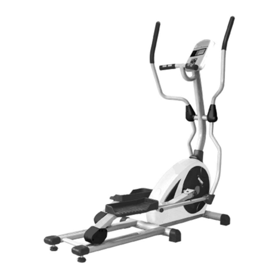
- Page 1 TROJAN X - C I T E 4 5 0 ® MY SPACE MY TIME E L L I P T I C A L T R A I N E R ELLIPTICAL TRAINER CARE INSTRUCTIONS AND ASSEMBLY MANUAL CAUTION...
-
Page 2: Table Of Contents
PRE ASSEMBLY CHECK LIST HARDWARE LIST ASSEMBLY STEPS COMPUTER FUNCTIONS TRANSPORT LUBRICATION FITNESS TIPS AND TECHNIqUES CONDITIONING GUIDELINES 10. WARM-UP AND COOL-DOWN 11. FREqUENTLY ASKED qUESTIONS 12. PARTS LIST 13. EXPLODED DRAWING 14. TROJAN 1 YEAR LIMITED WARRANTY 15. TROJAN REPAIRS PROCEDURE... -
Page 3: Safety Instructions
1. SAFETY INSTRUCTIONS WARNING : To reduce the risk of serious injury, read the following safety instruction before using the TROJAN X-CITE 450 ELLIPTICAL. 1. Use the TROJAN X-CITE 450 ELLIPTICAL only on a level surface. 2. Keep children and pets away from this equipment at all times. -
Page 4: Pre Assembly Check List
2. PRE ASSEMBLY CHECK LIST Thank you for choosing the TROJAN X-CITE 450 ELLIPTICAL. We take great pride in producing this quality product and hope it will provide many hours of quality exercise to make you feel better, look better and enjoy life to its fullest. -
Page 5: Hardware List
3. HARDWARE LIST NOTE : The described parts are all you need to assemble this machine. Before starting assembly, please check the hardware packing to make sure they are included. SD-800-5... -
Page 6: Assembly Steps
4. ASSEMBLY STEPS STEP 01 • Attach the Front Stabiliser (2) onto the Main Frame (1) with the Carriage Screw (4), Cap Nuts (6) and Arc Washers (5) STEP 02 • Insert the Aluminium Rails (52 & 53) into the Main Frame (1) and secure them with Carriage Bolts (50), Arc Washers (5) and Cap Nuts (6) STEP 03... - Page 7 ASSEMBLY STEPS STEP 04 • Slip the Cover (71) on the Upright Tube (72) • Connect the Monitor Cable (69) to the Sensor Wire (70) • Attach the Upright Post (72) onto the Main Frame (1) with Washers (26) and Screws (30) CAUTION: Ensure that cables are not damaged during assembly or when tightening screws.
- Page 8 ASSEMBLY STEPS STEP 07 • Place the Left Protecting Covers (104 & 105) on the joint of the Handle Bar and Sleeve. Use Screw (68) and Screw (82) to fasten. Repeat on the right side • Place the Left Protecting Covers (106 & 107) on the joint of Sleeve and Pedal Tube. Fasten using Screw (68) and Screw (82).
-
Page 9: Computer Functions
5. COMPUTER FUNCTIONS FUNCTIONS No preset target.Time will count up from 00:00 to 99:59 (maximum) Count up where each increment is 1 second. TIME If training with a preset Time. Time will count down from preset time to Count down 00:00.Each preset increment or decrement is 1 minute between 1:00 to 99:00 minutes. - Page 10 COMPUTER FUNCTIONS OPERATING INSTRUCTION Power on, Connect the adaptor to the rear of the unit to provide power to the computer. The LCD screen will display all segments and sound a long beep while showing the wheel diameter (78”) for 2 seconds (drawing 1). drawing 1 PROGRAMMING MODE 1.
- Page 11 COMPUTER FUNCTIONS 1.5 Press RESET button to return to training mode selection on the main menu. Program selections are MANUAL, PROGRAM, H.R.C. (Heart Rate Control), USER,WATT. Press UP and DOWN to select the program you want and press START for QUICK START in Manual mode. (drawing 7-10) drawing 7 drawing 8 drawing 9...
- Page 12 COMPUTER FUNCTIONS H.R.C. MODE (HEART RATE CONTROL) After entering H.R.C. mode, press the UP and DOWN button to select a different target from 55%, 75%, 90% and TARGET. Press MODE to confirm. (drawing 13) drawing 13 Note: 55% - Fat Burning Zone. (Exercise at this level for a minimum of 30 minutes at a time) 75% - Cardio Vascular Zone;...
-
Page 13: Transport
6. TRANSPORT The elliptical is equipped with two transport wheels which are engaged when the rear of the elliptical is lifted. 7. LUBRICATION 1. Pour 2ml of the lubricant onto the middle of the Rail. You must apply lubricant every three months (depending on how often the item is used). -
Page 14: Fitness Tips And Techniques
8. FITNESS TIPS AND TECHNIQUES AEROBIC EXERCISE Aerobic exercise is any sustained activity that sends oxygen to your muscles via your heart and lungs. Aerobic exercise improves the fitness of your lungs and heart - your body’s most important muscle. Aerobic exercise fitness is promoted by any activity that uses your large muscles -arms, legs, or buttock, for example. -
Page 15: Conditioning Guidelines
9. CONDITIONING GUIDELINES How you begin your exercise program depends on your physical condition. If you have been inactive for several years, or are severely overweight, you must start slowly and increase your time on the equipment; a few minutes per workout. Initially, you may be able to exercise only for a few minutes in your target zone, however, your aerobic fitness will improve over the next six to eight weeks. -
Page 16: Warm-Up And Cool-Down
10. WARM-UP AND COOL-DOWN WORKOUT GUIDELINES Each workout should include the following three parts: A warm-up, consisting of 5 to 10 minutes of stretching and light exercise. A proper warm-up increases your body temperature, heart rate, and circulation in preparation for exercise. Training zone exercise, consisting of 20 to 30 minutes of exercising with your heart rate in your training zone. -
Page 17: Frequently Asked Questions
11. FREQUENTLY ASKED QUESTIONS Q1. My elliptical does not move as easily as indicated in manual 1. Ensure you have placed the stabilizer with the wheels in the front of the unit. Q2. My consol does not work? 1. Make sure you have connected it correctly, the power source is connected and on 2. -
Page 18: Parts List
12. PARTS LIST 1. MAIN FRAME 2. FRONT STABILIZER 3. RAIL TUBE 4. HANDLEBAR 5. HANDLEBAR POST 6. COMPUTER 7. STEEVE 8. PEDAL ARM 9. PEDAL (L/R) 10. LEFT PROTECT COVER 11. RIGHT PROTECT COVER 12. LEFT PROTECT COVER 13. RIGHT PROTECT COVER. 14. -
Page 19: Exploded Drawing
13. EXPLODED DRAWING SD-800-19... - Page 20 EXPLODED DRAWING SD-800-20...
-
Page 21: Trojan 1 Year Limited Warranty
14. TROJAN 1 YEAR LIMITED WARRANTY Masstores (Pty)Ltd (“the Supplier”) hereby provides a limited warranty to the original purchaser of this product (“the Consumer”) that this product will be free of manufacturing defects in materials and workmanship which under normal, personal, family or household use (commercial use expressly excluded) manifest themselves within the following... - Page 22 The Consumer does not need to return the product to the store. The Consumer shall phone the Trojan hotline on 0861 Trojan (0861 876 526) and the Supplier’s authorized agent will at its discretion either repair the item at the Consumer’s residence or collect and repair the item at their premises.
-
Page 23: Trojan Repairs Procedure
15. TROJAN REPAIRS PROCEDURE 1. Procedure for repairs Should you experience any faults or breakdowns on your Trojan equipment, please adhere to the following procedure to have the fault rectified speedily and professionally. • Do not return the product to the store* Call 0861 Trojan (0861 876526) to log the faulty product (under warranty or out of warranty) •...
Need help?
Do you have a question about the X-CITE 450 and is the answer not in the manual?
Questions and answers