
Related Manuals for EverHot 271 SERIES


Summary of Contents for EverHot 271 SERIES
-
Page 1: Installation Instructions
Owner’s Guide Installation Instructions Continuous Flow Gas Water Heater 271, 275 Series This water heater must be installed and serviced by a qualified person. Please leave this guide with the householder. - Page 2 This water heater may be protected by one or more patents or registered designs in the name of Rheem Australia Pty Ltd or Paloma Co., Ltd. Rheem Australia Pty Ltd is the supplier of the Everhot range of continuous flow gas water heaters, manufactured by Paloma Co., Ltd., a world leader in water heater technology and manufacture.
-
Page 3: Table Of Contents
CONTENTS HOUSEHOLDER - We recommend you read pages 4 to 25. The other pages are intended for the installer but may be of interest. About Your Water Heater ......................4 Temperature Control ......................... 11 Water Supplies........................... 22 Save A Service Call ........................ -
Page 4: About Your Water Heater
Solar heated water can reach temperatures up to 75°C for an Everhot solar direct or indirect pumped system and possibly higher for some other models of solar water heaters. The in-series gas booster operates automatically. - Page 5 We recommend and it may be required by regulations that an approved temperature limiting device be fitted into the hot water piping to the bathroom and ensuite when a 271 series water heater is installed. This will keep the water temperature below 50°C at the bathroom and ensuite. The risk of scald injury will be reduced and if no controllers are installed and the preset outlet temperature setting has not been adjusted below 55°C or if a Kitchen controller is installed, still allow hotter water to the kitchen and laundry.
- Page 6 Warning: For continued safety of this water heater it must be installed, operated and maintained in accordance with the Owner’s Guide and Installation Instructions. The Everhot warranty may not cover faults if relief valves or other safety devices are tampered with or if the installation is not in accordance with these instructions.
- Page 7 ABOUT YOUR WATER HEATER PRECAUTIONS Where damage to property can occur in the event of the water heater leaking, the water heater must be installed over a safe tray. Construction, installation and draining of a safe tray must comply with AS/NZS 3500.4 and all local codes and regulatory authority requirements.
- Page 8 ABOUT YOUR WATER HEATER TO TURN OFF THE WATER HEATER If it is necessary to turn off the water heater: • Turn off the controllers(s) (if fitted) by pressing the on / off button. The light in the on / off button will go out and the priority light, if it is on, will go out. •...
- Page 9 The frost protection system will be rendered inoperable if electrical power is not available at the water heater. Damage caused by freezing due to the unavailability of power at the water heater is not covered by the Everhot warranty (refer to “Terms of the Everhot Warranty”...
- Page 10 Warning: Temperature controllers must not be fitted to this water heater if it is installed as an in-series gas booster (271 series) with a solar water heater system or if a Water Star water heater is installed, because water at a temperature much higher than the controller setting can be delivered. If a solar or Water Star water heater is installed to an existing water heater installation, then all controllers must be disconnected and removed.
-
Page 11: Temperature Control
Warning: Temperature controllers must not be fitted to this water heater if it is installed as an in-series gas booster (271 series) with a solar water heater system or if a Water Star water heater is installed, because water at a temperature much higher than the controller setting can be delivered. If a solar or Water Star water heater is installed to an existing water heater installation, then all controllers must be disconnected and removed. - Page 12 TEMPERATURE CONTROL CONTROLLER FUNCTIONS If one or more controllers are installed, at least one must be on for the water heater to operate. If all controllers are off, the water heater will only deliver cold water. on / off button – This button must be pressed once to turn on the controller.
- Page 13 TEMPERATURE CONTROL CONTROLLER priority light in use light display panel button water volume symbol down button water volume operating light on / off operating light water volume button on / off controller type button K = Kitchen B1 = Bathroom1 B2 = Bathroom2 Note: water volume button, water volume operating light and water volume symbol are on the Kitchen controller only.
- Page 14 5. On a building fitted with a temperature limiting device such as a tempering valve and where a 271 series water heater is installed without a separate untempered hot water line to the kitchen, laundry or other non- ablution area, although the Kitchen controller will be able to display temperatures above 50°C and the water...
- Page 15 • The temperature adjustment is made by pressing the up ( ) button or down ( ) button. • The maximum temperature setting for the controllers are: Kitchen Bathroom 271 series 60°C 50°C 275 series 48°C 48°C Each press of the up ( ) button will increase the temperature setting by one increment.
- Page 16 The Kitchen controller allows the user to select the temperature setting for the hot water to be used in the kitchen and laundry. It has a minimum temperature setting of 37°C and a maximum temperature setting of: • 271 series 60°C •...
- Page 17 The on / off operating light and the priority light will both glow. °C The Kitchen controller temperature setting will be displayed. This is the lower of the previous setting and: 271 series 50°C c h e c k h o t w a t e r water...
- Page 18 The Bathroom controller(s) allows the user to select the temperature setting for the hot water to be used in the bathroom. They have a minimum temperature setting of 37°C and a maximum temperature setting of: • 271 series 50°C •...
- Page 19 TEMPERATURE CONTROL To operate a Bathroom controller: Turn off the Kitchen controller If a temperature setting is displayed and the priority light is not glowing, it is advised to turn off the Kitchen controller. Refer to the notes on the Bathroom controllers on page 18.
- Page 20 TEMPERATURE CONTROL WATER VOLUME FUNCTION The water volume function is designed to warn, by a beeping sound, that a certain volume of water has been delivered from the water heater. It does not stop either the flow of or the heating of water. This function is particularly useful if a bath is being filled, or measuring the water consumed by the use of a shower.
- Page 21 TEMPERATURE CONTROL Turn off the alarm priority in us e Press the water volume button to turn off the alarm. The water volume operating light goes out and 0 x10l is °C displayed momentarily on the controller. The temperature setting of the controller with priority is then displayed.
-
Page 22: Water Supplies
In a corrosive water supply, the water can attack copper parts and cause them to fail. Where the saturation index is less than –1.0, the water is very corrosive and the Everhot warranty does not apply to a copper heat exchanger in a continuous flow water heater. -
Page 23: Save A Service Call
Check the items below before making a service call. You will be charged for attending to any condition or fault, which is not related to manufacture or failure of a part (refer to “Terms of the Everhot Warranty” page 55). - Page 24 • Collector area is too small For most installations, the number of solar collectors recommended in Everhot literature has been proven to provide the required solar energy to meet the average family needs. However, in some circumstances, it may be necessary to install an additional solar collector.
- Page 25 SAVE A SERVICE CALL CLOUDS OF WHITE ‘VAPOUR’ FROM THE FLUE TERMINAL During the heating cycle, it is not unusual to see water vapour clouds steaming from the flue terminal, particularly on cold days. This is normal operation of the water heater. PRESSURE RELIEF VALVE DISCHARGING A pressure relief valve is incorporated into the water heater controls.
-
Page 26: Installation – Water Heater
The 271 series of water heater may be installed as an in-series gas booster to a solar water heater. For information relating to the function and operation of the solar water heater, refer to the Owner’s Guide and Installation Instructions supplied with the solar water heater. - Page 27 INSTALLATION – WATER HEATER This water heater must be installed vertically upright with the water, gas and power connections on the underside, pointing toward the ground. The back of the water heater can be either against a wall or supported by a frame. The water heater must be secured to the wall or frame using either the screws provided or other mounting screws suitable for the application, two each at the top and bottom...
- Page 28 Damage to the water heater caused by freezing of the pipe work to or from the water heater is not covered under the Everhot warranty. Refer to AS/NZS 3500.4 for precautions to be taken for installations in frost prone areas. The water heater is not suitable for installation in areas where the ambient temperature falls below -20°C (including wind chill factor).
- Page 29 Gas Booster for a Solar Water Heater The temperature limiting device used with a 271 series in-series gas booster as part of a solar water heater installation must have the additional capability of receiving a hot water supply temperature of up to 99°C if the solar water heater does not have an over temperature protection system to limit the water to no greater than 90°C.
- Page 30 INSTALLATION – WATER HEATER Where a temperature limiting device is installed adjacent to the in-series gas booster, the cold water line to the temperature limiting device can be branched off the cold water line either before or after the isolation valve and pressure limiting valve to the solar storage tank, but it MUST BE before the non return valve prior to an open circuit direct system.
- Page 31 INSTALLATION – WATER HEATER CIRCULATED HOT WATER FLOW AND RETURN SYSTEM An Everhot 271 series continuous flow water heater can be installed as part of a circulated hot water flow and return system in a building. Notes: the preset outlet temperature setting of the water heater must be set to at least 60°C.
- Page 32 INSTALLATION – WATER HEATER from solar storage tank Circulated Hot Water Flow and Return In-series Gas Booster as part of a Solar Water Heater Installation REDUCING HEAT LOSSES The hot water line from the water heater and the pipe work between the solar storage tank, if one is installed, and the in-series gas booster must be insulated in accordance with the requirements of AS/NZS 3500.4.
- Page 33 INSTALLATION – WATER HEATER WATER TEMPERATURE DIAGRAMS 271 Series - Kitchen and Bathroom Controllers 275 Series – Kitchen and Bathroom Controllers 271 Series - Kitchen Controller Only 275 Series - Kitchen Controller Only 271 Series - Bathroom Controllers Only 275 Series - Bathroom Controllers Only...
- Page 34 INSTALLATION – WATER HEATER DIMENSIONS AND TECHNICAL DATA 271 026 Model 275 026 Rated delivery litres / min (@ 40°C rise) Recovery litres / min (@ 25°C rise) Mass Empty Hourly Gas Gas Details Test Point Gas Pressure (kPa) Min. Gas Pressure Max.
- Page 35 INSTALLATION – WATER HEATER DIMENSIONS – CONTROLLERS Kitchen Controller Bathroom Controller...
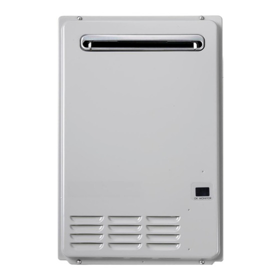
- Page 36 INSTALLATION – WATER HEATER TYPICAL INSTALLATION – OUTDOOR LOCATION...
-
Page 37: Connections – Plumbing
• 271 series in-series gas boosters with the following or a later suffix letter after the model number on the rating label of the water heater do not need to be installed with a solar bypass valve: 026 models •... - Page 38 Warning: Always isolate the water heater before pressure testing the gas supply system. Disconnect the water heater after the isolation valve to prevent the risk of serious damage to the gas control. The Everhot warranty does not cover damage of any nature resulting from failure to observe this precaution. Refer to...
-
Page 39: Connections – Electrical
Warning: Temperature controllers must not be fitted to this water heater if it is installed as an in-series gas booster (271 series) with a solar water heater system or if a Water Star water heater is installed, because water at a temperature much higher than the controller setting can be delivered. If a solar or Water Star water heater is installed to an existing water heater installation, then all controllers must be disconnected and removed. -
Page 40: Installation – Controllers
Warning: Temperature controllers must not be fitted to this water heater if it is installed as an in-series gas booster (271 series) with a solar water heater system or if a Water Star water heater is installed, because water at a temperature much higher than the controller setting can be delivered. If a solar or Water Star water heater is installed to an existing water heater installation, then all controllers must be disconnected and removed. - Page 41 KITCHEN CONTROLLER The Kitchen controller (PN 299900, including cable) is to be installed in the kitchen or laundry only. It has a minimum temperature setting of 37°C and a maximum temperature setting of: • 271 series 60°C • 275 series 48°C...
- Page 42 INSTALLATION – CONTROLLERS controller suitable wall anchors wall penetration cable projections terminal screws screws base plate controller screw Kitchen Controller Installation Concealed Cable If it is necessary to have an exposed wiring installation, follow this procedure omitting Steps 1 and 4, and make an opening in the thin section in the underside of the controller to accommodate the cable (as shown in the diagram), prior to Step 6.
- Page 43 If two Bathroom controllers are to be installed, one must be a Bathroom1 controller and the other must be a Bathroom2 controller (PN 299902, including cable). They have a minimum temperature setting of 37°C and a maximum temperature setting of: • 271 series 50°C • 275 series 48°C...
- Page 44 INSTALLATION – CONTROLLERS Wiring installation: Penetrate the wall with a 30-35 mm hole at the controller location. Install the supplied cable between the location of the controller and the water heater. Remove the base plate from the controller. Peel off one side of the adhesive paper from the foam packing and adhere to the back face of the base plate.
- Page 45 INSTALLATION – CONTROLLERS CONNECTING THE CONTROLLER(S) TO THE WATER HEATER To connect the controller(s) to the water heater: water heater Ensure the electrical supply to the water heater is switched off. Unscrew and gently remove the electrical cover from the underside of the water heater.
-
Page 46: Commissioning
COMMISSIONING All water heaters are tested and adjusted before dispatch from the factory, however further adjustments may become necessary because of local conditions. TO TURN ON THE WATER HEATER • Open all of the hot taps in the house (don’t forget the shower). •... - Page 47 COMMISSIONING Gas Inlet Test Point Pressure To check the gas inlet pressure: Close any hot taps and ensure the burners are not operating. Close the gas isolation valve at the gas inlet to the water heater. Locate the gas inlet test point on the gas connection to the water heater.
- Page 48 Warning: The removal of the front panel will expose 240 volt wiring. Take care not to touch wiring terminals. Note: If a 271 series model is installed as an in-series gas booster to a solar water heater, then during this procedure the temperature of the water entering the in-series gas booster must be below 58°C. Otherwise the gas burners will not ignite and the operational gas pressures cannot be measured.
- Page 49 COMMISSIONING Notes: • If the burners extinguish and / or an error code starts to flash on the LED display: release the MIN and adjuster buttons close the hot tap clear the error code (refer to “Clearing Error Code” on page 49) recommence the procedure from Step 8.
- Page 50 COMMISSIONING PRESET OUTLET TEMPERATURE SETTING The factory preset outlet temperature setting of the water heater is: • 271 series (pre 2007 manufacture date) 50°C • 271 series (from 2007 manufacture date) 60°C • 275 series 48°C If a temperature controller is connected to the water heater, this will override the preset outlet temperature...
- Page 51 COMMISSIONING TO CHECK OR ADJUST THE PRESET OUTLET TEMPERATURE SETTING The temperature settings will be displayed on the LED display. The preset outlet temperature settings are: • 271 series 40°C, 43°C, 50°C, 55°C, 60°C, 70°C • 275 series 40°C, 43°C, 48°C It is necessary to have the electrical supply to the water heater switched on during stages of checking or adjusting the preset outlet temperature setting procedure.
-
Page 52: Draining The Water Heater
• Damage caused by freezing due to the unavailability of power at the water heater is not covered by the Everhot warranty (refer to “Terms of the Everhot Warranty” on page 55). • If the power has been switched off to the water heater and there is a risk of freezing, then it is necessary to drain the water heater (refer to “Draining the Water Heater”... - Page 53 This page is intentionally blank.
- Page 54 This page is intentionally blank.
-
Page 55: Warranty
2.8 If you require a call out and we find that the fault is not covered by the Everhot warranty, you are responsible for our standard call out charge. If you wish to have the relevant component repaired or replaced by Rheem, that service will be at your cost. - Page 56 6.2 The Everhot warranty (set out above) is in addition to any rights and remedies that you may have under the Australian Consumer Law.
Need help?
Do you have a question about the 271 SERIES and is the answer not in the manual?
Questions and answers