Table of Contents
Advertisement
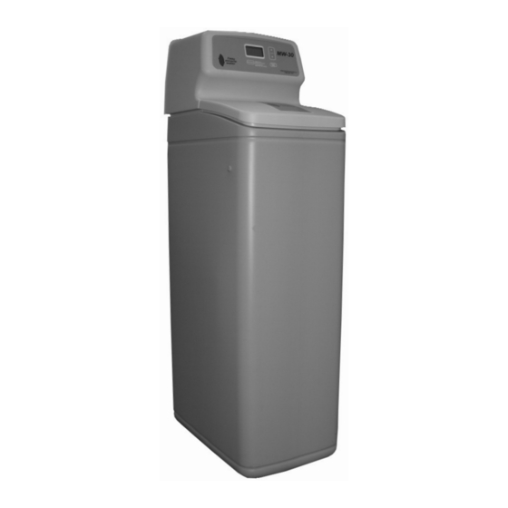
Model MW-30
How to maintain and operate
your Demand Controlled
Water Softener
DO NOT RETURN TO STORE
If you have questions or concerns when
installing, operating or maintaining your
softener, visit www.leaumiraclewater.ca
or call our toll free number:
1-800-356-7851
System tested and certified by NSF International
against NSF/ANSI Standard 44
for hardness reduction and efficiency,
and certified to NSF/ANSI Standard 372.
System tested and certified by the Water Quality
Association against CSA B483.1.
7337539 (Rev. A 1/2/13)
Advertisement
Table of Contents

Related Manuals for l'eau miracle water MW-30

Summary of Contents for l'eau miracle water MW-30
- Page 1 Model MW-30 How to maintain and operate your Demand Controlled Water Softener DO NOT RETURN TO STORE If you have questions or concerns when installing, operating or maintaining your softener, visit www.leaumiraclewater.ca or call our toll free number: 1-800-356-7851 System tested and certified by NSF International...
-
Page 2: Table Of Contents
Table of Contents Unpacking and Inspection ............. . .3 Softener Dimensions . -
Page 3: Unpacking And Inspection
Unpacking and Inspection The parts required to assemble and install the unit are included in a parts bag. Thoroughly check the unit for possible shipping damage and parts loss. Also inspect and note any damage to the shipping carton. Remove and discard (RECYCLE) all packing materials. To avoid loss of small parts, we suggest you keep the small parts in the parts bag until you are ready to use them. -
Page 4: Softener Dimensions
Softener Dimensions MODEL NOMINAL RESIN TANK SIZE MW-30 9” Dia. x 35” 37” 33” 42” Salt Storage Capacity MW-30 - 150 lbs. Wiring Schematic Miracle Water Installation & Operation Manual... -
Page 5: Miscellaneous Service Information
Miscellaneous Service Information DESIGN SPECIFICATION MW-30 FILL CYCLE FLOW .3 gpm BRINE CYCLE 2 FLOW .22 gpm 2 FLOW BRINE RINSE CYCLE .15 gpm BACKWASH CYCLE (MAX.) 2 FLOW 2.0 gpm FAST RINSE CYCLE (MAX.) 2 FLOW 2.0 gpm gallon per minute flow to brine tank... -
Page 6: Safety Guides
Safety Guides Follow the installation instructions carefully. (Failure to install the unit properly voids the war- ranty.) Before you begin installation, read this entire manual. Then, obtain all the materials and tools you will need to make the installation. Check local plumbing and electrical codes. The installation must conform to them. Use only lead-free solder and flux for all sweat-solder connections, as required by state and fed- eral codes. - Page 7 crust on cooking utensils, appliances, and plumbing fixtures. Even the tastes of foods are affect- ed. A water softener removes the hardness minerals to eliminate these problems, and others. Sodium Information: Water softeners using sodium chloride (salt) for regeneration and add sodium to the water.
-
Page 8: Assembly
Assembly 1. Miracle Water models are factory assembled. During installation, remove the Salt Hole Cover. Set aside to prevent damage. Check the brinewell to be sure it is secured and vertical (see Figure 1). Slide Faceplate Cover forward to expose back valve assembly. 2. -
Page 9: Planning Installation
Planning Installation Inlet - Outlet Plumbing Options • ALWAYS INSTALL either a single bypass valve (included) or a 3 valve bypass system (not included). Bypass valves allow you to turn off water to the softener for repairs if needed, but still have water in house pipes. -
Page 10: Other Requirements
Other Requirements • A 120V-60Hz, grounded electrical outlet (continuously ‘‘live’’) is needed nearby the unit. • A drain is needed for regeneration discharge water. A floor drain, close to the unit, is preferred. A laundry tub, standpipe, etc., are other drain options. Tools and Materials You May Need •... -
Page 11: Select Installation Location
*VALVE DRAIN OPTIONS: Flexible drain hose is not allowed in all localities (check your plumb- ing codes). For a rigid valve drain run, cut the barbed section off the drain fitting for access to the 1/4” pipe threads. Then plumb a rigid drain as needed (see Figure 4). Select Installation Location Consider all of the following when selecting an installation location for the unit. -
Page 12: Installation
Installation Step 1. Turn Off Water Supply 1. Close the main water supply valve, near the well pump or water meter. 2. Shut off the electric or fuel supply to the water heater. 3. Open all faucets to drain all water from the house pipes. Step 2. -
Page 13: Step 3. Assemble Inlet And Outlet Plumbing
Step 3. Assemble Inlet and Outlet Plumbing Measure, cut, and loosely assemble pipe and fittings from the main water pipe to the inlet and out- let ports of the valve. Be sure hard water supply pipe goes to the valve inlet side. NOTE: Inlet and outlet are marked on the valve. -
Page 14: Step 6. Install Valve Drain Hose
Step 6. Install Valve Drain Hose NOTE: See valve drain options on page 11. 1. Connect a length of 3/8” or 7/16” I.D. hose (check codes) to the valve drain elbow, on the con- troller, see Figure 4. Use a hose clamp to hold the hose in place. Route the hose out through the notch in the Faceplate Cover. -
Page 15: Step 9. Add Water And Salt To The Salt Storage Tank
3. Fully open the main water supply valve. Observe steady flow from the opened faucets, with no air bubbles. 4. EXACTLY as follows, place bypass valve(s) in “service”. a. SINGLE BYPASS VALVE: SLOWLY, move the valve stem toward “service”, pausing several times to allow the unit to pressurize slowly. -
Page 16: Step 11. Program The Controller
Step 11. Program the Controller 1. Install the salt hole and faceplate covers. 2. Complete the Programming Steps on Pages 17, 18 and 19. Step 12. Sanitizing the Softener Care is taken at the factory to keep your unit clean and sanitary. Materials used to make the unit will not infect or contaminate your water supply, and will not cause bacteria to form or grow. -
Page 17: Programming The Faceplate Timer
Programming the Faceplate Timer Display UP button TONIGHT (Press) SELECT RECHARGE NOW (Hold for 3 seconds) www.leaumiraclewater.ca MENU CE SOIR (Appuyer) 1- -800- -356-7851 MAINTENANT (Tenir appuyer) RECHARGE button SELECT/MENU button DOWN button Figure 12 If you have questions about installation, programming, operating and routine maintenance... call 1-800-356-7851 When the transformer is plugged into the electrical outlet, a model code and a test number (exam- ple: J2.0), begins to flash in the faceplate display. -
Page 18: Step 2. Set Water Hardness Number
Step 2. Set Water Hardness Number 1. Press the (Select/Menu) button once to display a flashing 25 and HARDNESS. SELECT MENU 2. Press the UP or DOWN q buttons to set your water hardness number. NOTE: Be sure to enter the grains per gallon (gpg) hardness of your water supply on page 4, for future reference. -
Page 19: Step 4. Set Salt Efficiency
Step 4. Set Salt Efficiency When this feature is ON, the unit will operate at salt efficiencies of 4000 grains of hardness per pound of salt or higher. (May recharge more often using smaller salt dosage and less water). 1. Press and hold the (Select/Menu) button until the following screen is displayed. -
Page 20: Customizing Features/Options
Customizing Features/Options Recharge Now If you have guests, or other times when more water than usual is used, you could begin to run out of conditioned water. If the unit is not scheduled to regenerate for another day or two, you could get hard water until then. -
Page 21: Adjustable Backwash
Customizing Features/Options Adjustable Backwash If your incoming water supply has higher sediments or iron, a longer Backwash and/or Fast Rinse time may help in keeping the unit cleaner. 1. Press and hold the (Select/Menu) button until the following screen is displayed. SELECT MENU Once in this display, press the... -
Page 22: Routine Maintenance
Routine Maintenance Refilling With Salt Remove the Salt Storage Tank Front Cover and check the salt storage level frequently. If the con- ditioner uses all the salt before you refill it, you will get hard water. Until you have established a refilling routine, check the salt every two or three weeks. -
Page 23: Cleaning The Nozzle And Venturi
Cleaning the Nozzle and Venturi A clean nozzle and venturi (see Figure 14) is a must for the conditioner to work properly. This small unit creates the suction to move brine from the brine tank, into the resin tank. If it should become plugged with sand, silt, dirt, etc., the conditioner will not work, and you will get hard water. -
Page 24: Protect The Water Softener From Freezing
Protect the Water Softener from Freezing If the softener is installed where it could freeze (summer cabin, lake home, etc.), you must drain all water from it to stop possible freeze damage. To drain the softener: 1. Close the shut-off valve on the house main water pipe, near the water meter or pressure tank. 2. -
Page 25: Troubleshooting Guide
Troubleshooting Guide Tools Needed for Most Repairs: 5/16 Hex Driver, Phillips Screwdriver, Needle-nose Pliers PROBLEM CAUSE SOLUTION REPAIR KIT(S) NEEDED No Soft Water 1. No Salt in the storage tank a. Add salt (see page 22) None b. Use Recharge Now feature (page 20) No Soft Water Timer 1. -
Page 26: Automatic Electronic Diagnostics
Automatic Electronic Diagnostics The faceplate has a self-diagnostic function for the electrical system (except input power and/or water meter). The faceplate monitors electronic components and circuits for correct operation. If a malfunction occurs, an error code appears in the faceplate display. The troubleshooting chart on page 26 shows the error codes that could appear, and the possible defects for each code. -
Page 27: Resetting To Factory Defaults
NOTE: Be sure water is in contact with the salt, and not separated by a salt bridge... see page 23. 5. While in this diagnostic screen, the following information is available and may be beneficial for various reasons. This information is retained by the computer from the first time electrical power is applied to the face plate. -
Page 28: Manual Advance Regeneration Check
Manual Advance Regeneration Check This check verifies proper operation of the valve motor, brine tank fill, brine draw, regeneration flow rates, and other controller functions. Always make the initial checks, and the manual initiated diag- nostics. NOTE: The faceplate display must show a steady time (not flashing). If an error code shows, first press the (Select/Menu) button to enter the diagnostic display. -
Page 29: Softener Components
Softener Components Bypass Valve Power Supply Kit P/N 7129871 P/N 7238426 Motor Switch Kit P/N 7285910 Valve Kit P/N 7238557 Motor Plate Electronic Control Board P/N 7231385 P/N 7327534 Cam & Gear Kit P/N 7254252 Resin Tank Assembly P/N 7269273 Float Kit P/N 7238476 Valve Cover... -
Page 30: Warranty
Warranty MIRACLE WATER RESIDENTIAL WARRANTY Miracle Water guarantees to the original owner, that: For a period of ten (10) years from the date of purchase, the salt storage tank and fiberglass mineral tank will not rust, cor- rode, leak, burst, or in any other manner, fail to perform their proper functions; and that For a period of one (1) year from the date of purchase, all other parts will be free of defects in material and workmanship and will perform their normal functions.
Need help?
Do you have a question about the MW-30 and is the answer not in the manual?
Questions and answers