Advertisement
Quick Links
Advertisement

Related Manuals for Extreme Flight 110" YAK-54 V2


Summary of Contents for Extreme Flight 110" YAK-54 V2
- Page 1 110" YAK-54 V2 Assembly Manual Copyright Extreme Flight 2015...
- Page 2 It is beyond our control to monitor the finished aircraft you produce. Extreme Flight RC will in no way accept or assume responsibility or liability for damages resulting from the use of this user assembled product.
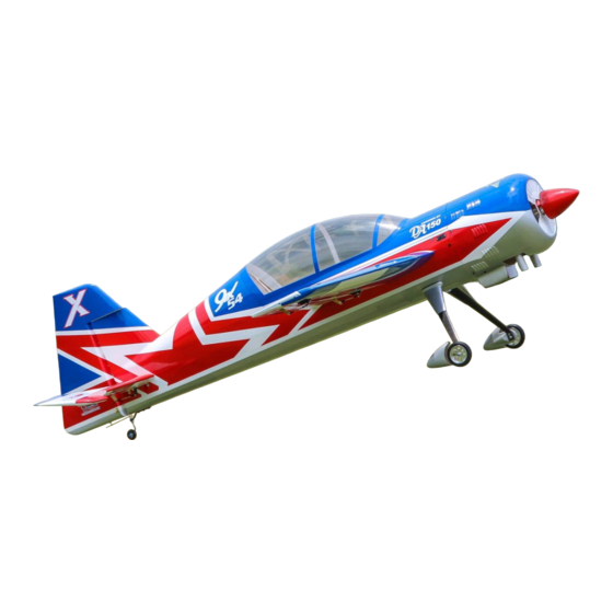
- Page 3 We are very proud of the end result of our labor and wish you great success with the assembly and flying of your Extreme Flight RC 110 inch Yak 54!
- Page 4 Masking or painters tape. Hobby knife with #11 blades. Fresh Thin and medium CA. We highly recommend Mercury M5T thin and M100XF medium formulas as well as the Mercury glue tips. Fresh 30 minute epoxy. Mercury Adhesives Epoxies have worked very well for Blue and Red Loctite thread locking compound.
- Page 5 Your flying experience will be greatly enhanced once your plane is properly dialed in. 7. Extreme Flight now has their own Vimeo channel and we highly recommend viewing the assembly videos on this resource. There are many assembly videos providing extreme detail on certain aspects of the assembly of this very model and performed by Jeff Williams.
- Page 6 Here are the included kit components: Hardware packages...
-
Page 7: Let's Begin
Let's begin: 1. Locate the wing panels/ailerons and horizontal stabilizers/elevators and associatedhardware bags. We will begin by hinging all of these at one time. I suggest you scuff/roughthe surface of the hinges, they are slick from the manufacturing process and the glue willadhere better to a non-slick surface. Using 100-150 grit sandpaper works well to do this, be sure you don't sand the barbs off the hinge, you just want a little scuffing on the hinge, do not sand at the pivot point. - Page 8 insert it until the pin is even with the hinge line. Be sure your hinge pivots freely and is perpendicular to the hinge line. Allow to dry, then mate to the appropriate surface (wing toaileron/horizontal stabilizer to elevator) and allow that to dry. Refer to figure 1 for the 3 clipped horizontal stabilizer hinges, all other hinges are normal length.
- Page 9 At this point you should have the both wings/horizontal stabilizer and ailerons/elevators hinged. Now check that each hinge moves freely, if not then work the hinge till it does move freely. If it is still binding, apply a very small drop of 3in1 oil to the pin only.
- Page 11 Figure 3. Now is the time to decide if you will run 2 or 3 aileron servos. If you are running servos that have at least 400oz inches of torque, two should be sufficient. We chose the MKS777HV for our ailerons. You can always add the middle aileron servo later if you find it necessary.
- Page 12 Figure 4. 5.25” inner aileron slot Figure 5. 7.5” outer aileron slot...
- Page 13 Remove the covering to expose ONLY the slots. Now take the control horns and trial fit them thru the base plate and then into the slots. Now use blue tape or other method to determine how much covering to remove from under the base plate to attain a base plate to wood joint.
- Page 14 4.Gather your aileron and elevator servos, all servo arms and hardware so we can install those items. I will discuss the elevator installation, but the ailerons install very similarly. I found it is easier to mount the servos without the servo arm attached, so install your elevator servo into the slot and secure with the manufacturers recommended screws.
- Page 15 Figure 8. Finish the remaining elevator and aileron servo pushrod installations, this will complete the wing/aileron and horizontal/elevator assemblies. 6. If you did not install the hinges into the vertical stabilizer in step 1, glue them in now and then mate the rudder to the vertical using the same methods as the wing/aileron.
- Page 16 install without the main landing gear installed. So locate your tailwheel parts bag. Figure 9 shows all the landing gear parts. Figure 9 Main landing gear cuffs spats Tailwheel assembly tailwheel hardware axles main tires See figure 10 for the parts layout of the tailwheel assembly.
- Page 17 Figure 10 wheel collars tailwheel wire tailwheel 3mm bolts/washers ball link tailwheel bracket tiller bolt housing/nut Begin assembly of the tailwheel by taking the bolt housing/nylon insert nut and installing the bolt into the tailwheel bracket and the nut. The nut goes onto the bottom, tighten use blue thread lock (which I will not abbreviate to BTL).
- Page 18 The factory already installed the blind nuts during their assembly, so just apply BTL and tighten. See figure 11 for a completed tailwheel assembly. Figure 11 9. There are two ways to install the main landing gear (MLG). You can either put the wheels/spats on first then bolt the MLG to the fuselage or bolt the MLG to the fuselage and then install the wheel/spats.
- Page 19 Figure 12 NOTE: the washers used on the axles have a slightly larger hole than the washers for the MLG, please differentiate this before proceeding. Now slide the spat onto the axle and over the hex head of the axle, then install the 3mm bolt/washer into the blind nut and tighten, use BTL.
- Page 20 where this large would be, once you are satisfied stick a marking device thru the wheel center and mark a spot. See figure 13 for aligning the spat. Figure 13 Now drill out that out and I suggest you begin with a small drill bit and progressing upwards till you get a 5/8”...
- Page 21 Align the tire within the spat, there should be no rubbing anywhere, once this is as desired then tighten the wheel collar and use BTL. Now install the remaining wheel collar and tighten using BTL. Repeat for the other side to complete the wheel/spat installation.
- Page 22 10. I found it easiest to lay the fuselage on its’ side to install the main landing gear (MLG). Locate the 4mm bolts/washers/nylon insert nuts and associated tools. I suggest you have these items nearby as the gear is so large it can be a handful to coordinate all of this.
- Page 23 Figure 16...
- Page 24 12. We will illustrate the DA120 with stock muffler option, but there are many power plant/muffler options you could use. The DA120 will require 1.75” standoffs, this will yield 1” of clearance between the back of the spinner and the front of the cowl. You could go down to ¾” but 1” is preferred.
- Page 25 Figure 18 13. Now install your throttle servo, we use the MKS1250. It mounts inside the motor box just behind the engine’s firewall in a precut mount. Locate your...
- Page 26 hardware package and thread the white ball link onto the threaded end of the pushrod. Now approximate where your pushrod should go thru the firewall and drill a 1/8” hole. You may need to bend the pushrod to fit around your unique engine standoff/installation, this is fine to do if needed.
- Page 27 Figure 21...
- Page 28 14. The cowling is already drilled and the mounts are in place, to install simply slide it onto the mounts and install the supplied 3mm bolts. However, with stock mufflers you will need to cut holes in the bottom of the cowl to accommodate the muffler outlets.
- Page 29 You will also need to cut exit air holes in the cowling. Follow your engine manufacturers recommendations, but rule of thumb is three times the inlet air area is how big your exit air area needs to be. Now you can install the front baffle plate. I first cut a center hole for the engines prop shaft, I simply followed a small circular pattern that was already formed into the baffle.
- Page 30 Figure 25...
- Page 31 Now you can glue the baffle into the front of the cowl using epoxy, welders adhesive or similar glues. I recommend sanding that portion of the baffle plate that will not be seen to allow better adhesion. There are two ways to hold the baffle plate in place with pressure.
- Page 32 15. Next mount your tank. We used the new Extreme Flight Flowmaster tank and Flowmaster fuel tubing. The tank is ready to install upon receipt of it, however I chose to install the small brass tubing on the inner pickup line, this defends against the clunk wrapping itself around to the front of the tank.
- Page 33 Figure 29 16. Now install the Extreme Flight fuel dot. I chose the forward switch location on the right side of the fuselage. You will need to cut a hole ¾” diameter and I located that in the center of that switch’s cutout. See figure 30 for the location I used.
- Page 34 Figure 30 Now cut the hole for the Extreme Flight fuel dot and install it using the screws with BTL. See figures 31 and 32 for my installation. Figure 31 Figure 32...
- Page 35 Now run all your fuel lines, the outlet nipple of the Flowmaster tank goes to the carburetor, the top elbow with the fuel line connected is your fuel/defuel line and it goes to the fuel dot, the remaining top elbow is your vent line. I recommend looping it around your tank then out the bottom of the airplane, typically we go out the bottom of the cowling.
- Page 36 range to the 150cc range and it would be impossible to write a manual to accommodate every scenario. Therefore, I recommend installing all your radio components, assembling the airplane and then put the rudder servo(s) in the middle tray and see how it balances. A good starting CG is the middle to aft section of the wing tube.
- Page 37 Lower control horn location for direct drive upper slots for pull pull If you have not installed your rudder control horns in earlier steps, do this now using the same process as the wings/ailerons. OK let’s proceed with the way to setup the pull pull system, which is the likely choice if using a DA120.
- Page 38 Figure 34 pushrods for direct drive 60mm length coated cable Ball links crimps rigging couplers The rudder pull pull system is started by gluing the included double rudder tray to the middle tray area if you are using standard size servos. The tray, as is, has one enlarged slot in case you wanted to use a larger case servo, then you would not use the optional double rudder tray.
- Page 39 Figure 35 It does not matter which end you begin, the servo or the control horn. Take one end of the cable and slide a crimp onto it then thread it thru the eye of the rigging coupler and leave about 4-5” of excess cable beyond the rigging coupler. NOTE: For a clean appearance I use heat shrink tubing and slide it over the crimp and coupler for a finished look.
- Page 40 Figure 36 Figure 37...
- Page 41 Figure 38 You may trim the excess cable, I left about 3/8”. Optionally, from the other end of the cable I slid a piece of heat shrink over the crimp area to protect from any fraying and to leave a clean appearance.Be sure you cross the cable as it runs thru the fuselage to the other hookup.
- Page 42 If you are doing the direct drive/push-pull option then locate the servo bay and remove the covering to expose location. Looking at Figure 39 you can see the servo bay is approximately 3” forward of the rudder hinge line. In that same figure 39 you can see how the controls horns are in very different locations to accommodate each rudder setup.
- Page 43 Figure 40 This completes the assembly of the model, please read the remaining sections and you will find some very useful information. Setup and flying: I installed my batteries and receiver in the rudder tray, but you can locate your batteries as needed if the rudder servo method in step 18 did not yield the desirable CG location.
- Page 44 The desired range is: Forward limit CG - front of wing tube Most desirable CG – Midpoint of wingtube to trailing edge of wing tube Aft limit CG – up to .5" behind the trailing edge of the wing tube One way to test your CG is to fly inverted and see if it climbs or descends.
- Page 45 Gear span from outer edge of cuff to other cuff = 30.5” Front of firewall to front of cowling = 7” Cowling inner diameter = 13.75” THANKS and we hope you enjoy your new Extreme Flight RC 110” Yak 54.
Need help?
Do you have a question about the 110" YAK-54 V2 and is the answer not in the manual?
Questions and answers