
Related Manuals for Gewiss ACTIVO GW 40 251

Summary of Contents for Gewiss ACTIVO GW 40 251
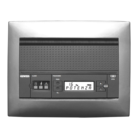
- Page 1 SERIE 40 CD IP40 Centralini EWISS CTIVO control systems EWISS CTIVO ALARM PROGRAMME OPEN PROG. MODE – TEL. 12 mod. 24 mod. GW 40 251 GW 40 256 GW 40 271 GW 40 276...
- Page 3 ATTENZIONE - IMPORTANTE Ci congratuliamo con Lei per la scelta di prodotti Gewiss. I prodotti Gewiss sono costruiti con attente cure dei dettagli impiegando solo materiali di qualità elevata. I prodotti Gewiss le garan- tiranno nel tempo prestazioni ottimali. Leggere attentamente le seguenti istruzioni in quanto forniscono importanti informazioni sulle modalità...
-
Page 4: Functions
In case of a breakdown or malfunctioning, please contact an authorized technician or GEWISS’ SAT helpdesk. GEWISS reserves the right, in its sole discretion, (at all times and without prior notice), to make any changes to its products that it deems necessary for technological or manufacturing purposes, or as an improvement in use or performance. -
Page 5: Table Of Contents
INDICE / INDEX pag./ page • GENERALITÀ PRODOTTO / GENERAL PRODUCT DESCRIPTION - Funzioni Functions ......................• ISTRUZIONE D’INSTALLAZIONE / INSTALLATION INSTRUCTIONS - Schemi di collegamento Wiring diagrams ....................- Morsettiera centralino Control system terminal block ................13 - Montaggio Fitting ....................... -
Page 6: Generalità Prodotto / General Product Description - Funzioni Functions
GENERALITÀ PRODOTTO GENERAL PRODUCT DESCRIPTION FUNZIONI FUNCTIONS ☞ SICUREZZA PREVENTIVA • Segnala attraverso indicazioni luminose, acustiche ed il display le anomalie di funzio- namento dell’impianto elettrico. • Previene le interruzioni dell’alimentazione segnalando il superamento della soglia preim- postata di energia e, se predisposta/programmata, interrompendo l’alimentazione al cari- co collegato alla linea non prioritaria. - Page 7 GENERALITÀ PRODOTTO GENERAL PRODUCT DESCRIPTION FUNZIONI FUNCTIONS ☞ PREVENTIVE SAFETY • Indicates functional faults of the electrical system through luminous and sound signals and a display. • Prevents power failures by warning that the preset power threshold has been passed and if equipped/programmed, cuts off the power supply to the load connected to the non-priority line.
-
Page 8: Istruzione D'installazione / Installation Instructions - Schemi Di Collegamento Wiring Diagrams
ISTRUZIONE D’INSTALLAZIONE INSTALLATION INSTRUCTIONS SCHEMA DI COLLEGAMENTO 12/24 MODULI - BASE WIRING DIAGRAM 12/24 MODULES - STANDARD Attenzione: prima di accedere al vano cablaggi sezionare Q.tà Q.ty Cavi l’impianto a monte del centralino. POS. Cables 12 m 24 m Warning: before accessing the wiring, always cut off the power 320 mm supply upstream of the control system. - Page 9 ISTRUZIONE D’INSTALLAZIONE INSTALLATION INSTRUCTIONS SCHEMA DI COLLEGAMENTO 12/24 MODULI WIRING DIAGRAM 12/24 MODULES con bobina di sgancio e combinatore telefonico with release coil and telephone dial Q.tà Q.ty Cavi Attenzione: prima di accedere al vano cablaggi sezionare POS. Cables 12 m 24 m l’impianto a monte del centralino.
- Page 10 ISTRUZIONE D’INSTALLAZIONE INSTALLATION INSTRUCTIONS SCHEMA DI COLLEGAMENTO 12/24 MODULI WIRING DIAGRAM 12/24 MODULES con bobina di sgancio e programmatore with release coil and programmer Attenzione: prima di accedere al vano cablaggi sezionare Q.tà Q.ty Cavi POS. Cables l’impianto a monte del centralino. 12 m 24 m 320 mm...
- Page 11 ISTRUZIONE D’INSTALLAZIONE INSTALLATION INSTRUCTIONS SCHEMA DI COLLEGAMENTO 12/24 MODULI WIRING DIAGRAM 12/24 MODULES con bobina di sgancio e differenziale ReStart / Autotest with release coil and ReStart / Autotest differential Q.tà Q.ty Cavi Attenzione: prima di accedere al vano cablaggi sezionare POS.
- Page 12 ISTRUZIONE D’INSTALLAZIONE INSTALLATION INSTRUCTIONS SCHEMA DI COLLEGAMENTO 12/24 MODULI WIRING DIAGRAM 12/24 MODULES LEGENDA / LEGEND A: Bobina di sgancio - (es. cod. GW 96 012 - si attiva con il superamento della soglia di prelievo programmata). B: Interruttore per carico non prioritario (es. cod. GW 90 047). A: Release coil - (e.g.
-
Page 13: Morsettiera Centralino Control System Terminal Block
ISTRUZIONE D’INSTALLAZIONE INSTALLATION INSTRUCTIONS MORSETTIERA CENTRALINO CONTROL SYSTEM TERMINAL BLOCK modulo elettronico electronic module 2 3 4 5 Relé 1 - Relay 1 NC (NC) Combinatore telefonico - Programmatore 1A - 125V~ Telephone dial - Programmer NA (NO) L’attivazione del combinatore telefonico avviene mediante il cambio di stato del contatto in uscita per 4 secondi. -
Page 14: Fitting
ø 10x1,5 TC 2,9x14 ø 10x1 Possibilità di installare su scatole da incasso preesistenti degli altri centralini GEWISS, 12 moduli da arredo e standard protetti. Utilizzare le rondelle (pos. 6) per compensare le diverse profondità di muratura della scatola. Verificare, dopo il montaggio, che il telaio non presenti deformazioni. - Page 15 ISTRUZIONE D’INSTALLAZIONE INSTALLATION INSTRUCTIONS MONTAGGIO CENTRALINO 12 MODULI FITTING CONTROL SYSTEM 12 MODULE POS. Q.tà TC 4x32 TC 3,5x16 ø 10x1,5 TC 2,9x14 ø 10x1...
- Page 16 ø 10x1,5 TC 2,9x14 ø 10x1 Possibilità di installare su scatole da incasso preesistenti degli altri centralini GEWISS, 24 moduli da arredo e standard protetti. Utilizzare le rondelle (pos. 6) per compensare le diverse profondità di muratura della scatola. Verificare, dopo il montaggio, che il telaio non presenti deformazioni.
- Page 17 ISTRUZIONE D’INSTALLAZIONE INSTALLATION INSTRUCTIONS MONTAGGIO CENTRALINO 24 MODULI FITTING CONTROL SYSTEM 24 MODULE POS. Q.tà TC 4x32 TC 3,5x16 ø 10x1,5 TC 2,9x14 ø 10x1...
- Page 18 ISTRUZIONE D’INSTALLAZIONE INSTALLATION INSTRUCTIONS MONTAGGIO CENTRALINO 12-24 MODULI FITTING CONTROL SYSTEM 12-24 MODULE È possibile aprire la portella tramite il tasto oppure tramite il pomello centrale. Open the flap by pressing the key or using the central knob...
-
Page 19: Disassembly
ISTRUZIONE D’INSTALLAZIONE INSTALLATION INSTRUCTIONS SMONTAGGIO CENTRALINO 12-24 MODULI DISASSEMBLY CONTROL SYSTEM 12-24 MODULE... -
Page 20: Istruzioni D'impiego Operating Instructions
ISTRUZIONI D’IMPIEGO OPERATING INSTRUCTIONS DESCRIZIONE COMANDI DESCRIPTION OF THE CONTROLS K w K w Allarme luminoso - Segnala la mancata erogazione di energia dell’ente distributore (pag. 40). Allarme luminoso - Segnala l’intervento della soglia di corrente di dispersione max superata. Allarme luminoso - Segnala l’avvenuto intervento delle apparecchiature modulari di protezione: Interruttori automatici (pag. - Page 21 ISTRUZIONI D’IMPIEGO OPERATING INSTRUCTIONS DESCRIZIONE COMANDI DESCRIPTION OF THE CONTROLS Warning light - Indicates Power failure condition (page 40). Warning light - Indicates cutting in of the max. leakage current exceeded threshold. Warning light - Indicates cut-in of the modular protection equipment: Automatic switches (page 42) - Exceeding of preset power value (page 45) - Test on the residual current device (page 54) - ReStart / Autotest Alarms (if available, see page 48).
-
Page 22: Visualizzazione Dei Parametri Dell'impianto
ISTRUZIONI D’IMPIEGO OPERATING INSTRUCTIONS VISUALIZZAZIONE DEI PARAMETRI DELL’IMPIANTO DISPLAY OF THE SYSTEM PARAMETERS Stato iniziale: orologio Starting mode: clock Premere il tasto per visualizzare il parametro succesivo. MODE Press the key to display the next parameter. MODE Potenza Power P P O O T T E E N N Z Z A A P P O O W W E E R R Premere il tasto per visualizzare il parametro succesivo. - Page 23 ISTRUZIONI D’IMPIEGO OPERATING INSTRUCTIONS VISUALIZZAZIONE DEI PARAMETRI DELL’IMPIANTO DISPLAY OF THE SYSTEM PARAMETERS Potenza media Average power P P O O T T E E N N Z Z A A M M E E D D I I A A A A V V E E R R A A G G E E P P O O W W E E R R Premere il tasto per visualizzare il parametro succesivo.
- Page 24 ISTRUZIONI D’IMPIEGO OPERATING INSTRUCTIONS VISUALIZZAZIONE DEI PARAMETRI DELL’IMPIANTO DISPLAY OF THE SYSTEM PARAMETERS Stato uscita 1 Output 1 status U U S S C C I I T T A A 1 1 - - O O F F F F / / O O N N O O U U T T 1 1 - - O O F F F F / / O O N N Se all’uscita 1 è...
-
Page 25: Forzatura Programmatori Forcing Programmers
ISTRUZIONI D’IMPIEGO OPERATING INSTRUCTIONS FORZATURA PROGRAMMATORI FORCING PROGRAMMERS – Visualizzare sul centralino lo stato delle uscite (1 o 2). Premere i tasti per forzare il relè – = ON = OFF). MODE Attenzione: modificando il parametro visualizzato mediante il tasto il relè... -
Page 26: Programmazione Parametri Entering The Parameters
ISTRUZIONI D’IMPIEGO OPERATING INSTRUCTIONS PROGRAMMAZIONE PARAMETRI ENTERING THE PARAMETERS Alla prima accensione del centralino intelligente avviene una configurazione automatica degli inter- ruttori ad esso collegati. Vengono riconosciuti e quindi configurati soltanto gli interruttori che al momento della configurazione risultano chiusi (accesi). MODE Ogni pressione dei tasti viene segnalata acusticamente. - Page 27 ISTRUZIONI D’IMPIEGO OPERATING INSTRUCTIONS PROGRAMMAZIONE PARAMETRI ENTERING THE PARAMETERS Premere il tasto per confermare l’ora e passare alla regolazione della potenza. Press the key to store the time and proceed to setting the power. P P O O T T E E N N Z Z A A - - S S O O G G L L I I A A P P O O W W E E R R - - T T H H R R E E S S H H O O L L D D Premere il tasto per accedere all’impostazione della potenza soglia.
- Page 28 ISTRUZIONI D’IMPIEGO OPERATING INSTRUCTIONS PROGRAMMAZIONE PARAMETRI ENTERING THE PARAMETERS Premere il tasto per confermare il valore della potenza e passare alla programmazione della soglia di dispersione. Press the key to store the power setting and proceed to setting the leakage current threshol. D D I I S S P P E E R R S S I I O O N N E E - - S S O O G G L L I I A A L L E E A A K K A A G G E E C C U U R R R R E E N N T T - - T T H H R R E E S S H H O O L L D D O O G G Premere il tasto...
- Page 29 ISTRUZIONI D’IMPIEGO OPERATING INSTRUCTIONS PROGRAMMAZIONE PARAMETRI ENTERING THE PARAMETERS Premere il tasto per confermare il valore della dispersione soglia e passare alla program- mazione della configurazione magnetotermici. Press the key to confirm the leakage current threshold, then configure the miniature circuit breakers. C C O O N N F F I I G G .
- Page 30 ISTRUZIONI D’IMPIEGO OPERATING INSTRUCTIONS PROGRAMMAZIONE PARAMETRI ENTERING THE PARAMETERS Premere il tasto per confermare la configurazione e passare alla programmazione della lingua. Press the key to store the configuration and proceed to selecting the language. L L I I N N G G U U A A L L A A N N G G U U A A G G E E Premere il tasto per programmare la lingua.
- Page 31 ISTRUZIONI D’IMPIEGO OPERATING INSTRUCTIONS PROGRAMMAZIONE PARAMETRI ENTERING THE PARAMETERS Premere il tasto per confermare la lingua e passare alla assegnazione uscite. Press the key to confirm the language, then assign the outputs. A A S S S S E E G G N N A A Z Z I I O O N N E E U U S S C C I I T T E E A A S S S S I I G G N N I I N N G G O O U U T T P P U U T T S S Premere il tasto per procedere alle assegnazioni dell’uscira 1.
- Page 32 ISTRUZIONI D’IMPIEGO OPERATING INSTRUCTIONS PROGRAMMAZIONE PARAMETRI ENTERING THE PARAMETERS Premere il tasto per confermare l’assegnazione dell’uscita 1 e passare all’assegnazione MODE dell’uscita 2. Press the key to confirm the assignment of output 1 and now assign output 2. MODE U U S S C C I I T T A A 2 2 O O U U T T P P U U T T 2 2 Premere i tasti –...
- Page 33 ISTRUZIONI D’IMPIEGO OPERATING INSTRUCTIONS PROGRAMMAZIONE PARAMETRI ENTERING THE PARAMETERS Attenzione: i passaggi successivi dipendono dal tipo di assegnazione uscite fatte in prece- denza (pag. 31-32) Attention: the next phases depend on what type of output assignment you have made (page 31-32). P R O G P R O G U S C U S C...
- Page 34 ISTRUZIONI D’IMPIEGO OPERATING INSTRUCTIONS PROGRAMMAZIONE PARAMETRI ENTERING THE PARAMETERS Solo in caso di funzione attivata “ON” Only when “ON” is activated Premere il tasto per confermare la funzione e passare alla regolazione delle 3 fasce orarie. MODE Press the key MODE to confirm the function and set the 3 time periods.
- Page 35 ISTRUZIONI D’IMPIEGO OPERATING INSTRUCTIONS PROGRAMMAZIONE PARAMETRI ENTERING THE PARAMETERS MODE Premere il tasto per 5 secondi per confermare l’orario di attivazione e passare all’imposta- zione di disattivazione della prima fascia oraria. – Premere i tasti per regolare l’ora di disattivazione della prima fascia oraria. MODE Premere il tasto per confermare l’ora e passare alla regolazione dei minuti.
- Page 36 ISTRUZIONI D’IMPIEGO OPERATING INSTRUCTIONS PROGRAMMAZIONE PARAMETRI ENTERING THE PARAMETERS Premere il tasto per 5 secondi per confermare l’orario della disattivazione della prima fascia MODE oraria e passare alla regolazione della successiva fascia oraria. Procedere come da pag. 34. Attenzione: se non si vogliono attivare le successive fascie orarie premere il tasto Terminata l’impostazione di disattivazione della terza fascia oraria premere MODE se si vuole...
- Page 37 ISTRUZIONI D’IMPIEGO OPERATING INSTRUCTIONS PROGRAMMAZIONE PARAMETRI ENTERING THE PARAMETERS Abilitazione / disabilitazione del comando linea. Enabling / disabling line control. C C O O M M A A N N D D O O L L I I N N E E A A L L I I N N E E C C O O N N T T R R O O L L Premere il tasto per abilitare le funzioni comando linea.
-
Page 38: Abilitazione/Disabilitazionecombinatore Telefonico Enable/Disable Telephone Dial
ISTRUZIONI D’IMPIEGO OPERATING INSTRUCTIONS ABILITAZIONE/DISABILITAZIONECOMBINATORE TELEFONICO ENABLE/DISABLE TELEPHONE DIAL Funzione disponibile solo se assegnata in fase di programmazione (vedi pag. 31). Function available only if assigned during programming (see page 31). Agendo sul tasto si abilita il combinatore telefonico, tale azione viene segnalata sul display dall’accensione della scritta TEL. -
Page 39: Contatori Counters
ISTRUZIONI D’IMPIEGO OPERATING INSTRUCTIONS CONTATORI COUNTERS Visualizzazione / Reset • Assenza rete / No power supply A A S S S S E E N N Z Z A A R R E E T T E E ( ( h h h h : : m m m m ) ) N N O O P P O O W W E E R R S S U U P P P P L L Y Y ( ( h h h h : : m m m m ) ) Dallo stato operativo premere due volte il tasto per visualizzare per quanto tempo è... -
Page 40: Gestione Allarmi Alarms Control
ISTRUZIONI D’IMPIEGO OPERATING INSTRUCTIONS GESTIONE ALLARMI ALARMS CONTROL La corretta visualizzazione dell’allarme avviene dopo circa 15 sec dal verificarsi dello stesso. Mancanza di tensione a monte dell’interruttore magnetotermico/differenziale principale. Allarme tacitabile (vedi pag. 51). An alarm is fully displayed about 15 seconds after the event which tripped it. Power failure ahead of the main miniature circuit breaker / residual current device. - Page 41 ISTRUZIONI D’IMPIEGO OPERATING INSTRUCTIONS GESTIONE ALLARMI ALARMS CONTROL É scattato l’interruttore magnetotermico/differenziale principale Allarme tacitabile (vedi pag. 51). Power failure ahead of the main miniature circuit breaker / residual current device. This alarm can be switched off (see page 51). P R O T .
- Page 42 ISTRUZIONI D’IMPIEGO OPERATING INSTRUCTIONS GESTIONE ALLARMI ALARMS CONTROL É scattato l’interruttore magnetotermico/differenziale principale Allarme tacitabile (vedi pag. 51). The main miniature circuit breaker / residual current device has tripped. This alarm can be switched off (see page 51). P R O T . S O V P P R R O O T T .
- Page 43 ISTRUZIONI D’IMPIEGO OPERATING INSTRUCTIONS GESTIONE ALLARMI ALARMS CONTROL É scattato l’interruttore magnetotermico/differenziale principale Allarme tacitabile (vedi pag. 51). The main miniature circuit breaker / residual current device has tripped. This alarm can be switched off (see page 51). I I N N T T . . 1 1 A A P P E E R R T T O O S S W W .
- Page 44 ISTRUZIONI D’IMPIEGO OPERATING INSTRUCTIONS GESTIONE ALLARMI ALARMS CONTROL È scattato il magnetotermico n° ..Allarme tacitabile (vedi pag. 53). Miniature circuit breaker no..has tripped. This alarm can be switched off (see page 53). A L L A R M E A A L L L L A A R R M M E E I I N N T T .
- Page 45 ISTRUZIONI D’IMPIEGO OPERATING INSTRUCTIONS GESTIONE ALLARMI ALARMS CONTROL Potenza MAX superata Allarme tacitabile (vedi pag. 53). Max. capacity exceeded This alarm can be switched off (see page 53). C C O O N N S S U U M M O O E E C C C C E E S S S S I I V V O O H H I I G G H H P P O O W W E E R R C C O O N N S S U U M M P P T T I I O O N N Ridurre il numero di carichi (elettrodomestici, lampade, ecc.) accesi contemporaneamente oppure reimpostare la soglia di allarme se vi è...
- Page 46 ISTRUZIONI D’IMPIEGO OPERATING INSTRUCTIONS GESTIONE ALLARMI ALARMS CONTROL Corrente di dispersione MAX superata Allarme tacitabile (vedi pag. 53). High leakage setting exceeded This alarm can be switched off (see page 53). P P E E R R I I C C O O L L O O D D I I S S P P E E R R S S I I O O N N E E H H I I G G H H P P O O W W E E R R C C O O N N S S U U M M P P T T I I O O N N È...
- Page 47 ISTRUZIONI D’IMPIEGO OPERATING INSTRUCTIONS GESTIONE ALLARMI ALARMS CONTROL A causa dei seguenti allarmi: a) Mancanza rete b) Interruttore 1 aperto le batterie garantiscono comunque le funzionalità del modulo elettronico. L’autonomia della batteria che alimenta il centralino è di circa 6 ore dopo almeno 36 ore di ricarica, trascorse le quali viene attivata una procedura automatica di “Spengo”...
-
Page 48: Segnalazione Centralino Activo Abbinato A Restart / Autotest Activo Control Unit Signals Combined With Restart / Autotest
ISTRUZIONI D’IMPIEGO OPERATING INSTRUCTIONS SEGNALAZIONE CENTRALINO ACTIVO abbinato a ReStart / Autotest ACTIVO CONTROL UNIT SIGNALS combined with ReStart / Autotest ReStart / Autotest disabilitato Le funzioni automatiche di ReStart / Autotest sono disabilitate. Il messaggio sul display viene visua- lizzato in modo continuo. - Page 49 SEGNALAZIONE CENTRALINO ACTIVO abbinato a ReStart / Autotest ACTIVO CONTROL UNIT SIGNALS combined with ReStart / Autotest Blocco per guasto impianto ReStart / Autotest ha rilevato un possibile guasto all’impianto, prima di contattare un tecnico spe- cializzato tentare una sola richiusura manuale. Il messaggio sul display viene visualizzato fino al riarmo manuale del differenziale.
- Page 50 SEGNALAZIONE CENTRALINO ACTIVO abbinato a ReStart / Autotest ACTIVO CONTROL UNIT SIGNALS combined with ReStart / Autotest ReStart / Autotest guasto con presenza rete a valle É presente un guasto su ReStart / Autotest. Contattare un tecnico specializzato il prima possibile. Il messaggio sul display viene visualizzato in modo continuo.
-
Page 51: Tacitazione Allarmi Switching Off The Alarms
ISTRUZIONI D’IMPIEGO OPERATING INSTRUCTIONS TACITAZIONE ALLARMI SWITCHING OFF THE ALARMS 1. Esempio di allarme in corso 1. Example of a current alarm M M A A N N C C A A N N Z Z A A R R E E T T E E N N O O M M A A I I N N L L I I N N E E Per inibire l’allarme procedere come segue: premere il tasto fino alla visualizzazione della... - Page 52 ISTRUZIONI D’IMPIEGO OPERATING INSTRUCTIONS TACITAZIONE ALLARMI SWITCHING OFF THE ALARMS Successivamente viene visualizzata la scritta “SPENGO ?” Then the display reads “OFF ?” S S P P E E N N G G O O ? O O F F F F ? Se di desidera spegnere il modulo elettronico allo scopo di garantire il mantenimento dello stato di carica degli accumulatori per periodi molto lunghi, premere il tasto entro 5 secondi dalla...
- Page 53 ISTRUZIONI D’IMPIEGO OPERATING INSTRUCTIONS TACITAZIONE ALLARMI SWITCHING OFF THE ALARMS 2. Esempio di allarme in corso 2. Example of a current alarm C C O O N N S S U U M M O O E E C C C C E E S S S S I I V V O O H H I I G G H H P P O O W W E E R R C C O O N N S S U U M M P P T T I I O O N N Per inibire l’allarme procedere come segue: Premere un tasto qualsiasi del centralino per inibire l’allarme acustico.
-
Page 54: Verifiche Periodiche Regular Maintenance
ISTRUZIONI D’IMPIEGO OPERATING INSTRUCTIONS VERIFICHE PERIODICHE REGULAR MAINTENANCE Test mensile: Ogni 30 giorni il centralino segnala la necessità di eseguire il test differenziale. Nel caso sia installato il differenziale Autotest, il messaggio non viene visualizzato. Monthly test: The control system indicates the need to carry out a test on the residual current device every 30 days. -
Page 55: Sostituzione Batterie Replacing Batteries
ISTRUZIONI D’IMPIEGO OPERATING INSTRUCTIONS SOSTITUZIONE BATTERIE REPLACING BATTERIES 6V - 80mAh NiMh ricaricabile doppio isolamento 6V - 80mAh NiMh rechargeable double insulation... -
Page 56: Dimensionale Dimensions
DIMENSIONALE DIMENSIONS 12 mod. GW 40 251 - GW 40 271 24 mod. GW 40 256 - GW 40 276... - Page 57 N O T E - N O T E S...
- Page 58 C O M P I L A R E A C U R A D E L L’ I N S TA L L AT O R E T O B E F I L L E D O U T B Y T H E I N S T A L L E R CODICE ARTICOLO Item code ..........................
- Page 60 MATERIALE ELETTRICO +39 035 946 111 SAT on line +39 035 946 260 8.30 - 12.30 / 14.00 - 18.00 gewiss@gewiss.com 24 ore al giorno da lunedì a venerdì...
Need help?
Do you have a question about the ACTIVO GW 40 251 and is the answer not in the manual?
Questions and answers