Table of Contents
Advertisement
Advertisement
Table of Contents

Related Manuals for Raisecom RC552-FE

Summary of Contents for Raisecom RC552-FE
- Page 1 RC552-FE (A) User Manual May, 2006...
- Page 2 Raisecom Technology Co., Ltd shall not be held liable for errors contained herein or direct, indirect, special, incidental or consequential damages in connection with the furnishing, performance, or use of this material.
-
Page 3: Contact Information
+86-10-82884499 Ext.878 (International Department) Fax: +86-10-82885200, +86-10-82884411 World Wide Web You can access the most current Raisecom product information on the World Wide Web at the following URL: http://www.raisecom.com Feedback Comments and questions about how the NView iEMS system software works are welcomed. Please... -
Page 4: Table Of Contents
..............................15 ONFIGURE THE ODULE 6.3 L .................................16 OOPBACK 6.4 R ................................16 ESET THE ODULE CHAPTER 8 CONFIGURE AND MANAGE RC552-FE(A) THROUGH CLI..............17 7.1 M .................................17 NTRODUCTION 7.2 C RC552-FE(A) .........................17 ONFIGURE THROUGH ONSOLE 7.2.1 Login ...................................17 7.2.2 Display the Module Status............................18 7.2.3 Configure the Module Loopback..........................18... -
Page 5: Chapter 1 Preface
Raisecom RC series integrated access devices, you could find useful information in this manual as well. Compliance The RC series products developed by Raisecom are strictly complied with the following standards as well as ITU-T, IEEE, IETF and related standards from other international telecommunication standard organizations:... - Page 6 G.783 Characteristics of synchronous digital hierarchy (SDH) equipment functional blocks G.784 Synchronous digital hierarchy (SDH) management G.803 Architecture of transport networks based on the synchronous digital hierarchy (SDH) G.813 Timing characteristics of SDH equipment slave clocks (SEC) G.823 The control of jitter and wander within digital networks which are based on the 2048 kbit/s hierarchy G.825 The control of jitter and wander within digital networks which are based on the synchronous digital hierarchy (SDH)
-
Page 7: Chapter 2 Product Overview
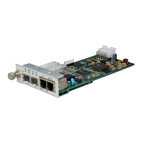
Converter is Raisecom’s self-developed IEEE802.3ah OAM-capable module, which implements Ethernet signal electrical-optical conversion. RC552-FE(A) module can be inserted into Raisecom’s 3U 16-slot chassis, coexisting with other RC series media converters; and also can be inserted into single slot chassis to act as a standalone device. -
Page 8: Chapter 3 Technical Specification
Chapter 3 Technical Specification 2.1 Basic Specification Dimensions 25mm×91mm×172mm (height×width×depth) Optical interface Working temperature 0~45℃ (℃) Storage temperature -40~80℃ (℃) Power consumption <5W (W) Working humidity 5%~90% non condensing 2.2 Optical Interface Specification Optical Interface RJ45 UTP Interface Model Launch Working Receiving Receiving... -
Page 9: Chapter 4 Installation Preparation And Connection
When back-to-back connecting media converters, the rules mentioned in 3.3 Connecting the Fiber Interface of Media Converter must be followed. Regarding to RC552-FE media converter, it is recommended to follow the table below. (if the connecting rules in below table cannot be met, please disable remote management function) -
Page 10: Connecting Media Converters To Ethernet Devices (Utp Interface)
RC552-FE(A)-SS25-Master RC552-FE(A)-SS23-Slave 3.5 Connecting Media Converters to Ethernet Devices (UTP Interface) When connecting media converters to other Ethernet devices, please pay attention that the length of UTP cable cannot exceed 100 meters. When the UTP interface is at auto-negotiation status, auto-MDI/MDIX function is also enabled in the mean time. -
Page 11: Eligible Power Supply
3.8 Eligible Power Supply AC: 220V/50Hz DC: -48V Page 11 of 25... -
Page 12: Chapter 5 Status Indicators
Optical Signal Action Electrical Signal Action Remote Equipment Optical Signal Detection Power Supply 4.2 The Indicators of RC552-FE(A) RC552-FE(A) module’s indicators and their indications are as follows. Port Name Indicator Explanation Optical receiving signal ON: optical signal is detected at receiving link;... -
Page 13: Chapter 6 Device Setup
Chapter 6 Device Setup There are 3 setup DIP-switches on RC552-FE(A) module, including function configuration DIP-switch SW21, copper interface configuration DIP-switch SW20, and fiber interface configuration DIP-switch SW22. 5.1 Copper Interface Configuration DIP-switch SW20 SW20 is a 4-bit DIP-switch, including auto-negotiation enable/disable, speed 100M/10M, and full/half duplex mode. -
Page 14: Fiber Interface Configuration Dip-Switch Sw22
If no receiving optical signal is detected, shut down the fiber interface. Fiber interface ALS Note: this function only takes effect when OAM disable/enable is disabled. ALS function is disabled. If no receiving optical signal is detected, shut down local copper interface; if remote module Fiber interface to copper has enabled copper interface to fiber interface interface fault propagation... -
Page 15: Chapter 7 Network Management Features
Chapter 7 Network Management Features 6.1 Review the Module When RC552-FE(A) module is inserted into 16-slot chassis with management agent card, customers can review the module status and also configure the module. The following parameters can be reviewed or configured. Number... -
Page 16: Loopback Test
interface speed, fault propagation, and etc. However, SLAVE module cannot be configured locally, buy only remotely through MASTER module. That is to say, if SLAVE module is inserted into 16-slot chassis with management card, customers will only be able to review its status rather than to configure it. 6.3 Loopback Test For central office module, customers can enable or disable loopback test through ‘module loopback test’... -
Page 17: Chapter 8 Configure And Manage Rc552-Fe(A) Through Cli
Log on to RC552-FE(A) module RC552-FE(A) console port default setup is [baud rate: 9600; data bit: 8; parity: 0; stop bit: 1; flow control: none], and VT100 terminal. Before logging on to the module, these parameters shall be applied to the terminal or workstation. -
Page 18: Display The Module Status
Press ‘enter’ button, and input the default password ‘1234’ in command line prompt to enter module management interface. Note: lower-case input command will be effective; press ‘ESC’ to back to upper level menu from current sub-menu. In order to operate in console interface, the menu options shall be chosen by figures. 7.2.2 Display the Module Status Choose ‘1’... -
Page 19: Display The Module Fault Propagation Status
Note 1: when RC552-FE(A) is working under SLAVE mode, only ‘remote module inside loopback’ and ‘remote module outside loopback’ can be performed; when working under MASTER mode, all ‘CO module inside loopback’, ‘CO module outside loopback’, and ‘remote module outside loopback’... -
Page 20: Fpga Firmware Online Upgrade
Fx-Re (fiber interface ALS): when enabled and no local optical receiving signal is detected, shut down fiber interface transmission. Note that this function only takes effect when remote OAM is disabled. Fx-Tp (fiber interface to copper interface fault propagation): when enabled and no local optical receiving signal is detected, shut down local copper interface;... - Page 21 Choose ‘1’ in sub-menu, download FPGA firmware file from PC console to U34 flash memory (the file transfer protocol of console is X-modem). As a backup file, it will not change after manufacturing. If the IAP of FPGA fails and the firmware file in U35 flash memory is broken, the firmware file in U34 flash memory will be used to start FPGA.
-
Page 22: Exit The Console
Choose ‘3’ in sub-menu to boot FPGA. Choose ‘4’ in sub-menu to upgrade the FPGA firmware of remote RC552-FE(A). It only takes effect when the module is under MASTER mode. The general upgrade process of FPGA firmware is as follows. -
Page 23: Chapter 9 Ieee802.3Ah Oam Functions
8.2 OAM Discovery If RC552-FE(A) is configured to SLAVE mode, it is the passive terminal in OAM. After connecting with OAM active device, RC552-FE(A) will wait for OAM active device to originate OAM discovery process. After OAM discovery success, it is able to implement other OAM functions. -
Page 24: Appendix A. Faq
Answer: on such condition that the copper interface of RC552-FE(A) is auto-negotiation and the connected device is not, RC552-FE(A) speed will be negotiated to the same as connected device, while duplex mode will be decided by configuration. In this situation, the copper interface of RC552-FE(A) shall be manually configured to 10M half duplex or auto-negotiation (speed) half duplex. - Page 25 Address: 620 Haitai Tower, Haidian District, Beijing, China 100083 Phone: (8610)-82884499 Fax: (8610)-82885200 Http://www.raisecom.com Email: export@raisecom.com Technical Support: (8610)-82883305 Page 25 of 25...
Need help?
Do you have a question about the RC552-FE and is the answer not in the manual?
Questions and answers