Advertisement
Quick Links
See also:
Owner's Manual
Advertisement

Related Manuals for Bowflex TC5500


Summary of Contents for Bowflex TC5500
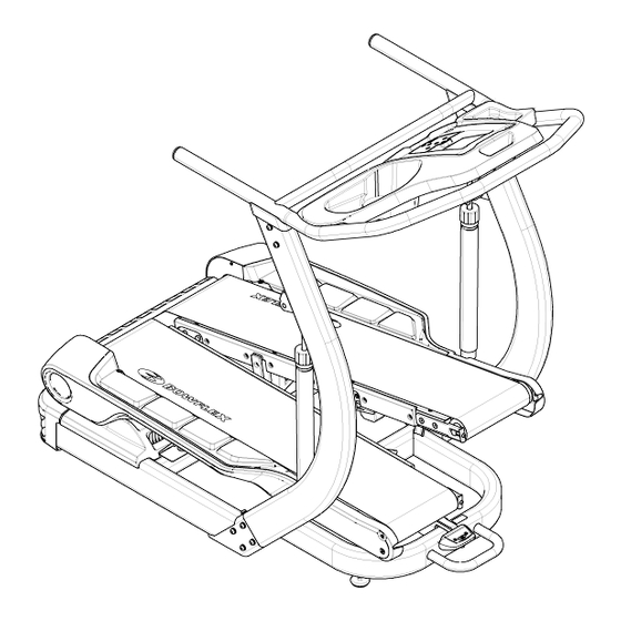
- Page 1 Bowflex® Bowflex® T T T readClimber® Bowflex® readClimber® readClimber® TC5500 TC5500 TC5500 001-7320–040109B...
-
Page 2: Table Of Contents
Table of Contents Before Assembly Parts Assembly Specifications Important Safety Instructions Contacts Tools Instructions de montage Hardware Before Assembly Select where you are going to locate your machine. The best location is on a hard, level surface. For best results, assemble your TreadClimber machine in the location where you intend to use it. -
Page 3: Important Safety Instructions
Important Safety Instructions This icon means a potentially hazardous situation which, if not avoided, could result in death or serious injury. Obey the following warnings: Read and understand all warnings on this machine. Carefully read and understand the Assembly Manual. •... -
Page 4: Tools
Tools • • • 13mm Open End Wrench or Adjustable Wrench (not included) • • • #2 Phillips Head Screwdriver (not included) • • • Utility Knife or Scissors (not included) • • • 5mm Hex Wrench (included) Hardware Item Description M8 x 20 Hex Head Bolt M8 x 20 Button Head Hex Screw... -
Page 5: Parts
Parts 3 BOXES BOX 1 Item Description Handle Junction Cover Console/Handlebar Assembly Rear Cover Cylinder Manual Pack Hardware Card Power Cord Motor Cover 5 5 5... - Page 6 BOX 2 Item Description Treadle Assembly 6 6 6...
- Page 7 BOX 3 Item Description Base Upright, Right Upright, Left 7 7 7...
-
Page 8: Assembly
Assembly Step 1: Attach Handle to Base NOTE: Hardware is pre-installed and not on Hardware Card. 8 8 8... - Page 9 Step 2: Attach Treadle Assembly to Base 9 9 9...
- Page 10 Step 3: Attach Motor Cover to Base Assembly 10 10 10...
- Page 11 Step 4: Secure Motor Cover to Base Assembly 11 11 11...
- Page 12 Step 5: Attach Junction Covers and Uprights to the Console/Handlebar Assembly NOTE: Do not crimp the Console Cable. 12 12 12...
- Page 13 Step 6: Run the Console Cable through the Base Assembly 13 13 13...
- Page 14 Step 7: Attach the Console/Handlebar/Upright Assembly to Base Assembly 14 14 14...
- Page 15 Step 8: Attach Cylinders to Uprights and then Treadle NOTE: Hardware is pre-installed and not on Hardware Card. The single, white arrow on top of the cylinders must point up and to the rear of the machine. Be sure to attach cylinder to upright before Treadle.
- Page 16 Step 9: Connect the Console Cable to Rear of Machine 16 16 16...
- Page 17 Step 10: Attach Rear Cover NOTE: Push the excess Console Cable inside the frame and then attach Rear Cover. Be sure the safety tabs on the upper-inside of the Rear Cover snap onto the Base Assembly. 17 17 17...
- Page 18 Step 11: Connect Power Cord Final Inspection Inspect your machine to ensure that all fasteners are tight and components are properly assembled. Do not use or put the machine into service until the machine has been fully assembled and inspected for correct performance in accordance with the Owner’s Manual.
-
Page 19: Contacts
Contacts NORTH AMERICA EUROPE, MIDDLE EAST & AFRICA Customer Service International Customer Service Tel: (800) 605–3369 Nautilus International GmbH E-mail: tcinquiries@nautilus.com Albin-Köbis-Str. 4 51147 Köln Tel: + 49 02203 2020 0 Fax: + 49 02203 2020 45 45 CORPORATE HEADQUARTERS E-mail: technics@nautilus.com Nautilus, Inc. - Page 20 Printed in China © 2009 Nautilus, Inc., All rights reserved ™ and ® indicate a trademark or registered trademark. Nautilus, Inc. (www.nautilus.com) trademarks include NAUTILUS®, BOWFLEX®, STAIRMASTER®, SCHWINN® and UNIVERSAL® and respective logos. Other trademarks are the property of their respective owners.
Need help?
Do you have a question about the TC5500 and is the answer not in the manual?
Questions and answers