Table of Contents
Advertisement
Advertisement
Table of Contents

Related Manuals for Paradox Grafica DNE-K07


Summary of Contents for Paradox Grafica DNE-K07
- Page 1 DNE-K07 Reference and Installation Manual...
-
Page 3: Table Of Contents
TABLE OF CONTENTS INTRODUCTION................2 Specifications ..................3 Navigation....................3 INSTALLATION ................4 Viewing Angle..................4 Keypad Cover Clearance ............... 4 Mounting the Metal Wall Plate..............5 Connecting Grafica................. 5 Mounting Grafica ..................6 Unmounting Grafica................8 PROGRAMMING ................9 Entering Module Programming Mode............. 9 Programming Methods ................. -
Page 4: Introduction
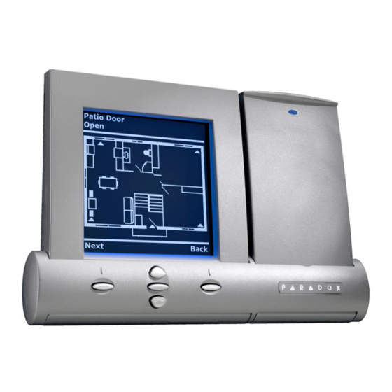
1.0 INTRODUCTION Grafica is the most advanced keypad and communication device in the security industry. Developed to resolve operational flaws with security system keypads, Grafica offers the ability to view zone locations on a floor plan drawing through its graphic LCD screen and provides simple menu-driven commands that eliminate the need of user manuals thus reducing training time to a minimum. -
Page 5: Specifications
1.1 SPECIFICATIONS Power input: Typically 12 to 16 Vdc, 130mA maximum. Power indication: Blue LED on. Locate indication: Blue LED flashes. Bus fault indication: Fault indication message will appear on screen. Anti-tamper switch: Yes. Display: Film Super Twisted Nematic. (Black and white contrast). 128 X 128 pixels. Under ESD conditions the screen may go blank. -
Page 6: Installation
2.0 INSTALLATION 2.1 VIEWING ANGLE The Grafica keypad’s graphic LCD is best viewed from a direct angle between a range of 20° and -10° (Figure 2). Be sure to install the Grafica keypad at a height and in a direction that provides the best viewing angle. -
Page 7: Mounting The Metal Wall Plate
2.3 MOUNTING THE METAL WALL PLATE 1) Place metal wall plate to desired position. 2) Drill and insert screws into holes labeled “A” as shown in Figure 3. Figure 3: Metal Wall Plate (Used also for electrical box) C (for clip) A (Used also for electrical box) 2.4 CONNECTING GRAFICA You can connect Grafica to the DigiplexNE control panel’s... -
Page 8: Mounting Grafica
Figure 4: Connection Overview To other modules Communication--- Grafica (partial view) To DigiplexNE control panel 2.5 MOUNTING GRAFICA 1) Place Grafica’s back plate flush against the mounted metal wall plate. 2) Slide the Grafica’s open slots labeled “D” (Figure 5 on page 7) onto the metal wall plate’s tabs labeled “B”... - Page 9 Figure 5: Grafica Back Plate Clip Figure 6: Mounting Grafica to Wall Plate Metal wall plate Optional screw inserted here DigiplexNE Grafica Keypad Module...
-
Page 10: Unmounting Grafica
2.6 UNMOUNTING GRAFICA 1) If required, remove the optional screw. 2) Gently lift the unit upwards with your hands until it separates from the metal wall plate (Figure 7). Figure 7: Unmounting the Grafica Metal wall plate 8 Reference & Installation Manual... -
Page 11: Programming
Grafica can also be programmed using the WinLoad Security System Management Software. For more information, refer to the WinLoad instructions or visit our Web site at www.paradox.ca. Floor plans, tunes and graphics can be downloaded to Grafica using Winload V2.2 or higher and NEware V2.0 or higher. -
Page 12: Programming Methods
The serial number is located on Grafica’s PCB or enter section [0000] in Step 3 to view Grafica’s version and serial number. 3.2 PROGRAMMING METHODS The following methods can be used when programming the Grafica keypad: 3.2.1 F EATURE ELECT ROGRAMMING You can program sections by enabling or disabling options. -
Page 13: System Options
4.0 SYSTEM OPTIONS The following sections detail the options that can be programmed for Grafica. 4.1 PARTITION ASSIGNMENT [001]: O ECTION PTIONS Each keypad in the system can be assigned to one or more partitions. In section [001], options [1] to [8] represent partitions 1 through 8 respectively. -
Page 14: Display Entry Delay
4.4 DISPLAY ENTRY DELAY [002]: O ECTION PTION Based on the user's needs, an Entry Delay Timer can be programmed to provide the user time to enter their User Access Code before the alarm is triggered. If this option is enabled, the Entry Delay Timer's countdown will appear on the graphic LCD screen next to the hourglass icon. -
Page 15: Exit Delay Beep
Grafica will go from Confidential Mode into Normal Mode once a key is pressed or a code is entered. In normal mode, Grafica displays the date, time, as well as the status of open zones for every partition that the keypad is assigned. In addition, Alarm Memory Display, Bypassed zones and the Trouble Display can be displayed. -
Page 16: Beep On Trouble
via the communication bus. Option [8] OFF = Grafica’s anti-tamper switch is disabled. (Default) Option [8] ON =Grafica’s tamper is enabled. 4.8 BEEP ON TROUBLE [003]: O ECTION PTIONS Potential troubles have been sorted into groups. With these options enabled, the keypad will emit an intermittent beep tone whenever a trouble condition occurs from one of the Trouble Groups. -
Page 17: Confidential Mode Timer
4.8.3 M ODULE AND ROUBLE [003]: O ECTION PTION Option [3] OFF = Beep disabled (Default). Option [3] ON = Beep on: Module and Bus Troubles. 4.8.4 A ROUBLE [003]: O ECTION PTION Option [4] OFF = Beep disabled (Default). Option [4] ON = Beep on: all Zone Troubles. -
Page 18: Copy To Memory Key
Figure 8: Memory Key Connector (partial view) 4.11 COPY TO MEMORY KEY [110] ECTION Use this section to copy Grafica sections [001] to [004], all zone labels, area labels, and user labels to the Memory Key. To copy the contents: 1) Insert the Memory Key onto the keypad’s connector. - Page 19 Figure 9: PMC-3 Jumper Settings Only the PMC-3 Memory Key will function with Grafica keypads. DigiplexNE Grafica Keypad Module...
-
Page 20: Programming Sections
5.0 PROGRAMMING SECTIONS = Default Setting Section [001]: Keypad Partition Assignment Option ARTITION ISABLED NABLED ARTITION ISABLED NABLED ARTITION ISABLED NABLED ARTITION ISABLED NABLED ARTITION ISABLED NABLED ARTITION ISABLED NABLED ARTITION ISABLED NABLED ARTITION ISABLED NABLED = Default Setting Section [002]: General Options 1 Option ISPLAY CODE ENTRY ISABLED... - Page 21 = Default Setting Section [003]: Beep on Trouble Option & C YSTEM LOCK ROUBLE ISABLED NABLED OMMUNICATOR ROUBLE ISABLED NABLED & B ODULE ROUBLE ISABLED NABLED ROUBLE ISABLED NABLED UTURE UTURE UTURE UTURE 120 seconds Default Setting Section [004]: Confidential Mode Timer Data ___/___/___ (005 to 255 seconds)
- Page 22 © 2002 Paradox Security Systems Ltd. Grafica, DigiplexNE, Winload and NEware are trademarks of Paradox Security Systems. 20 Reference & Installation Manual...
- Page 24 Printed in Canada - 08/2002 GRAFICA-EI01...
Need help?
Do you have a question about the Grafica DNE-K07 and is the answer not in the manual?
Questions and answers