Table of Contents
Advertisement
Advertisement
Table of Contents

Related Manuals for CAME ZL180 SERIES


Summary of Contents for CAME ZL180 SERIES
- Page 1 CONTROL PANEL FOR 24V OPERATORS INSTALLATION MANUAL ZL180 English...
-
Page 2: Intended Use And Application
The overall power of the motors must not exceed 300 W. 3 Reference Standards For its quality processes management Came Cancelli Automatici is ISO 9001:2000 certified, and for its environmental management it is ISO 14001 certified. Came designs and manufactures entirely in Italy. -
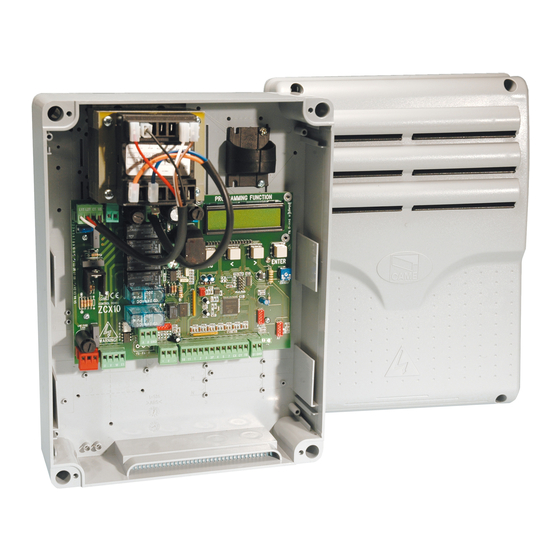
Page 3: Main Components
4.1 - DIMENSIONS, SPANS AND ANCHORING HOLES 4.2 - MAIN COMPONENTS 1 - Transformer 2 - Control unit fuse 3 - Trimmers (see page 9) 4 - Buttons for memorising the radio code 5 - Plug for the remote control frequency card 6 - Terminal board for connecting the antenna 7 - Terminal blocks for connecting accessories, control and safety... -
Page 4: Installation
5 Installation 5.1 - PRELIMINARY CHECKS Before installing do the following: • Check that the panel’s anchoring point is protected from possible blows, and that the anchoring surface is solid. Also check that the anchoring is done using the appropriate bolts, screws etc. •... -
Page 5: Electrical Connections
Insert the pressure hinges into the box (on the left or right as you wish) and set them using the provided screws and washers. 15 mm~ They must slide in order to turn Snap the cover into place onto the hinges. Close it and fix it using the provided screws. - Page 6 6.4 - POWER SUPPLY TO AND ACCESSORIES Terminals for powering the following accessories: - 24 V AC (normally alternated power) - 24 V AC (continuous power) when the emergency batteries are in operation. Overall power allowed: 34 W Power supply 230 V AC 50/60 Hz 6.3- SIGNALLING AND LIGHTING DEVICES Open gate indicator-light...
- Page 7 6.4 - CONNECTING TO THE GEARMOTORS A3024N-A5024N gearmotors 24V DC gearmotor 24V DC gearmotor featuring delayed action on opening (M1), featuring delayed action on closing (M2), Left-hand installed (inside view) Left-hand installed (inside view) - Standard installation - - Standard installation - RA-RA = Opening-speed blocker microswitch RC-RC = Closing-speed reduction...
- Page 8 F7024N gearmotors 24V DC gearmotor 24V DC gearmotor featuring delayed action on opening featuring delayed action on closing (M1), (M2), Left-hand installed (inside view) Left-hand installed (inside view) - Standard installation - - Standard installation - M = red N = black RA-RA = Opening-speed blocker microswitch RC-RC = Closing-speed reduction...
- Page 9 The ZL180 is calibrated to the F7024N or A3024N commands for gate leaves of up to 3 meters. CH1 = A5024N To command A5024N models (with gate leaves of over 3 m ) and reduce peripheral speed, do the following: a) - Set dip switches 1 and 6 to ON (and dip switches 2, 3, 4, 5 to OFF);...
-
Page 10: Common Procedure
6.5- ELECTRICAL LOCK ZL180 lets you connect, in two different modes, a 12 V (15 Wmax) electrolock and, if necessary, also activate the “Ram Blow” function. Mode 1 – Excludes use of the 2nd radio channel on B1-B2; after connecting it, operate as follows: RALL1 transformer a) - Set dip switch 6 to ON (and dip switches 1, 2, 3, 4, 5 to... -
Page 11: Safety Devices
6.6- SAFETY DEVICES DIR photocells “Partial stop” (N.C.) socket - input for safety devices such as photocells, sensitive edges and other EN 12978-compliant devices. Halts moving gate leaves and causes them to automatically close DIR photocells “Open during closing” (N.C.) socket - Input for safety devices such as photocells, sensitive edges and other EN 12978 compliant devices. -
Page 12: Command Devices
6.7- COMMAND DEVICES Stop button (N.C. socket) - Button to stop gate while excluding the automatic closing cycle. For movement to resume you must press the command button or transmitter button. Key selector and/or partial opening button (N.O. socket) - Opening of one gate leaf to allow pedestrian passage. Key selector and/or commands button (N.O. -
Page 13: Selecting Functions
7 Selecting functions DIP-SWITCH 1 ON - Automatic closing - the automatic closing timer is activated when on opening the gate leaf has reached the full open stroke. The time is preset and adjustable, and is subject to the action of any safety devices. It does not activate after a total safety “stop”... - Page 14 9 Adjusting the endstops ATI gearmotors Adjustments to carry out when Microswitch gearmotors are in release activating slide Screws for fi xing and mode: insert the release key locking/releasing the endstops and turn it clockwise. Closing microswitch Opening microswitch - OPENING ENDSTOP - ATI gearmotors Depending on the function you have assigned to the opening endstop (see paragraph 6.4, page 7) the adjustment settings will be the following: Opening Stop...
- Page 15 FAST gearmotors WARNING! Make sure you have inverted the M-N connection for THE RIGHT-HAND MOTOR, as shown on page 8. Adjustments to carry out when Lower cam fi xing and locking/release screw Upper cam gearmotors are released: insert Closing microswitch the release handle and turn it (above) counter-clockwise.
- Page 16 CLOSING ENDSTOP – LEFTHAND GEARMOTOR (INSIDE VIEW) N.B. The closing endstop can be adjusted after setting the opening microswitch. Warning: the upper cam of the operator’s endstop assembly is calibrated for gate widths of between 1.2 m to 2.2 m. - Release the gearmotor and fully close - turn the lower cam counter-clockwise, until the micro switch is the gate leaf.
- Page 17 - OPENING ENDSTOP – RIGHTHAND GEARMOTOR – INSIDE VIEW - Remove the screws from the upper cam and turn it upsidedown. Turn the lower cam counter-clockwise, until the microswitch is engaged. - Release the motor and position the gate leaf 5 cm ajar from the opening endstop - Secure the cam by tightening the central screw.
- Page 18 CLOSING ENDSTOP – RIGHTHAND GEARMOTOR – INSIDE VIEW N.B. Always fi rst adjust the opening endstop and then the closing endstop Warning: the upper cam of the operator’s endstop assembly is calibrated for gate widths of between 1.2 m to 2.2 m. - Release the gearmotor and fully close the - turn the upper cam clockwise, until the micro switch is released.
-
Page 19: Activating The Remote Control
10 Signal LED LIST OF CONTROL LED SIGNALS OF THE COMMAND AND SAFETY DEVICES: - «ALIM» Green LED. Normally on, because it signals the cards proper power rate. - «PROG» Red LED. Normally off. During the remote control’s activation procedure, it turns on and blinks. It blinks faster when combined with LEDs C1/C3/ST - «C1»... - Page 20 11.3 - TRANSMITTERS ATOMO AT01 • AT02 See instructions attached to AF43SR radiofrequency card AT04 TOUCH TOP-432NA • TOP-434NA TCH 4024 • TCH 4048 TOP-432S TOP-302 A • TOP-304A TOP-432 A • TOP-434A T432 • T434 • T438 T132 • T134 • T138 TAM-432SA T152 •...
- Page 21 11.4 - MEMORISATION CH1 = Channel for direct command to a function of the the gearmotor’s card, (“open only / “open-close-invert” or “open-stop-close-stop” command, depending on the choice made on DIP switches 2 and 3). CH2 = Channel for direct command an accessory device connected to B1-B2. 1) Keep the CH1 button on the electronic card pressed.
-
Page 22: Ec Declaration Of Conformity
31030 Dosson di Casier - Treviso - ITALY tel (+39) 0422 4940 - fax (+39) 0422 4941 internet: www.came.it - e-mail: info@came.it Declares under its own responsibility that the equipments for automatic garage doors and gates listed below: CONTROL PANELS FOR SWING GATES ZL180 …... -
Page 23: This Page Left Intentionally Blank
THIS PAGE LEFT INTENTIONALLY BLANK THIS PAGE LEFT INTENTIONALLY BLANK... - Page 24 (+34) 91 52 85 009 Jebel Ali Free Zone - Dubai Dubai (+34) 91 46 85 442 (+971) 4 8860046 (+971) 4 8860048 CAME United Kingdom Ltd. CAME United Kingdom Ltd. GREAT BRITAIN RUSSIA CAME Rus CAME Rus Unit 3 Orchard Business Park...
Need help?
Do you have a question about the ZL180 SERIES and is the answer not in the manual?
Questions and answers