Table of Contents
Advertisement
Quick Links
Download this manual
See also:
Operating Manual
In the interests of user-safety (Required by safety regulations in some countries) the set should be restored to its
original condition and only parts identical to those specified should be used.
» ELECTRICAL SPECIFICATIONS ........................................................................................................ 1
» IMPORTANT SERVICE SAFETY PRECAUTION ................................................................................ 2
» LOCATION OF USER'S CONTROL .................................................................................................... 4
» INSTALLATION AND SERVICE INSTRUCTIONS ............................................................................... 5
» CHASSIS LAYOUT ............................................................................................................................ 11
» BLOCK DIAGRAM ............................................................................................................................. 12
» SCHEMATIC DIAGRAMS .................................................................................................................. 13
» PRINTED WIRING BOARD ASSEMBLIES ....................................................................................... 19
» REPLACEMENT PARTS LIST ........................................................................................................... 22
» PACKING OF THE SET ..................................................................................................................... 29
POWER INPUT ..................................................... 120 V AC 60 Hz
POWER RATING .................................................................. 105 W
PICTURE SIZE ........................................... 2,032cm
CONVERGENCE ............................................................. Magnetic
SWEEP DEFLECTION .................................................... Magnetic
FOCUS ............................................... Hi-Bi-Potential Electrostatic
INTERMEDIATE FREQUENCIES
Picture IF Carrier Frequency ..................................... 45.75 MHz
Sound IF Carrier Frequency ...................................... 41.25 MHz
Color Sub-Carrier Frequency .................................... 42.17 MHz
AUDIO POWER ..................... 1.5 W+1.5 W (at 10% distortion and
SHARP CORPORATION
SERVICE MANUAL
MODEL
CONTENTS
ELECTRICAL SPECIFICATIONS
SPEAKER
SIZE ...................................................................... 8 cm (Round)
2
(315sq inch)
VOICE COIL IMPEDANCE ............................. 32 ohm at 400 Hz
ANTENNA INPUT IMPEDANCE
VHF/UHF ..................................................... 75 ohm Unbalanced
TUNING RANGES
VHF-Channels ............................................................... 2 thru 13
UHF-Channels ............................................................ 14 thru 69
CATV Channels ........................................................... 1 thru 125
(Nominal)
Dual CH Operate)
Specifications are subject to change without
prior notice.
This document has been published to be used for after
sales service only.
The contents are subject to change without notice.
1
COLOR TELEVISION
Chassis No. C/D-BM
25C340
(EIA, Channel Plan U.S.A.)
25C340
Page
Advertisement
Table of Contents

Related Manuals for Sharp 25c340


Summary of Contents for Sharp 25c340
-
Page 1: Table Of Contents
25C340 SERVICE MANUAL COLOR TELEVISION Chassis No. C/D-BM 25C340 MODEL In the interests of user-safety (Required by safety regulations in some countries) the set should be restored to its original condition and only parts identical to those specified should be used. -
Page 2: Important Service Safety Precaution
25C340 IMPORTANT SERVICE SAFETY PRECAUTION Service work should be performed only by qualified service technicians who are thoroughly familiar with all safety checks and the servicing guidelines which follow: WARNING X-RADIATION AND HIGH VOLTAGE LIMITS 1. For continued safety, no modification of any circuit 1. -
Page 3: Safety Notice
25C340 IMPORTANT SERVICE SAFETY PRECAUTION (Continued) • Connect the resistor connection to all exposed metal BEFORE RETURNING THE RECEIVER parts having a return to the chassis (antenna, metal (Fire & Shock Hazard) cabinet, screw heads, knobs and control shafts, escutcheon, etc.) and measure the AC voltage drop Before returning the receiver to the user, perform across the resistor. -
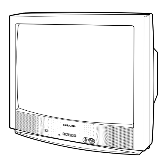
Page 4: Location Of User's Control
25C340 LOCATION OF USER'S CONTROL Front Panel POWER Press → On. VIDEO/AUDIO IN2 TERMINALS Press again → Off. SENSOR AREA FOR REMOTE CONTROL CHANNEL UP/DOWN MENU ( ) Selects next higher channel. Press → Accesses MAIN MENU. VOLUME UP/DOWN ( ) Selects next lower channel. -
Page 5: Installation And Service Instructions
25C340 INSTALLATION AND SERVICE INSTRUCTIONS Note: (1) When performing any adjustments to resistor controls and transformers use non-metallic screwdrivers or TV alignment tools. (2) Before performing adjustments, the TV set must be on at least 15 minutes. HIGH VOLTAGE CHECK CIRCUIT PROTECTION The receiver is protected by a 4.0A fuse (F701),... - Page 6 25C340 For adjustments of this model, the bus data is converted to various analog signals by the D/A converter circuit. Note: There are still a few analog adjustments in this series such as focus and master screen voltage. Follow the steps below whenever the service adjusment is required.
- Page 7 25C340 Below are the adjustments ranges and initial values for FIX VALUE category. FIX VALUE DATA SERVICE ADJUST ITEM INITIAL VALUE (Hex) POSITION RANGE OPTION 1 00-FF OPTION 2 00-FF E-SAVE 00-3F TUNER SETUP 00, 01 R-TONE RD 00-7F R-TONE BD...
- Page 8 25C340 SIGNAL DATA SERVICE ADJUST ITEM ADJUSTMENT CONTENTS POSITION RANGE INITIAL VALUE RF AGC 00-3F VIDEO LEVEL 00-07 "01": Y-MUTE, "02": V-STOP & Y-MUTE Y-MUTE 00-03 "03": Activate color killer circuit. SUB BIAS 00-FF Must be "30" R-BIAS 00-FF G-BIAS...
-
Page 9: Service Adjustment
25C340 Ë SERVICE ADJUSTMENT 4. Select the service adjustment "S03" and set the data Note: Before making the service adjustment, make the bus data settings. value to "01" to turn off the luminance signal (Y-mute). +B Adjustment 5. Select the service adjustment "S14" and adjust the data value to obtain 2.35 volts as shown in Figure B. -
Page 10: Mts Adjustment
25C340 Ë MTS ADJUSTMENT Vertical-Size, V-Linearity and MTS Level Adjustment 1. Feed the following monaural signal to pin (14) of V-S Correction Adjustments IC3001. 1. Receive a good local channel. Monaural signal: 300Hz, 245mVrms 2. Enter the service mode DEF category and select the 2. -
Page 11: Chassis Layout
25C340 CHASSIS LAYOUT PWB-B PWB-A... -
Page 12: Block Diagram
25C340 BLOCK DIAGRAM... -
Page 13: Schematic Diagrams
25C340 DESCRIPTION OF SCHEMATIC DIAGRAM WAVEFORM MEASUREMENT CONDITIONS: NOTES: 1. Photographs taken on a standard gated color bar 1. The unit of resistance "ohm" is omitted. (K=k Ω =1000 Ω , M=M Ω ) signal, the tint setting adjusted for proper color. The wave shapes at the red, green and blue cathodes of 2. - Page 14 25C340 SCHEMATIC DIAGRAM: MAIN-1 Unit...
- Page 15 25C340...
- Page 16 25C340 SCHEMATIC DIAGRAM: MAIN-1 Unit...
- Page 17 25C340...
- Page 18 25C340 SCHEMATIC DIAGRAM: CRT Unit...
-
Page 19: Printed Wiring Board Assemblies
25C340 PRINTED WIRING BOARD ASSEMBLIES PWB-B: CRT Unit (Wiring Side) - Page 20 25C340 PWB-A: MAIN Unit (Wiring Side)
- Page 21 25C340 PWB-A: MAIN Unit (Chip Parts Side)
-
Page 22: Replacement Parts List
IX3528CE IC2040 VHIPST994C/-1+ PST994C in USA: Contact your nearest SHARP Parts Distributor to order. VHIBR24L16F-1Y BR24L16F IC2101 For location of SHARP Parts Distributor, Please call Toll- IC3001 VHICXA2194Q-1Y CXA2194Q Free; 1-800-BE-SHARP IC3371 VHIAN7511//-1 AN7511 « MARK: SPARE PARTS-DELIVERY SECTION TRANSISTORS... -
Page 23: Main Unit
25C340 « « Description Ref. No. Part No. Description Code Ref. No. Part No. Code C356 VCKYCY1HB332KY 3300p 50V Ceramic PWB-A: DUNTKA462WEA2 C357 VCEA0A1HW106M+ MAIN UNIT C358 VCEA0A1HW106M+ C361 VCEA0A1CW227M+ C401 VCCCCY1HH470JY Ceramic DIODES C411 VCEA0A1AW108M+ 1000 D708 VHD1SS119//-1Y Diode... - Page 24 25C340 « Description « Description Ref. No. Part No. Code Ref. No. Part No. Code VRS-CY1JF000JY 1/16W M-Ox. PWB-A: DUNTKA462WEA2 VRS-CY1JF000JY 1/16W M-Ox. VRS-CY1JF000JY 1/16W M-Ox. MAIN UNIT VRS-CY1JF000JY 1/16W M-Ox. RJ10 VRS-CY1JF000JY 1/16W M-Ox. CAPACITORS RJ11 VRS-CY1JF000JY 1/16W M-Ox.
- Page 25 25C340 Ref. No. Part No. « Description Code Ref. No. Part No. « Description Code R746 VRS-CY1JF562JY 5.6k 1/16W M-Ox. PWB-A: DUNTKA462WEA2 R747 VRS-CY1JF682JY 6.8k 1/16W M-Ox. R752 VRD-RA2BE392JY 3.9k 1/8W Carbon MAIN UNIT U R758 VRS-RG2HC100J+ 1/2W M-Ox. R762...
-
Page 26: Crt Unit
25C340 « Description Ref. No. Part No. Code Ref. No. Part No. « Description Code MISCELLANEOUS PARTS PWB-A: DUNTKA462WEA2 RY701 RRLYJ0081CEZZ Relay MAIN UNIT F701 QFS-B4023CEZZ FUSE - 4A 125V FB601 RBLN-0047CEZZY FERRITE BEAD RESISTORS FH701 QFSHD1013CEZZ+ FUSE CLIP [M-Ox.··· Metal Oxide, M-Film ··· Metal Film]... -
Page 27: Supplied Accessories
25C340 « Description Ref. No. Part No. Code Ref. No. Part No. « Description Code PWB-B: DUNTK9510WEV1 SUPPLIED ACCESSORIES CRT Unit RESISTORS [M-Ox.··· Metal Oxide, M-Film ··· Metal Film] TINS-B189WJZZ operation manual R869 VRD-RA2BE121JY 1/8W Carbon RRMCGA035WJSB Infrared R-C Unit... -
Page 28: Packing Of The Set
25C340 PACKING OF THE SET Polyethylene Bag Operation Manual Infrared R/C Unit Batteries Polyethylene Sheet Buffer Material FRONT Packing Case Use tape to fix the top side of packing case. REAR Bar Code Label Use 12 staples to fix the bottom side of packing case. - Page 29 QRC0021-U April. 2004 Modify : SEMEX Design and Production Information SHARP ELECTRONICA MEXICO S. A. DE C. V. Design : SEM Quality & Reliability Control Center Production : SEMEX Blvd. SHARP No. 3510 Parque Industrial Rosarito...