
Summary of Contents for Ldsolar LD2420C
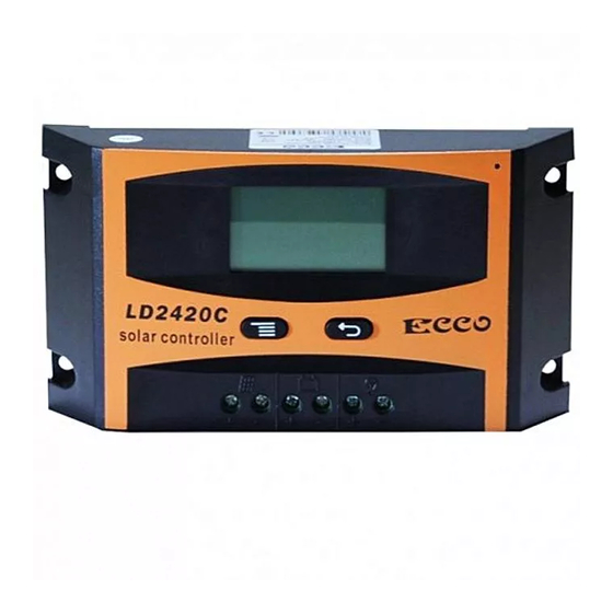
- Page 1 Instruction of Solar Charge Controller User’s Manual 12V/24V 10A/20A Dear Users: Thank you for selecting our product. Please read this manual carefully before you use this product.
- Page 2 The controller is for off-grid solar system and control the charging and discharging of the battery. Main function is protecting battery. The intelligent charging process has been optimized for long battery life and improved system performance. Major Functions The features are listed below: ...
-
Page 3: Important Safety Information
charging and discharging voltage automatically, improving the battery lifetime. Roundly reverse connected protection. Solar Panels, Battery, Solar Charge Controller positive poles are all connected together, adopting negative MOSFET in series control circuit. Important Safety Information It is better to install the controller in the room. If installed the controller outside, please keep the environment dry, avoid direct sunlight. - Page 4 short circuit the positive and negative pole of battery. Suggest to adding a fuse between battery and controller. (Slow motion type, the action current of the fuse should be 1.5 times rated current of controller.) The suggestion of using The controller could detect the temperature of environment to adjust the voltage of charging, so that the controller should be closed to battery as near as...
- Page 5 The feature of LCD graphic symbol The default night display of controller: When the solar panel input voltage have been detected by controller less than sensor identification point voltage, this graphic symbol will be light. The default daytime display of controller: When the solar panel input voltage have been detected by controller more than sensor identification point voltage, this graphic symbol will be light.
- Page 6 The indicator of battery parameter: When the battery parameter was displaying, this graphic symbol will be light. For example the voltage of battery, temperature of battery. The indicator of load parameter: When the load parameter was displaying, this graphic symbol will be light.
-
Page 7: Installation Instructions
have output, this graphic symbol will be light. 14. The indicator of capacity of battery: When the battery was in different capacity, the strip-type will show. 15. The indicator of charge status: When the controller is charging, the symbol will be light, float charge will be flash, no charging no display. - Page 8 Controller Connection All terminals are in tight status after factory, in order to well connected, please loose all terminals at first. The following order of connection please do not free change, or cause system voltage recognition fault. As figure, first connected the battery to controller correct poles.
- Page 9 connection is correct, the LCD displaying will show battery voltage and other technical data. If LCD no indicate, please check the fault. The length of cable between battery and controller as shorter as possible. Suggest to 30CM -100CM. short circuit happened terminals of controller, it will be result in...
- Page 10 not connect any load with controller at that time, or the load and controller will be destroyed. As figure, connected solar panels with controller correctly, if the connection is successful and sunshine is full, the LCD will show solar panel and an arrow from solar panel to battery will be light.
-
Page 11: Main Interface
positive combined together. If your solar system needs ground connection, please let positive ground connection. Warning: For some force to ground connected system, such solar communication system, portable solar system, they are negative ground connected, at this time please do not positive connected, or can cause short circuit. - Page 12 “ ”more than 5s at main interface, it will speed auto exchange. Loose button will stop speed. Press “ ”under main interface could open or close the load output。 Press “ ”button could join into next menu under main interface...
- Page 13 Float Voltage Set up This parameter is High Voltage Disconnection (HVD) voltage.(Boost state voltage will be increase 0.6V base on HVD) The controller will be started PWM function at this point(HVD), limited voltage rising. Press “ ” join in float voltage menu. Long press...
- Page 14 “ ”button≥5S, the parameter on the interface will be flash, here is set up state. Loose the button, press“ ” button again could operate plus data, press“ ” button could operate minus data. After finish the needed technical data, long press“ ”button again ≥5S, the parameter save and come out set up state.
- Page 15 working. At the same time, the status of controller is in lock. Users have to charge the battery, when the battery voltage is higher than LVD voltage or press“ ”button force to release. The load output will be back. The procedure is same with (a). Above a、b、c three parameter default data was fully considered by designer according to the actual use.
- Page 16 time set to ≤23H, it means the load start timer or sensor function. If the battery capacity is enough, the load will be started at sunset. The load will work under timer setting hours or stop working till sunrise. When the load join into timer or sensor mode, if the reset working time more than actual night time, the load output will be closed at sunrise, although the working time is not...
- Page 17 When battery voltage is more than 18V, the controller will be auto change to 24V system with 24V control data.When battery voltage is less than 18V, the controller will be auto change to 12V system with 12V control data. “ ”, If the system voltage is set to the controller will be...
- Page 18 come back or press “ ”button force to unlock at main interface. Battery Over Voltage Disconnection (OVD) When the voltage of battery more than 16.5V, the over voltage protection will be started. The load cut off, at the same time the load and warning symbol flash.
- Page 19 High Voltage Disconnection Protection (HVD) When battery charged 13.8V, function will started, the charge symbol will be flash, and the voltage of battery has been limited. Common Fault and Handling Fault Phenomen Possible Reason Solution Battery Low Battery Please confirm the voltage Reverse...
-
Page 20: Technical Data
Over Current or high surge power rated design, the surge Protection power of load too high. Technical Data Mode LD2420C System Voltage 12V/24V Max. Input Voltage of solar panel Self-consumption ≤12mA... - Page 21 Max. charge current Max. discharge current 11.0V ADJ 9V….12V ;×2 24V 12.6V ADJ 11V….13.5V ;×2 24V Float Voltage 13.8V ADJ 13V….15V ;×2 24V 14.4V ; ×2 Battery Voltage Boost charging less than 12Vstart boost charging 2 hours Battery Over 16.5V ; ×2 24V Voltage Protection ReverseConnection Protection...
Need help?
Do you have a question about the LD2420C and is the answer not in the manual?
Questions and answers