Lexmark CX825 Service Manual
Hide thumbs
Also See for CX825:
- Service manual (155 pages) ,
- User manual (317 pages) ,
- Quick start manual (15 pages)
Table of Contents
Advertisement
Quick Links
See also:
User Manual
Advertisement
Table of Contents

Related Manuals for Lexmark CX825


Summary of Contents for Lexmark CX825
-
Page 1: Service Manual
CX825, CX860, XC8155, and XC8160 7564-336, -337, -536, -537, -596, -598 Service Manual • Start diagnostics • Maintenance • Safety and notices • Trademarks • Index January 25, 2016 www.lexmark.com P/N 12G3414... -
Page 2: Product Information
Trademarks Lexmark and the Lexmark logo are trademarks of Lexmark International, Inc., registered in the United States and/or other countries. PCL® is a registered trademark of the Hewlett-Packard Company. PCL is Hewlett-Packard Company’s designation of a set of printer commands (language) and functions included in its printer products. -
Page 3: Table Of Contents
7564 Table of contents Product information..................2 Edition notice....................2 Notices and safety information..............23 Laser notice.................................23 Avis relatif à l'utilisation du laser........................23 Notificació del làser............................23 Aviso de láser..............................23 Aviso sobre laser............................... 24 Avvertenze sui prodotti laser......................... 24 Laserinformatie..............................24 Lasererklæring.............................. - Page 4 7564 安全信息........................... 31 安全情報........................... 32 安全資訊........................... 32 Preface......................33 Conventions................................33 General caution statements..........................33 General information................... 35 Printer model configurations.......................... 35 Finding the serial number..........................36 Paper and specialty media guide........................37 Supported paper sizes, types, and weights ......................37 Paper guidelines................................40 Using specialty media ..............................
- Page 5 7564 Fixing scan quality issues..........................79 Dark image quality (using the ADF or scanner) check ..................79 Vertical lines (process direction using the ADF) check ..................81 Spots (using the flatbed scanner) check ....................... 82 ADF skew check ................................83 Media damage (using the ADF) check........................84 Wavy edge (ADF 2nd side scan) service check ....................
- Page 6 7564 40y paper jams ................................257 41y paper jams................................266 42y paper jams ................................273 43y paper jams................................293 45y paper jams ................................298 46y paper jams ................................344 47y paper jams................................358 48y paper jams ................................376 User attendance messages......................... 388 User attendance messages (0‑99) ........................388 Cartridge or photoconductor error service check....................389 Mismatched paper size service check ........................390 Insufficient memory service check ........................391...
- Page 7 7564 374–383 errors ................................512 Service option software error service check ......................521 Symptoms................................. 524 Printer symptoms...............................524 Multiposition staple, hole punch finisher symptoms..................534 2-bin mailbox symptoms............................550 Input option symptoms ............................559 Staple finisher symptoms ............................563 Service menus................... 571 Understanding the printer control panel....................571 Using the control panel ............................
- Page 8 7564 Printhead alignment adjustment ...........................596 Registration adjustment............................601 Color alignment adjustment ..........................602 MSHPF tamper alignment adjustment.........................603 Removal procedures............................605 Left side removals............................605 Left upper cover removal ............................605 Fuser removal................................606 Transfer roller removal .............................607 Duplex drive gears removal ..........................608 Duplex release latch removal ..........................
- Page 9 7564 Separator pad removal ............................655 Door rod cover removal............................656 Sensor (door interlock) removal ..........................657 HVPS fan removal ..............................658 Main HVPS removal ..............................661 PC unit/developer door removal ...........................663 Lower front cover removal............................664 Paper feeder removal...............................665 Sensor (auto alignment) removal ..........................667 Sensor (TPS) removal ...............................667 TPS sensor wiper removal ............................668 Developer/PC unit CMY wiper rail removal......................668 Developer/PC unit K wiper rail removal ......................669...
- Page 10 7564 ADF rear cover removal............................. 711 ADF removal ................................. 711 ADF controller board removal..........................712 ADF tray removal................................ 713 ADF front cover removal ............................713 ADF bottom door removal ............................714 Top interlock actuator removal ..........................716 ADF front drive train removal ..........................717 Motor (ADF) removal..............................
- Page 11 7564 Sensor (550-sheet tray pick roller index) removal ...................760 550-sheet tray left rail removal..........................761 Motor (550-sheet tray pass‑through) removal....................762 550-sheet tray wake up switch removal ......................763 2200-sheet tray removals..........................765 2200-sheet tray insert removal ..........................765 Bell crank removal..............................765 2200-sheet tray rail removal..........................766 Sensor (2200-sheet tray media low) removal ....................
- Page 12 7564 Staple finisher stack clamp solenoid removal ....................810 Motor (staple finisher aligner paddle) removal ....................812 Staple finisher transport gears removal .......................812 Staple finisher aligner paddle gears removal .....................814 Sensor (staple finisher upper exit roller) removal ....................816 Staple finisher exit gears removal.......................... 817 Staple finisher front upper position exit roller gears removal ................819 Staple finisher exit roller belts removal ........................821 Staple finisher tamper assembly removal......................822...
- Page 13 7564 Hole punch unit gears removal ..........................875 Sensor (hole punch unit) removal .........................876 HPT transport assembly removal ..........................878 Motor (HPT transport) removal ..........................879 HPT transport gears removal ..........................881 HPT transport drive belt removal ..........................883 HPT top cover removal ............................884 HPT transport idler roller removal ........................885 HPT top door removal..............................888 HPT lock removal ..............................888 HPT autoconnect cable removal..........................891...
- Page 14 7564 Sensor (stapler bin stack upper limit) removal ....................962 Compiler entrance belt tensioner removal......................964 Hole punch box belt removal ..........................966 Hole punch box pulley gear removal ........................967 Staging outer transport belt removal ........................969 Staging outer transport pulley gear removal ...................... 971 Motor (staging diverter) removal ...........................
- Page 15 7564 MSHPF standard bin assembly removal ....................... 1091 Staging paper guide removal.......................... 1094 Staging inner transport roller removal ......................1096 Staging diverter removal ..........................1099 Staging exit guide removal ..........................1106 Multiposition stapler assembly removals ......................1114 Multiposition stapler assembly removal ......................1114 Motor (MSHPF front tamper) removal ......................
- Page 16 7564 Cabinet removal..............................1185 Cabinet right wheel removal ..........................1187 Cabinet left wheel removal ..........................1188 Cabinet brackets removal ..........................1189 Cabinet upper covers removal ........................1190 Cabinet lower covers removal ......................... 1193 Finisher lock button removal..........................1197 Finisher lock latch removal ..........................1200 2-bin mailbox removals..........................1203 Mailbox bail removal...............................
- Page 17 7564 Printer motor locations..........................1243 Power supply locations—Rear........................1245 ADF roller locations............................1246 ADF sensor locations............................1247 Staple finisher locations..........................1248 HPT locations..............................1250 MSHPF sensor locations..........................1252 MSHPF motor locations..........................1255 Mailbox locations............................1258 Maintenance.................... 1261 Scheduled maintenance..........................1261 Maintenance kits............................... 1261 Resetting the maintenance counter ........................1261 Cleaning printer parts..........................
- Page 18 7564 Assembly 18: Transfer—Rear........................1301 Assembly 19: ADF 1............................1303 Assembly 20: ADF 2.............................1305 Assembly 21: ADF 3............................1307 Assembly 22: ADF 4.............................1309 Assembly 23: ADF 5............................1311 Assembly 24: ADF 6............................1313 Assembly 25: Flatbed scanner 1.........................1315 Assembly 26: Flatbed scanner 2........................ 1317 Assembly 27: Flatbed scanner 3........................
- Page 19 7564 Assembly 55: HPT 4............................. 1375 Assembly 56: HPT 5............................1377 Assembly 57: MSHPF covers 1........................1379 Assembly 58: MSHPF covers 2........................1381 Assembly 59: MSHPF electronics......................1383 Assembly 60: MSHPF mid-transport drive....................1385 Assembly 61: MSHPF mid-transport paper path..................1387 Assembly 62: MSHPF offset drive......................1389 Assembly 63: MSHPF standard bin 1......................1391 Assembly 64: MSHPF standard bin 2.......................1393 Assembly 65: MSHPF transport roller and hole punch box...............1395...
- Page 20 7564 Input capacity by paper and source......................1426 Output capacity by paper and source......................1427 Physical specifications (input options)..................... 1428 Output options supported...........................1428 Appendix C: Theory of operation............1429 POR sequence............................... 1429 Print cycle operation.............................1429 Print engine layout ..............................1429 Print cycle .................................. 1430 Fresh toner delivery drive .............................
- Page 21 7564 Staple finisher operation..........................1473 Staple finisher sections............................1473 Staple finisher feed section ...........................1475 Compiler section feed and paper alignment ....................1476 Offset and stapling operation ..........................1478 Compiler section exit...............................1479 Bin section................................. 1480 Multiposition staple, hole punch finisher operation................1481 Finisher sections............................... 1481 HPT paper path................................
- Page 22 7564 Table of contents...
-
Page 23: Notices And Safety Information
7564 Notices and safety information Laser notice The printer is certified in the U.S. to conform to the requirements of DHHS 21 CFR, Chapter I, Subchapter J for Class I (1) laser products, and elsewhere is certified as a Class I laser product conforming to the requirements of IEC 60825-1. -
Page 24: Aviso Sobre Laser
7564 han diseñado para que el ser humano no acceda nunca a las radiaciones láser por encima del nivel de Clase I durante su uso normal, ni en tareas de mantenimiento o intervenciones de servicio técnico prescritas. Aviso sobre laser Esta impressora foi certificada nos EUA por estar em conformidade com os requisitos do DHHS 21 CFR capítulo I, subcapítulo J, para produtos a laser de Classe I (1) e, nos demais países, foi certificada como um produto a laser de Classe I em conformidade com os requisitos da IEC 60825-1. -
Page 25: Laser-Hinweis
7564 der ikke er en direkte laserstråling, der overskrider Klasse I-niveauet under normal brug, brugers vedligeholdelse eller de foreskrevne servicebetingelser. Laser-Hinweis Der Drucker wurde in den USA zertifiziert und entspricht den Anforderungen der Vorschriften DHHS 21 CFR Kapitel I für Laserprodukte der Klasse I (1), andernorts ist er als Laserprodukt der Klasse I zertifiziert, das den Anforderungen von IEC 60825-1 entspricht. -
Page 26: レーザーについて
7564 レーザーについて 本機は、米国において クラス I(1)レーザー製品に対する DHHS 21 CFR、Chapter I、Subchapter J の要件に準 拠し、その他の国では IEC 60825-1 の要件に準拠するクラス I レーザー製品として認可されています。 クラス I レーザー製品は、危険性がないとみなされています。 本機には、クラス IIIb(3b)AlGaAs レーザーが内蔵さ れています。これは、755 ~ 800 ナノメートルの波長で、定格 20 ミリワットで動作するレーザーであり、整備不可の プリントヘッドアセンブリに収容されています。 レーザーシステムとプリンタは、通常の操作、ユーザーによるメンテナ ンス、または所定のサービス条件の下で、ユーザーがクラス I レベルを超えるレーザー放射に絶対にさらされないよ うに設計されています。 레이저 고지사항 프린터는 미국에서 레이저 제품용 DHHS 21 CFR Chapter I, Subchapter J의 요구 사항을 준수하며 이외 지역 에서... -
Page 27: Consignes De Sécurité
7564 CAUTION—SHOCK HAZARD: When you see this symbol, there is a danger from hazardous voltage in the area of the product where you are working. Unplug the product before you begin, or use caution if the product must receive power in order to perform the task. CAUTION—POTENTIAL INJURY: The lithium battery in this product is not intended to be replaced. -
Page 28: Información De Seguridad
7564 Información de seguridad • La seguridad de este producto se basa en las pruebas y comprobaciones del diseño original y los componentes específicos. El fabricante no se hace responsable de la seguridad en caso de uso de piezas de repuesto no autorizadas. •... -
Page 29: Informazioni Sulla Sicurezza
7564 LET OP—KANS OP ELEKTRISCHE SCHOK: Wanneer u dit symbool ziet, bestaat er een gevaar voor gevaarlijke spanning in het gebied van het product waaraan u werkt. Haal de stekker van het product uit het stopcontact voordat u begint, of let extra goed op als het product stroom nodig heeft om een taak te kunnen uitvoeren. -
Page 30: Sicherheitshinweise
7564 Sicherheitshinweise • Die Sicherheit dieses Produkts basiert auf Tests und Zulassungen des Originaldesigns und der spezifischen Komponenten. Sofern nicht autorisierte Ersatzteile eingesetzt werden, übernimmt der Hersteller keinerlei Verantwortung in Bezug auf die Sicherheit dieses Produkts. • Die Wartungsinformationen für dieses Produkt wurden für ausgebildete Servicemitarbeiter zusammengestellt und dürfen nicht von anderen verwendet werden. -
Page 31: Turvallisuusohjeet
7564 FORSIKTIG – FARE FOR ELEKTRISK STØT: Dette symbolet betyr at det er fare for farlig spenning i det området av produktet der du arbeider. Koble fra produktet før du begynner, eller vær forsiktig hvis produktet må ha strøm for å kunne utføre oppgaven. FORSIKTIG –... -
Page 32: 安全情報
7564 当心—可能的伤害:本产品中的锂电池不可更换。如果不正确更换锂电池,可能会有爆炸危险。不要再 充电、拆解或焚烧锂电池。丢弃旧的锂电池时应按照制造商的指导及当地法规进行处理。 安全情報 本製品の安全性は、本来の設計、特定コンポーネントの試験、承認に基づいています。承認されていない交換 • 部品をお客様が使用した場合、メーカーは安全性に対して責任を負いません。 本製品のメンテナンス情報は、専門のサービス担当者による利用を目的としており、その他の人を対象としてい • ません。 本製品の分解や保守サービスを行う場合は、感電や傷害の危険性があります。専門のサービス担当者はこの • 危険性を理解し、十分な対策を講じる必要があります。 危険!感電の恐れあり: この表記がある場合、対象製品の作業領域には、高電圧による危険性が生じていま す。作業を始める前に、製品から電源コードを取り外してください。また作業時に、製品に給電する必要がある 場合は、十分に注意するようにしてください。 危険!ケガの恐れあり: この製品に使用されているリチウム電池は、交換を前提としていません。リチウム電 池の交換を誤ると破裂する危険性があります。リチウム電池の充電、解体、焼却はしないでください。使用済 みのリチウム電池を廃棄する際は、製造元の指示およびお使いの地域の法律に従ってください。 安全資訊 本產品安全性係以原始設計及特定元件之測試與核准為依據。如有使用未獲授權替換組件之情形者,製造 • 商對安全性概不負責。 • 本產品之維護資訊僅供專業維修人員使用,而非預定由他人使用。 • 拆裝及維修本產品時,有可能造成電擊與人員損傷之危險。專業維修人員應瞭解前項危險並採取必要措施。 請當心-有觸電的危險:當您看到此符號時,表示您所在產品工作區有危險電壓。開始工作之前,請先 拔掉產品電源線,若產品必須接上電源方能執行作業,用電時請務必小心。 請當心-有潛在傷害的危險:本產品中的鋰電池原本並不需要予以更換。若未正確更換鋰電池,可能會 有爆炸的危險。請勿將鋰電池充電、拆裝或焚燒。請遵照製造商的指示及當地法規,丟棄用過的電池。 Notices and safety information... -
Page 33: Preface
7564 Preface This manual contains maintenance procedures for service personnel. It is divided into the following chapters: • General information provides a general description of the printer, tools, and equipment needed to service the printer. • Diagnostic information contains diagnostic aids such as error code tables, symptoms, and service checks that you can use to isolate failing field replaceable units (FRUs). - Page 34 CAUTION—POTENTIAL INJURY: Only a Lexmark Inline Surge Protector that is properly connected between the printer and the power cord provided with the printer may be used with this product. The use of non-Lexmark surge protection devices may result in a risk of fire, property damage, or poor printer performance.
-
Page 35: General Information
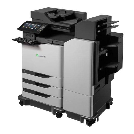
Multiposition staple, hole punch finisher tall configurations 0563‑FNT Caster base 9045‑076 MFP/MSHPF height configuration The MSHPF (multiposition staple, hole punch finisher) can be installed with the CX825 or CX860 model. It has two mailbox bins that can hold 125 sheets each. General information... -
Page 36: Finding The Serial Number
7564 Make sure to observe either of the two device/finisher height configurations: • Short configuration—MFP + two 550‑sheet trays + caster base • Tall configuration—MFP + three 550‑sheet trays or one 2200‑sheet tray + caster base Note: The finisher comes with its own integrated stand for support. Finding the serial number Pull out tray 1, and then find the serial number at the left side of the printer. -
Page 37: Paper And Specialty Media Guide
• For more information on card stock and labels, see the Card Stock & Label Guide at http://support.lexmark.com. Supported paper sizes, types, and weights The following tables provide information on standard and optional paper sources and the sizes, types, and weights of paper they support. - Page 38 7564 Paper size Dimensions 550‑shee 2200‑shee Multipurpose Two‑sided Staple Multipositi t tray t tray printing finisher on hole feeder punch, staple finisher 210 x 297 mm (8.3 x 11.7 in.) Oficio 216 x 340 mm (8.5 x 13.4 in.) 139.7 x 148 mm (5.5 x 5.8 in.) to 215.9 x 359.9 mm (8.5 x 14.2 in.)
-
Page 39: Supported Paper Types
7564 Supported paper types Note: Labels, envelopes, and card stock always print at reduced speed. Paper type 550‑sheet 2200-sheet Multipurpose Two‑sided Staple Multiposi tray tray feeder printing tion finisher staple, hole punch finisher Plain Paper Card Stock Recycled Glossy Heavy Glossy Labels Bond Envelope... -
Page 40: Paper Guidelines
7564 Paper type Standard 550‑sheet 2200-sheet tray Multipurpose feeder tray Card stock Not applicable 88–300 g/m (60– 163–176 g/m (90–120 lb) 192 lb) Labels Not applicable 88–300 g/m (60– 199–220 g/m (53–59 lb) 192 lb) Envelopes Not applicable Not applicable 60–105 g/m (16–28 lb) Paper guidelines... - Page 41 (electrophotographic) printers. While no blanket statement can be made that all recycled paper feeds well, Lexmark consistently tests papers that represent recycled cut size copier papers available on the global market. This scientific testing is conducted with rigor and discipline.
- Page 42 Lexmark concerns itself with the responsible use of paper in general based on life cycle assessments of its products. To gain a better understanding of the impact of printers on the environment, the company commissioned a number of life cycle assessments and found that paper was identified as the primary contributor...
-
Page 43: Using Specialty Media
7564 Storing paper Use these paper storage guidelines to help avoid jams and uneven print quality: • For best results, store paper where the temperature is 21°C (70°F) and the relative humidity is 40 percent. Most label manufacturers recommend printing in a temperature range of 18–24°C (65–75°F) with relative humidity between 40 and 60 percent. - Page 44 Print samples on labels being considered for use before buying large quantities. • For more information on label printing, characteristics, and design, see the Card Stock & Label Guide on the Lexmark Web site at http://support.lexmark.com. • Use labels designed specifically for laser printers.
-
Page 45: Data Security Notice
7564 Data security notice Identifying printer memory • Volatile memory—The printer uses standard random access memory (RAM) to buffer user data temporarily during simple print and copy jobs. • Non-volatile memory—The printer may use two forms of non-volatile memory: EEPROM and NAND (flash memory). - Page 46 7564 • #1 Phillips screwdriver, magnetic • #2 Phillips screwdriver, magnetic • #2 Phillips screwdriver, magnetic short-blade • Torx screwdriver (T20 head) • Needle‑nose pliers • Diagonal side cutters • Spring hook • Feeler gauges • Analog or digital multimeter •...
-
Page 47: Diagnostic Information
7564 Diagnostic information CAUTION—SHOCK HAZARD: To avoid the risk of electrical shock and to prevent damage to the printer, remove the power cord from the electrical outlet and disconnect all connections to any external devices before you connect or disconnect any cable, electronic board, or assembly. CAUTION—POTENTIAL INJURY: The printer weighs 61-84 kg (135-185 lb) and requires three or more trained personnel to lift it safely. -
Page 48: Initial Print Quality Check
7564 • “Ghost images check” on page 54 • “Gray or colored background check” on page 55 • “Horizontal dark lines check” on page 58 • “Light print check” on page 59 • “Mottled print and dots check” on page 62 •... -
Page 49: Blank Or White Pages, Or One Color Missing Check
7564 Blank or white pages, or one color missing check Actions Step 1 Go to step 2. Go to step 3. Remove the transfer belt. Check if the cable shield end of the transfer belt contact is touching the black only retract coupler. Does the transfer belt contact interfere with the BOR coupler? Step 2 Go to step 5. - Page 50 7564 Actions Step 7 Go to step 8. Go to step 7. Enter the Diagnostics menu, and then navigate to: Advanced Print Quality Samples > Advanced Print Quality Samples Check the test page. Is only one color missing? Step 8 Go to step 10.
- Page 51 7564 Actions Step 14 Go to step 15. The problem is solved. Replace the main HVPS. See “Main HVPS removal” on page 661. Does the problem remain? Step 15 Go to step 17. Go to step 16. Check the continuity of the main HVPS cable. Does the cable have continuity? Step 16 Go to step 17.
-
Page 52: Dark Print Check
7564 Actions Step 22 Go to step 23. The problem is solved. Reinstall or replace the printhead wiper actuator rack. Does the problem remain? Step 23 Go to step 24. The problem is solved. Replace the printhead. See “Printhead removal” on page 636. - Page 53 7564 Actions Step 4 Go to step 5. The problem is solved. Perform color alignment adjustment on all colors. See “Color alignment adjust” on page 579. Does the problem remain? Step 5 Go to step 6. The problem is solved. Perform the Toner patch sensing service check.
-
Page 54: Ghost Images Check
7564 Actions Step 13 Go to step 14. The problem is solved. Repair the pins or replace the transfer belt contacts. Does the problem remain? Step 14 Contact the next The problem is level of support. solved. Replace the main HVPS. See “Main HVPS removal”... -
Page 55: Gray Or Colored Background Check
7564 Actions Step 5 Go to step 6. The problem is solved. Replace the transfer belt. See “Transfer belt removal” on page 652. Does the problem remain? Step 6 Contact the next The problem is level of support. solved. Replace the fuser. See “Fuser removal”... - Page 56 7564 Actions Step 4 Go to step 5. Go to step 6. Check the waste toner bottle. Is the waste toner bottle full? Step 5 Go to step 6. The problem is solved. Replace the waste toner bottle. Does the problem remain? Step 6 Go to step 8.
- Page 57 7564 Actions Step 13 Go to step 14. The problem is solved. Replace the cable. Does the problem remain? Step 14 Go to step 16. Go to step 15. Check the charge roller HVPS for proper connection. • Check the charge roller HVPS connector. •...
-
Page 58: Horizontal Dark Lines Check
7564 Actions Step 22 Contact the next The problem is level of support. solved. Replace the controller board. See “Controller board removal” on page 677. Does the problem remain? Horizontal dark lines check ABCDE ABCDE ABCDE Actions Step 1 Go to step 2. Go to step 3. -
Page 59: Light Print Check
7564 Actions Step 6 Contact the next The problem is level of support. solved. Replace the transfer belt. See “Transfer belt removal” on page 652. Does the problem remain? Light print check Actions Step 1 Go to step 2. The problem is solved. - Page 60 7564 Actions Step 5 Go to step 6. Go to step 15. Enter the Diagnostics menu, and then navigate to: Advanced Print Quality Samples > Advanced Print Quality Samples Check the test page. Is only one color producing light print? Step 6 Go to step 8.
- Page 61 7564 Actions Step 12 Go to step 15. Go to step 13. Enter the Diagnostics menu, and then navigate to: Printer diagnostics & adjustments > Motor tests Select the motor (toner add) with the affected color, and then touch Start. Does the motor run? Step 13 Go to step 14.
-
Page 62: Mottled Print And Dots Check
7564 Actions Step 19 Go to step 21. Go to step 20. Check the continuity of the main HVPS cable. Does the cable have continuity? Step 20 Go to step 21. The problem is solved. Replace the cable. Does the problem remain? Step 21 Go to step 23. - Page 63 7564 Actions Step 1 Go to step 3. Go to step 2. From the home screen, touch Settings > Device > Preferences. Check if the paper type and size settings match the paper type and size set on the tray. Do the settings match? Step 2 Go to step 3.
-
Page 64: Print Crooked Or Skewed Check
7564 Actions Step 8 Go to step 9. The problem is solved. Replace the appropriate photoconductor unit or developer unit. “Developer unit and photoconductor unit removal” on page 646. Does the problem remain? Step 9 Go to step 10. Go to step 11. Enter the Diagnostics menu, and then navigate to: Advanced Print Quality Samples >... - Page 65 7564 Actions Step 1 Go to step 2. The problem is solved. Check the positions of the guides on all the trays. Adjust the guides to match the size of the paper. Does the problem remain? Step 2 Go to step 4. Go to step 3.
-
Page 66: Solid Color Or Black Images Check
7564 Solid color or black images check Actions Step 1 Go to step 2. Go to step 4. Enter the Diagnostics menu, and then navigate to: Advanced Print Quality Samples > Advanced Print Quality Samples Check the test page. Is only one color producing the solid color image? Step 2 Go to step 3. -
Page 67: Text Or Images Cut Off Check
7564 Actions Step 7 Go to step 8. The problem is solved. Replace the cable. Does the problem remain? Step 8 Go to step 10. Go to step 9. Check the high voltage connectors on the charge roller HVPS for proper connection. -
Page 68: Toner Easily Rubs Off Check
7564 Toner easily rubs off check Leading edge Trailing edge Actions Step 1 Go to step 2. The problem is solved. From the home screen, touch Settings > Device > Preferences. Make sure that the paper type and size settings match with the paper type and size set on the tray. -
Page 69: Uneven Print Density Check
7564 Actions Step 8 Contact the next The problem is level of support. solved. Replace the LVPS. See “LVPS removal” on page 679. Does the problem remain? Uneven print density check Actions Step 1 Go to step 2. The problem is solved. -
Page 70: Vertical Dark Lines Or Streaks Check
7564 Actions Step 5 Go to step 6. The problem is solved. Remove, and then reinstall the transfer roller. See “Transfer roller removal” on page 607. Does the problem remain? Step 6 Go to step 7. The problem is solved. Replace the transfer belt. -
Page 71: Vertical White Lines Or Voids Check
7564 Actions Step 4 Contact the next The problem is level of support. solved. Replace the fuser. See “Fuser removal” on page 606. Does the problem remain? Vertical white lines or voids check Leading edge Trailing edge Actions Step 1 Go to step 2. -
Page 72: Blurred Print Or Misaligned Color Check
7564 Actions Step 5 Contact the next The problem is level of support. solved. Replace the printhead. See “Printhead removal” on page 636. Does the problem remain? Blurred print or misaligned color check Actions Step 1 Go to step 2. Go to step 3. -
Page 73: Image Banding Check
7564 Actions Step 6 Go to step 7. The problem is solved. Turn off the printer to let the printhead shutters remain open. Remove the developer and PC unit combos, and then clean the printhead lenses using a lint‑free cloth. Does the problem remain? Step 7 Go to step 8. - Page 74 7564 Actions Step 4 Go to step 5. The problem is solved. Remove, and then reinstall the transfer roller. See “Transfer roller removal” on page 607. Does the problem remain? Step 5 Go to step 6. The problem is solved. Remove, and then reinstall the transfer belt.
-
Page 75: Image Void (Process Direction) Check
7564 Image void (process direction) check Actions Step 1 Go to step 2. The problem is solved. Load paper from a fresh package. Note: Paper may absorb moisture due to high humidity. Store paper in its original wrapper until it is ready to be used. Does the problem remain? Step 2 Go to step 3. -
Page 76: Random Marks Check
7564 Actions Step 8 Go to step 9. Go to step 10. Enter the Diagnostics menu, and then navigate to: Advanced Print Quality Samples > Advanced Print Quality Samples Check the test page. Is only one color affected? Step 9 Go to step 10. -
Page 77: Repeating Defects Check
7564 Actions Step 3 Go to step 5. Go to step 4. Check the developer and PC unit combo for contamination. Is the developer and PC unit combo free of contamination? Step 4 Go to step 5. The problem is solved. - Page 78 7564 Action Step 4 Contact the next The problem is level of support. solved. Do the following: • If the affected color is cyan, magenta, or yellow, then replace the appropriate developer unit. • If the affected color is black, then replace the black developer unit.
-
Page 79: Fixing Scan Quality Issues
7564 Action Step 11 Go to step 13. Go to step 12. Measure the distance between the repeating marks. Is the distance between the marks either 47.1 mm or 90 mm? Step 12 Go to step 13. Contact the next level of support. - Page 80 7564 Actions Step 5 Go to step 7. Go to step 6. Check the white and black reference strips on the bottom of the ADF float plate for contamination. Are the reference strips free of contamination? Step 6 Go to step 7. The problem is solved.
-
Page 81: Vertical Lines (Process Direction Using The Adf) Check
7564 Vertical lines (process direction using the ADF) check Actions Step 1 Go to step 2. Go to step 3. Isolate the scanner system by printing the advanced print quality samples directly from the printer. Enter the Diagnostics menu, and then navigate to: Advanced Print Quality Samples >... -
Page 82: Spots (Using The Flatbed Scanner) Check
7564 Spots (using the flatbed scanner) check Actions Step 1 Go to step 2. Go to step 3. Isolate the scanner system by printing the advanced print quality samples directly from the printer. Enter the Diagnostics menu, and then navigate to: Advanced Print Quality Samples >... -
Page 83: Adf Skew Check
7564 ADF skew check Actions Step 1 Go to step 2. Go to step 3. Isolate the scanner system by printing the advanced print quality samples directly from the printer. Enter the Diagnostics menu, and then navigate to: Advanced Print Quality Samples > Advanced Print Quality Samples Is the scan defect seen on the print quality samples? Step 2... -
Page 84: Media Damage (Using The Adf) Check
7564 Actions Step 9 Go to step 11. Go to step 10. Check the ADF pick roller assembly for wear or damage. Is the assembly free of wear or damage? Step 10 Go to step 11. The problem is solved. Replace the ADF pick roller assembly. -
Page 85: Wavy Edge (Adf 2Nd Side Scan) Service Check
7564 Actions Step 4 Go to step 5. The problem is solved. Clear the paper path in the ADF of any obstructions. Does the problem remain? Step 5 Go to step 6. The problem is solved. Open, and then properly close the following ADF covers and door: •... - Page 86 7564 Actions Step 1 Go to step 3. Go to step 2. Raise the ADF to its full upright position. Check the plastic locaters (A) on the rear of the CCDM (ADF). Note: The locaters are properly seated in the slot (B) if there is no gap (C) between the metal plate and the frame rib.
-
Page 87: Paper Jams
7564 Paper jams Avoiding jams Load paper properly • Make sure that the paper lies flat in the tray. Correct loading of paper Incorrect loading of paper • Do not load or remove a tray while the printer is printing. •... -
Page 88: Identifying Jam Locations
7564 • Flex, fan, and align the paper edges before loading. • Do not use paper that has been cut or trimmed by hand. • Do not mix paper sizes, weights, or types in the same tray. • Make sure that the paper size and type are set correctly on the computer or printer control panel. •... - Page 89 7564 Jam locations Automatic document feeder (ADF) Standard bin Door G Door F Trays Configured model Jam locations Door L Door J Door K Door N Diagnostic information...
-
Page 90: Paper Jam In Trays
7564 Paper jam in trays Pull out the tray. Remove the jammed paper. Note: Make sure that all paper fragments are removed. Insert the tray. Open the tray cover. Diagnostic information... -
Page 91: Paper Jam In The Multipurpose Feeder
7564 Remove the jammed paper. Note: Make sure that all paper fragments are removed. Close the tray cover. Paper jam in the multipurpose feeder Remove paper from the multipurpose feeder. Remove the jammed paper. Note: Make sure that all paper fragments are removed. Open door B, and then remove any paper fragments. -
Page 92: Paper Jam In The Automatic Document Feeder
7564 Close door B. Flex, fan, and align the paper edges before loading. Reload paper. Paper jam in the automatic document feeder Remove all original documents from the ADF tray. Open door D. Remove the jammed paper. Note: Make sure that all paper fragments are removed. Diagnostic information... - Page 93 7564 Warning—Potential Damage: Some parts of the printer are easily damaged by static electricity. Before touching any parts or components in an area marked with the static‑sensitive symbol, touch a metal surface in an area away from the symbol. Close door D. Open the scanner cover.
-
Page 94: Paper Jam In The Standard Bin
7564 Open door E. Remove the jammed paper. Note: Make sure that all paper fragments are removed. Close door E and the scanner cover. Paper jam in the standard bin Remove the jammed paper. Note: Make sure that all paper fragments are removed. Diagnostic information... -
Page 95: Paper Jam In Door B
7564 Open door B, and then remove any paper fragments. CAUTION—HOT SURFACE: The inside of the printer might be hot. To reduce the risk of injury from a hot component, allow the surface to cool before touching it. Close door B. Paper jam in door B Paper jam in the fuser Open door B. - Page 96 7564 Remove the jammed paper. Note: Make sure that all paper fragments are removed. Diagnostic information...
- Page 97 7564 Open the fuser access door. Remove the jammed paper. Note: Make sure that all paper fragments are removed. Close door B. Paper jam in the duplex unit Open door B. CAUTION—HOT SURFACE: The inside of the printer might be hot. To reduce the risk of injury from a hot component, allow the surface to cool before touching it.
- Page 98 7564 Remove the jammed paper. Note: Make sure that all paper fragments are removed. Open the duplex cover. Remove the jammed paper. Note: Make sure that all paper fragments are removed. Diagnostic information...
-
Page 99: Paper Jam In The Finisher Bin
7564 Close the duplex cover and door B. Paper jam in the finisher bin Remove the jammed paper. Note: Make sure that all paper fragments are removed. Open door C. Diagnostic information... - Page 100 7564 Open door F. Remove the jammed paper. Note: Make sure that all paper fragments are removed. Close doors F and C. CAUTION—PINCH HAZARD: To avoid the risk of a pinch injury, keep hands clear of the labeled area when closing door C. Diagnostic information...
-
Page 101: Staple Jam In Door G
7564 Staple jam in door G Open door C. Open door G. Diagnostic information... - Page 102 7564 Pull out the staple cartridge holder. Lift the staple guard, remove the loose staples, and then remove the partial slab of staples so only the full slabs remain. Diagnostic information...
- Page 103 7564 Close the staple guard. Diagnostic information...
-
Page 104: Paper Jam In Door K
7564 Insert the staple cartridge holder. Close doors G and C. CAUTION—PINCH HAZARD: To avoid the risk of a pinch injury, keep hands clear of the labeled area when closing door C. Paper jam in door K Open doors C and K. Remove the jammed paper. -
Page 105: Paper Jam In Door J
7564 • Using knob J2 Close doors K and C. CAUTION—PINCH HAZARD: To avoid the risk of a pinch injury, keep hands clear of the labeled area when closing door C. Paper jam in door J Open door J. Remove the jammed paper. Note: Make sure that all paper fragments are removed. - Page 106 7564 • Area J1 • Areas J3 and J4 • Areas J5 and J6 Close door J. Diagnostic information...
-
Page 107: Paper Jam In Door N
7564 Paper jam in door N Open door N. Remove the jammed paper. Note: Make sure that all paper fragments are removed. Close door N. Diagnostic information... -
Page 108: Paper Jam In Door L
7564 Paper jam in door L Open door L. Remove the jammed paper. Note: Make sure that all paper fragments are removed. Close door L. Diagnostic information... -
Page 109: Paper Jam In The Staple Finisher Bin
7564 Paper jam in the staple finisher bin Open door J. Remove the jammed paper. Note: Make sure that all paper fragments are removed. Close door J. Staple jam in door J Open door J. Diagnostic information... - Page 110 7564 Remove the staple cartridge holder. Open the staple guard, and then remove the loose staples. Note: Do not insert the staples that came out of the cartridge. Diagnostic information...
-
Page 111: Paper Jams
7564 Close the staple guard. Insert the staple cartridge holder. Close door J. 200 paper jams 200 paper jam messages Error code Description Action 200.02 Paper fed from the MPF was detected earlier than “Sensor (input): Paper arrived too early expected at the sensor (input). - Page 112 7564 Error code Description Action 200.15 Paper fed from tray 1 never cleared the sensor “Sensor (input): Paper failed to clear (input). service check” on page 114. 200.16 Paper fed from tray 1 was picked but it never “Sensor (input): Tray 1 failed to pick service arrived at the sensor (input).
- Page 113 7564 Error code Description Action 200.55 Paper fed from tray 5 never cleared the sensor “Sensor (input): Paper failed to clear (input). service check” on page 114. 200.56 Paper fed from tray 5 was picked but it never “Sensor (input): Paper (tray 5) failed to arrived at the sensor (input).
- Page 114 7564 Sensor (input): Paper failed to clear service check Action Step 1 Go to step 3. Go to step 2. Check if the paper size matches the size set on the tray guides. Does the paper size match the size set on the tray? Step 2 Go to step 3.
- Page 115 7564 Action Step 10 Go to step 13. Go to step 11. Enter the Diagnostics menu, and then navigate to: Printer diagnostics & adjustments > Motor tests > Isolation Touch Start. Does the motor run? Step 11 Go to step 12. The problem is solved.
- Page 116 7564 Action Step 5 Go to step 6. Go to step 7. Check the paper condition in the tray. Is the paper crumpled or damaged? Step 6 Go to step 7. The problem is solved. Replace the crumpled or damaged paper. Does the problem remain? Step 7 Go to step 9.
- Page 117 7564 Action Step 14 Go to step 15. The problem is solved. Clean the paper path. Does the problem remain? Step 15 Go to step 18. Go to step 16. Enter the Diagnostics menu, and then navigate to: Printer diagnostics & adjustments > Sensor tests Find the sensor (Input).
- Page 118 7564 Action Step 22 Contact the next The problem is level of support. solved. Replace the tray 1 paper feeder. See “Paper feeder removal” on page 665. Does the problem remain? Sensor (input): Paper (tray 2) failed to arrive service check Action Step 1 Go to step 3.
- Page 119 7564 Action Step 9 Go to step 11. Go to step 10. Check the condition of the tray 2 pick roller. Is the pick roller free from excess wear, contamination, and damage? Step 10 Go to step 11. The problem is solved.
- Page 120 7564 Action Step 18 Go to step 21. Go to step 19. Enter the Diagnostics menu, and then navigate to: Printer diagnostics & adjustments > Sensor tests Find the sensor (MPF/pass-through). Does the sensor status change while toggling the sensor? Step 19 Go to step 20.
- Page 121 7564 Sensor (input): Paper (tray 3) failed to arrive service check Action Step 1 Go to step 3. Go to step 2. Check the tray 1 paper path. Is the paper path free of fragments and contamination? Step 2 Go to step 3. The problem is solved.
- Page 122 7564 Action Step 11 Go to step 13. Go to step 12. Check the condition of the tray 3 pick roller. Is the pick roller free from excess wear, contamination, and damage? Step 12 Go to step 13. The problem is solved.
- Page 123 7564 Action Step 20 Go to step 23. Go to step 21. Enter the Diagnostics menu, and then navigate to: Printer diagnostics & adjustments > Sensor tests Find the sensor (MPF/pass through). Does the sensor status change while toggling the sensor? Step 21 Go to step 22.
- Page 124 7564 Sensor (input): Paper (tray 4) failed to arrive service check Action Step 1 Go to step 3. Go to step 2. Check the tray 1 paper path. Is the paper path free of fragments and contamination? Step 2 Go to step 3. The problem is solved.
- Page 125 7564 Action Step 11 Go to step 13. Go to step 12. Check the tray 4 separator pad for misalignment and damage. Is the separator pad properly installed and free of damage? Step 12 Go to step 13. The problem is solved.
- Page 126 7564 Action Step 20 Go to step 21. The problem is solved. Check the sensor cable for proper connection, and then reseat if necessary. Does the problem remain? Step 21 Go to step 22. The problem is solved. Replace the sensor. See “Sensor (input) removal”...
- Page 127 7564 Action Step 28 Go to step 31. Go to step 29. Enter the Diagnostics menu, and then navigate to: Additional input tray diagnostics > Sensor tests Find the sensor (Pass-through (tray 3)). Does the sensor status change while toggling the sensor? Step 29 Go to step 30.
- Page 128 7564 Action Step 36 Go to step 37. The problem is solved. Replace the motor. See “Motor (550-sheet tray pass‑through) removal” on page 762. Does the problem remain? Step 37 Go to step 40. Go to step 38. Enter the Diagnostics menu, and then navigate to: Additional input tray diagnostics >...
- Page 129 7564 Action Step 4 Go to step 5. The problem is solved. Clean the paper path. Does the problem remain? Step 5 Go to step 7. Go to step 6. Check the tray 3 paper path. Is the paper path free of fragments and contamination? Step 6 Go to step 7.
- Page 130 7564 Action Step 14 Go to step 15. The problem is solved. Reinstall or replace the separator pad. See “Separator pad removal” on page 655. Does the problem remain? Step 15 Go to step 17. Go to step 16. Check the condition of the tray 5 pick roller. Is the pick roller free from excess wear, contamination, and damage? Step 16...
- Page 131 7564 Action Step 23 Go to step 24. The problem is solved. Replace the sensor. See “Sensor (input) removal” on page 621. Does the problem remain? Step 24 Go to step 27. Go to step 25. Enter the Diagnostics menu, and then navigate to: Printer diagnostics &...
- Page 132 7564 Action Step 31 Go to step 32. The problem is solved. Check the sensor cable for proper connection, and then reseat if necessary. Does the problem remain? Step 32 Go to step 33. The problem is solved. Replace the sensor. Does the problem remain? Step 33 Go to step 36.
- Page 133 7564 Action Step 39 Go to step 42. Go to step 40. Enter the Diagnostics menu, and then navigate to: Additional input tray diagnostics > Motor tests > Pass- through (tray 2) Touch Start. Does the motor run? Step 40 Go to step 41.
- Page 134 7564 Action Step 46 Go to step 47. The problem is solved. Check the motor cable for proper connection, and then reseat if necessary. Does the problem remain? Step 47 Go to step 48. The problem is solved. Replace the motor. See “Motor (550-sheet tray pass‑through) removal”...
- Page 135 7564 Action Step 7 Go to step 9. The problem is solved. Enter the Diagnostics menu, and then navigate to: Printer diagnostics & adjustments > Sensor tests Find the sensor (Input). Does the sensor status change while toggling the sensor? Step 8 Go to step 9.
-
Page 136: Paper Jams
7564 Action Step 5 Go to step 6. The problem is solved. Replace the sensor. See “Sensor (input) removal” on page 621. Does the problem remain? Step 6 Contact the next The problem is level of support. solved. Perform a print job. Does the problem remain? 201–202 paper jams 201–202 paper jam messages... - Page 137 7564 Error Description Action code 202.23 Paper fed from tray 2 never arrived at the “Sensor (fuser exit): Paper failed to arrive service sensor (fuser exit). check” on page 139. 202.24 Paper fed from tray 2 cleared the sensor “Sensor (fuser exit): Paper cleared too early service (fuser exit) earlier than expected.
- Page 138 7564 Sensor (fuser buckle) static jam service check Action Step 1 Go to step 3. Go to step 2. Check the paper path for partially fed or jammed paper. Is the paper path free of partially fed or jammed paper? Step 2 Go to step 3.
- Page 139 7564 Action Step 3 Go to step 5. Go to step 4. Check the fuser rollers for damage. Are the rollers free of damage? Step 4 Go to step 5. The problem is solved. Replace the fuser. See “Fuser removal” on page 606.
- Page 140 7564 Action Step 7 Go to step 10. Go to step 8. Enter the Diagnostics menu, and then navigate to: Printer diagnostics & adjustments > Sensor tests Find the sensor (Fuser exit). Does the sensor status change while toggling the sensor? Step 8 Go to step 9.
- Page 141 7564 Action Step 15 Go to step 18. Go to step 16. Enter the Diagnostics menu, and then navigate to: Printer diagnostics & adjustments > Motor tests > Transfer belt Touch Start. Does the motor run? Step 16 Go to step 17. The problem is solved.
- Page 142 7564 Action Step 5 Go to step 6. The problem is solved. Replace the fuser. See “Fuser removal” on page 606. Does the problem remain? Step 6 Contact the next The problem is level of support. solved. Perform a print job. Does the problem remain? Sensor (fuser exit): Paper failed to clear service check Action...
- Page 143 7564 Action Step 8 Go to step 9. The problem is solved. Check the sensor cable for proper connection, and then reseat if necessary. Does the problem remain? Step 9 Go to step 10. The problem is solved. Replace the fuser. See “Fuser removal”...
-
Page 144: Paper Jams
7564 Sensor (fuser exit) static jam service check Action Step 1 Go to step 3. Go to step 2. Check the paper path for partially fed or jammed paper. Is the paper path free of partially fed or jammed paper? Step 2 Go to step 3. - Page 145 7564 Error Description Action code 212.05 Paper fed from the MPF never cleared the “Sensor (deskew roller entry): Paper failed to clear sensor (deskew roller entry). service check” on page 149. 212.07 Paper fed from the MPF never cleared the sensor (deskew roller entry).
- Page 146 7564 Error Description Action code 212.42 Paper fed from tray 4 was detected earlier “Sensor (deskew roller entry): Paper arrived too early than expected at the sensor (deskew service check” on page 146. roller entry). 212.43 Paper fed from tray 4 never arrived at the “Sensor (deskew roller entry): Paper failed to arrive sensor (deskew roller entry).
- Page 147 7564 Action Step 3 Go to step 5. Go to step 4. Check the deskew roller for damage. Is the roller free of damage? Step 4 Go to step 5. The problem is solved. Replace the deskew roller. Does the problem remain? Step 5 Contact the next The problem is...
- Page 148 7564 Action Step 6 Go to step 7. The problem is solved. Check the sensor cable for proper connection, and then reseat if necessary. Does the problem remain? Step 7 Go to step 8. The problem is solved. Replace the sensor. Does the problem remain? Step 8 Go to step 11.
- Page 149 7564 Action Step 3 Go to step 6. Go to step 4. Enter the Diagnostics menu, and then navigate to: Printer diagnostics & adjustments > Sensor tests Find the sensor (Deskew roller entry). Does the sensor status change while toggling the sensor? Step 4 Go to step 5.
- Page 150 7564 Action Step 5 Go to step 8. Go to step 6. Enter the Diagnostics menu, and then navigate to: Printer diagnostics & adjustments > Sensor tests Find the sensor (Deskew roller entry). Does the sensor status change while toggling the sensor? Step 6 Go to step 7.
-
Page 151: Paper Jams
7564 Sensor (deskew roller entry) static jam service check Action Step 1 Go to step 3. Go to step 2. Check the paper path for paper jams and fragments. Is the paper path free of jams and fragments? Step 2 Go to step 3. - Page 152 7564 Error Description Action code 213.05 Paper fed from the MPF never cleared the “Sensor (deskew roller exit): Paper failed to clear sensor (deskew roller exit). service check” on page 156. 213.07 Paper fed from the MPF never cleared the sensor (deskew roller exit).
- Page 153 7564 Error Description Action code 213.44 Paper fed from tray 4 cleared the sensor “Sensor (deskew roller exit): Paper cleared too early (deskew roller exit) earlier than expected. service check” on page 155. 213.45 Paper fed from tray 4 never cleared the “Sensor (deskew roller exit): Paper failed to clear sensor (deskew roller exit).
- Page 154 7564 Action Step 5 Contact the next The problem is level of support. solved. Perform a print job. Does the problem remain? Sensor (deskew roller exit): Paper failed to arrive service check Action Step 1 Go to step 3. Go to step 2. Check the paper path for paper jams and fragments.
- Page 155 7564 Action Step 8 Go to step 11. Go to step 9. Enter the Diagnostics menu, and then navigate to: Printer diagnostics & adjustments > Motor tests > Deskew Touch Start. Does the motor run? Step 9 Go to step 10. The problem is solved.
- Page 156 7564 Action Step 5 Go to step 6. The problem is solved. Replace the sensor (deskew roller exit). Does the problem remain? Step 6 Contact the next The problem is level of support. solved. Perform a print job. Does the problem remain? Sensor (deskew roller exit): Paper failed to clear service check Action Step 1...
- Page 157 7564 Action Step 7 Go to step 8. The problem is solved. Check the motor cable for proper connection, and then reseat if necessary. Does the problem remain? Step 8 Go to step 9. The problem is solved. Replace the motor. Does the problem remain? Step 9 Contact the next...
-
Page 158: Paper Jams
7564 Action Step 6 Go to step 7. The problem is solved. Clean or replace the deskew roller. Does the problem remain? Step 7 Go to step 8. The problem is solved. Replace the sensor (deskew roller exit). Does the problem remain? Step 8 Contact the next The problem is... - Page 159 7564 Error Description Action code 230.22 Paper fed from tray 2 was detected earlier “Sensor (duplex path 1): Paper arrived too early than expected at the sensor (duplex path service check” on page 160. 230.23 Paper fed from tray 2 never arrived at the “Sensor (duplex path 1): Paper failed to arrive service sensor (duplex path 1).
- Page 160 7564 Sensor (redrive buckle) static jam service check Action Step 1 Go to step 3. Go to step 2. Check the paper path for partially fed or jammed paper. Is the paper path free of partially fed or jammed paper? Step 2 Go to step 3.
- Page 161 7564 Action Step 3 Contact the next The problem is level of support. solved. Perform a print job. Does the problem remain? Sensor (duplex path 1): Paper failed to arrive service check Action Step 1 Go to step 3. Go to step 2. Check the redrive area for paper jams and fragments.
- Page 162 7564 Action Step 8 Go to step 11. Go to step 9. Enter the Diagnostics menu, and then navigate to: Printer diagnostics & adjustments > Motor tests > Duplex diverter Touch Start. Does the motor run? Step 9 Go to step 10. The problem is solved.
- Page 163 7564 Action Step 16 Go to step 17. The problem is solved. Replace the motor. Does the problem remain? Step 17 Go to step 19. Go to step 18. Check the duplex drive gears for damage. Is the duplex drive gears free of damage? Step 18 Go to step 19.
- Page 164 7564 Action Step 3 Go to step 6. Go to step 4. Enter the Diagnostics menu, and then navigate to: Printer diagnostics & adjustments > Sensor tests Find the sensor (Duplex path 1). Does the sensor status change while toggling the sensor? Step 4 Go to step 5.
- Page 165 7564 Action Step 5 Go to step 7. Go to step 6. Check the duplex path for paper jams and fragments. Is the paper path free of jams and fragments? Step 6 Go to step 7. The problem is solved. Remove the paper jams and fragments.
-
Page 166: Paper Jams
7564 Sensor (duplex path 1) static jam service check Action Step 1 Go to step 3. Go to step 2. Check the paper path for paper jams and fragments. Is the paper path free of jams and fragments? Step 2 Go to step 3. - Page 167 7564 Error Description Action code 231.05 Paper fed from the MPF never cleared the “Sensor (duplex path 2): Paper failed to clear service sensor (duplex path 2). check” on page 171. 231.12 Paper fed from tray 1 was detected earlier “Sensor (duplex path 2): Paper arrived too early than expected at the sensor (duplex path service check”...
- Page 168 7564 Error Description Action code 231.53 Paper fed from tray 5 never arrived at the “Sensor (duplex path 2): Paper failed to arrive service sensor (duplex path 2). check” on page 168. 231.54 Paper fed from tray 5 cleared the sensor “Sensor (duplex path 2): Paper cleared too early (duplex path 2) earlier than expected.
- Page 169 7564 Action Step 3 Go to step 6. Go to step 4. Enter the Diagnostics menu, and then navigate to: Printer diagnostics & adjustments > Sensor tests Find the sensor (Duplex path 2). Does the sensor status change while toggling the sensor? Step 4 Go to step 5.
- Page 170 7564 Action Step 12 Go to step 13. The problem is solved. Replace the duplex assembly. Does the problem remain? Step 13 Contact the next The problem is level of support. solved. Perform a print job. Does the problem remain? Sensor (duplex path 2): Paper cleared too early service check Action Step 1...
- Page 171 7564 Sensor (duplex path 2): Paper failed to clear service check Action Step 1 Go to step 3. Go to step 2. Check if the paper size matches the size set on the tray guides. Does the paper size match the size set on the tray? Step 2 Go to step 3.
- Page 172 7564 Action Step 9 Go to step 10. The problem is solved. Check the motor cable for proper connection, and then reseat if necessary. Does the problem remain? Step 10 Go to step 11. The problem is solved. Replace the motor. Does the problem remain? Step 11 Contact the next...
-
Page 173: Paper Jams
7564 Action Step 6 Contact the next The problem is level of support. solved. Perform a print job. Does the problem remain? 232 paper jams 232 paper jam messages Error Description Action code 232.03 Paper fed from the MPF never arrived at “Sensor (input): Paper (duplex job) failed to arrive the sensor (input) during a duplex print service check”... - Page 174 7564 Error Description Action code 232.34 Paper fed from tray 3 cleared the sensor “Sensor (input): Paper (duplex job) cleared too early (input) earlier than expected during a service check” on page 176. duplex print job. 232.35 Paper fed from tray 3 never cleared the “Sensor (input): Paper (duplex job) failed to clear sensor (input) during a duplex print job.
- Page 175 7564 Action Step 4 Go to step 5. The problem is solved. Remove the paper jams and fragments. Does the problem remain? Step 5 Go to step 8. Go to step 6. Enter the Diagnostics menu, and then navigate to: Printer diagnostics &...
- Page 176 7564 Action Step 13 Go to step 15. Go to step 14. Check the duplex assembly for damaged gears, belts, and rollers. Is the duplex assembly free of damage? Step 14 Go to step 15. The problem is solved. Replace the duplex assembly. Does the problem remain? Step 15 Contact the next...
- Page 177 7564 Action Step 6 Contact the next The problem is level of support. solved. Perform a print job. Does the problem remain? Sensor (input): Paper (duplex job) failed to clear service check Action Step 1 Go to step 3. Go to step 2. Check if the paper size matches the size set on the tray guides.
-
Page 178: Paper Jams
7564 Action Step 8 Go to step 11. Go to step 9. Enter the Diagnostics menu, and then navigate to: Printer diagnostics & adjustments > Motor tests > Deskew Touch Start. Does the motor run? Step 9 Go to step 10. The problem is solved. - Page 179 7564 Error Description Action code 240.33 Paper fed from tray 3 was picked but it “Sensor (MPF/pass-through): Paper (tray 3) failed to never arrived at the sensor (MPF/pass- arrive service check” on page 179. through). 240.35 Paper fed from tray 3 cleared the sensor “Sensor (MPF/pass‑through): Paper failed to clear (MPF/pass-through) later than expected.
- Page 180 7564 Action Step 4 Go to step 5. The problem is solved. Replace the crumpled or damaged paper. Does the problem remain? Step 5 Go to step 8. Go to step 6. Enter the Diagnostics menu, and then navigate to: Printer diagnostics &...
- Page 181 7564 Action Step 12 Go to step 13. The problem is solved. Check the motor cable for proper connection, and then reseat if necessary. Does the problem remain? Step 13 Go to step 14. The problem is solved. Replace the motor. See “Motor (550-sheet tray pass‑through) removal”...
- Page 182 7564 Action Step 6 Go to step 7. The problem is solved. Check the sensor cable for proper connection, and then reseat if necessary. Does the problem remain? Step 7 Go to step 8. The problem is solved. Replace the sensor. See “Sensor (MPF/pass-through) with deflector removal”...
- Page 183 7564 Action Step 14 Go to step 17. Go to step 15. Enter the Diagnostics menu, and then navigate to: Additional input tray diagnostics > Motor tests > Pass- through (tray 2) Touch Start. Does the motor run? Step 15 Go to step 16.
- Page 184 7564 Sensor (MPF/pass‑through): Paper (tray 5) failed to arrive service check Action Step 1 Go to step 3. Go to step 2. Check the tray 2 paper path guides for paper jams and fragments. Is the paper path free of jams and fragments? Step 2 Go to step 3.
- Page 185 7564 Action Step 10 Go to step 13. Go to step 11. Enter the Diagnostics menu, and then navigate to: Additional input tray diagnostics > Sensor tests Find the sensor (Pass-through (tray 2)). Does the sensor status change while toggling the sensor? Step 11 Go to step 12.
- Page 186 7564 Action Step 18 Go to step 19. The problem is solved. Replace the sensor. Does the problem remain? Step 19 Go to step 22. Go to step 20. Enter the Diagnostics menu, and then navigate to: Additional input tray diagnostics > Motor tests > Pass- through (tray 2) Touch Start.
- Page 187 7564 Action Step 25 Go to step 28. Go to step 26. Enter the Diagnostics menu, and then navigate to: Additional input tray diagnostics > Motor tests > Pass- through (tray 4) Touch Start. Does the motor run? Step 26 Go to step 27.
- Page 188 7564 Action Step 5 Go to step 8. Go to step 6. Enter the Diagnostics menu, and then navigate to: Printer diagnostics & adjustments > Sensor tests Find the sensor (MPF/pass-through). Does the sensor status change while toggling the sensor? Step 6 Go to step 7.
- Page 189 7564 MPF failed to pick service check Action Step 1 Go to step 3. Go to step 2. Check if the paper size matches the size set on the tray guides. Does the paper size match the size set on the tray? Step 2 Go to step 3.
- Page 190 7564 Action Step 10 Go to step 11. The problem is solved. Clean the paper path. Does the problem remain? Step 11 Go to step 14. Go to step 12. Enter the Diagnostics menu, and then navigate to: Printer diagnostics & adjustments > Sensor tests Find the sensor (MPF/pass-through).
- Page 191 7564 Sensor (MPF/pass‑through): Tray 2 failed to pick service check Action Step 1 Go to step 3. Go to step 2. Check if the paper size matches the size set on the tray 2 guides. Does the paper size match the size set on the tray? Step 2 Go to step 3.
- Page 192 7564 Action Step 10 Go to step 11. The problem is solved. Replace the pick roller. See “Pick roller removal” on page 654. Does the problem remain? Step 11 Go to step 13. Go to step 12. Check the paper path along the tray 2 exit. Is the paper path free of fragments and contamination? Step 12 Go to step 13.
- Page 193 7564 Action Step 19 Go to step 20. The problem is solved. Perform a print job. Does the problem remain? Step 20 Contact the next The problem is level of support. solved. Replace the tray 2 paper feeder. See “550-sheet tray paper feeder removal”...
- Page 194 7564 Action Step 7 Go to step 10. Go to step 8. Enter the Diagnostics menu, and then navigate to: Printer diagnostics & adjustments > Motor tests > MPF pick Touch Start. Does the motor run? Step 8 Go to step 9. The problem is solved.
-
Page 195: Paper Jams
7564 Action Step 5 Go to step 6. The problem is solved. Replace the sensor. See “Sensor (MPF/pass-through) with deflector removal” on page 622. Does the problem remain? Step 6 Contact the next The problem is level of support. solved. Perform a print job. -
Page 196: Paper Jams
7564 Action Step 6 Go to step 7. The problem is solved. Clean the paper path. Does the problem remain? Step 7 Go to step 10. Go to step 8. Enter the Diagnostics menu, and then navigate to: Printer diagnostics & adjustments > Motor tests > Pick (tray Touch Start. - Page 197 7564 Error Description Action code 242.36 Paper fed from tray 3 was picked but it “Sensor (tray 2 pass‑through): Tray 3 failed to pick never arrived at the sensor (tray 2 pass- service check” on page 203. through). 242.37 Paper fed from tray 3 never cleared the “Sensor (tray 2 pass‑through): Paper failed to clear sensor (tray 2 pass-through).
- Page 198 7564 Error Description Action code 242.92 Paper was detected earlier than expected “Sensor (tray 2 pass-through): Paper arrived too early at the sensor (tray 2 pass-through). Paper service check” on page 198. source is undetermined. 242.93 Paper never arrived at the sensor (tray 2 “Sensor (tray 2 pass‑through): Paper failed to arrive pass-through).
- Page 199 7564 Action Step 6 Contact the next The problem is level of support. solved. Perform a print job. Does the problem remain? Sensor (tray 2 pass‑through): Paper failed to arrive service check Action Step 1 Go to step 3. Go to step 2. Check the tray 3 paper path guides for paper jams and fragments.
- Page 200 7564 Action Step 8 Go to step 9. The problem is solved. Replace the sensor. Does the problem remain? Step 9 Go to step 12. Go to step 10. Enter the Diagnostics menu, and then navigate to: Additional input tray diagnostics > Motor tests > Pass- through (tray 3) Touch Start.
- Page 201 7564 Action Step 4 Go to step 5. The problem is solved. Remove the excess paper from the tray. Does the problem remain? Step 5 Go to step 6. Go to step 7. Check the paper condition in the source tray. Is the paper crumpled or damaged? Step 6 Go to step 7.
- Page 202 7564 Sensor (tray 2 pass‑through): Paper failed to clear service check Action Step 1 Go to step 3. Go to step 2. Check if the paper size matches the size set on the source tray guides. Does the paper size match the size set on the tray? Step 2 Go to step 3.
- Page 203 7564 Action Step 9 Go to step 10. The problem is solved. Check the motor cable for proper connection, and then reseat if necessary. Does the problem remain? Step 10 Go to step 11. The problem is solved. Replace the motor. See “Motor (550-sheet tray pass‑through) removal”...
- Page 204 7564 Action Step 7 Go to step 9. Go to step 8. Check the tray 3 separator pad for misalignment and damage. Is the separator pad properly installed and free of damage? Step 8 Go to step 9. The problem is solved.
- Page 205 7564 Action Step 16 Go to step 19. Go to step 17. Enter the Diagnostics menu, and then navigate to: Additional input tray diagnostics > Motor tests > Pass- through (tray 3) Touch Start. Does the motor run? Step 17 Go to step 18.
- Page 206 7564 Action Step 4 Go to step 5. The problem is solved. Replace the crumpled or damaged paper. Does the problem remain? Step 5 Go to step 7. Go to step 6. Check the paper path along the tray 2 exit. Is the paper path free of fragments and contamination? Step 6 Go to step 7.
-
Page 207: Paper Jams
7564 Sensor (tray 2 pass‑through) static jam service check Action Step 1 Go to step 3. Go to step 2. Check the paper path for paper jams and fragments. Is the paper path free of jams and fragments? Step 2 Go to step 3. - Page 208 7564 Error Description Action code 243.44 Paper fed from tray 4 cleared the sensor “Sensor (tray 3 pass-through): Paper cleared too early (tray 3 pass-through) earlier than service check” on page 213. expected. 243.45 Paper fed from tray 4 never cleared the “Sensor (tray 3 pass‑through): Paper failed to clear sensor (tray 3 pass-through).
- Page 209 7564 Error Description Action code 243.96 Paper was picked but it never arrived at “Sensor (tray 3 pass‑through): Tray 4 failed to pick the sensor (tray 3 pass-through). Paper service check” on page 211. source is undetermined. Sensor (tray 3 pass‑through): Paper arrived too early service check Action Step 1 Go to step 3.
- Page 210 7564 Sensor (tray 3 pass‑through): Paper failed to arrive service check Action Step 1 Go to step 3. Go to step 2. Check the tray paper path guides for paper jams and fragments. Is the paper path free of jams and fragments? Step 2 Go to step 3.
- Page 211 7564 Action Step 9 Contact the next The problem is level of support. solved. Perform a print job. Does the problem remain? Sensor (tray 3 pass‑through): Tray 4 failed to pick service check Action Step 1 Go to step 3. Go to step 2.
- Page 212 7564 Action Step 9 Go to step 11. Go to step 10. Check the condition of the tray 4 pick roller. Is the pick roller free from excess wear, contamination, and damage? Step 10 Go to step 11. The problem is solved.
- Page 213 7564 Action Step 18 Go to step 21. Go to step 19. Enter the Diagnostics menu, and then navigate to: Additional input tray diagnostics > Motor tests > Pick (tray 4) Touch Start. Does the motor run? Step 19 Go to step 20. The problem is solved.
- Page 214 7564 Action Step 4 Go to step 5. The problem is solved. Remove the excess paper from the tray. Does the problem remain? Step 5 Go to step 6. Go to step 7. Check the paper condition in the source tray. Is the paper crumpled or damaged? Step 6 Go to step 7.
- Page 215 7564 Sensor (tray 3 pass‑through): Paper failed to clear service check Action Step 1 Go to step 3. Go to step 2. Check if the paper size matches the size set on the tray guides. Does the paper size match the size set on the tray? Step 2 Go to step 3.
- Page 216 7564 Action Step 9 Go to step 10. The problem is solved. Check the motor cable for proper connection, and then reseat if necessary. Does the problem remain? Step 10 Go to step 11. The problem is solved. Replace the motor. See “Motor (550-sheet tray pass‑through) removal”...
- Page 217 7564 Action Step 7 Go to step 10. Go to step 8. Enter the Diagnostics menu, and then navigate to: Additional input tray diagnostics > Motor tests > Pick (tray 3) Touch Start. Does the motor run? Step 8 Go to step 9. The problem is solved.
-
Page 218: Paper Jams
7564 Action Step 5 Go to step 6. The problem is solved. Replace the sensor. Does the problem remain? Step 6 Contact the next The problem is level of support. solved. Perform a print job. Does the problem remain? 244 paper jams 244 paper jam messages Error Description... - Page 219 7564 Error Description Action code 244.95 Paper never cleared the sensor (tray 4 “Sensor (tray 4 pass‑through): Paper failed to clear pass-through). Paper source is service check” on page 221. undetermined. 244.96 Paper was picked but it never arrived at “Sensor (tray 4 pass‑through): Tray 5 failed to pick the sensor (tray 4 pass-through).
- Page 220 7564 Sensor (tray 4 pass-through): Paper cleared too early service check Action Step 1 Go to step 3. Go to step 2. Check if the paper size matches the size set on the tray 5 guides. Does the paper size match the size set on the tray? Step 2 Go to step 3.
- Page 221 7564 Action Step 10 Contact the next The problem is level of support. solved. Perform a print job. Does the problem remain? Sensor (tray 4 pass‑through): Paper failed to clear service check Action Step 1 Go to step 3. Go to step 2. Check if the paper size matches the size set on the tray 5 guides.
- Page 222 7564 Action Step 8 Go to step 11. Go to step 9. Enter the Diagnostics menu, and then navigate to: Additional input tray diagnostics > Motor tests > Pass- through (tray 4) Touch Start. Does the motor run? Step 9 Go to step 10.
- Page 223 7564 Action Step 5 Go to step 6. Go to step 7. Check the paper condition in tray 5. Is the paper crumpled or damaged? Step 6 Go to step 7. The problem is solved. Replace the crumpled or damaged paper. Does the problem remain? Step 7 Go to step 9.
- Page 224 7564 Action Step 14 Go to step 15. The problem is solved. Clean the paper path. Does the problem remain? Step 15 Go to step 18. Go to step 16. Enter the Diagnostics menu, and then navigate to: Additional input tray diagnostics > Sensor tests Find the sensor (Pass-through (tray 4)).
- Page 225 7564 Action Step 23 Contact the next The problem is level of support. solved. Perform a print job. Does the problem remain? Motor (tray 4 pick) jam service check Action Step 1 Go to step 2. Go to step 3. Check tray 4 for overfilling.
- Page 226 7564 Action Step 8 Go to step 9. The problem is solved. Check the motor cable for proper connection, and then reseat if necessary. Does the problem remain? Step 9 Go to step 10. The problem is solved. Replace the motor. Does the problem remain? Step 10 Contact the next...
-
Page 227: Paper Jams
7564 Action Step 6 Contact the next The problem is level of support. solved. Perform a print job. Does the problem remain? 245 paper jams 245 paper jam messages Error Description Action code 245.83 The motor (tray 5 pick) has stalled. “Motor (tray 5 pick) jam service check”... -
Page 228: Paper Jams
7564 Action Step 7 Go to step 10. Go to step 8. Enter the Diagnostics menu, and then navigate to: Additional input tray diagnostics > Motor tests > Pick (tray 5) Touch Start. Does the motor run? Step 8 Go to step 9. The problem is solved. - Page 229 7564 Sensor (ADF 1st scan) static jam service check Action Step 1 Go to step 3. Go to step 2. Check the paper path for paper jams and fragments. Is the paper path free of jams and fragments? Step 2 Go to step 3.
- Page 230 7564 Action Step 3 Go to step 5. Go to step 4. Check the condition of the ADF pick roller. Is the pick roller free from excess wear, contamination, and damage? Step 4 Go to step 5. The problem is solved.
- Page 231 7564 Action Step 11 Go to step 12. The problem is solved. Replace the sensor. Does the problem remain? Step 12 Go to step 15. Go to step 13. Enter the Diagnostics menu, and then navigate to: Scanner diagnostics > Motor tests > ADF transport Touch Start.
- Page 232 7564 Action Step 2 Go to step 3. The problem is solved. Remove the contaminations or replace the damaged original document. Enter the Diagnostics menu, and then navigate to: Scanner diagnostics > Scanner quick feed Does the problem remain? Step 3 Go to step 5.
-
Page 233: Paper Jams
7564 Action Step 10 Go to step 11. The problem is solved. Replace the motor. Does the problem remain? Step 11 Go to step 12. The problem is solved. Load an undamaged document into the ADF tray, and then perform a copy job. - Page 234 7564 Action Step 3 Go to step 6. Go to step 4. Enter the Diagnostics menu, and then navigate to: Scanner diagnostics > Sensor tests Find the sensor (ADF pick). Does the sensor status change while toggling the sensor? Step 4 Go to step 5.
- Page 235 7564 Action Step 3 Go to step 5. Go to step 4. Check the ADF paper path for paper fragments and contaminations such as pieces of tape, paper clips, and staples. Is the paper path free of obstructions and contaminations? Step 4 Go to step 5.
- Page 236 7564 Action Step 11 Go to step 12. The problem is solved. Load an undamaged document into the ADF tray, and then perform a copy job. Does the problem remain? Step 12 Contact the next The problem is level of support. solved.
- Page 237 7564 Action Step 6 Go to step 7. The problem is solved. Remove the contaminations or replace the damaged original document. Enter the Diagnostics menu, and then navigate to: Scanner diagnostics > Scanner quick feed Does the problem remain? Step 7 Go to step 9.
- Page 238 7564 Action Step 14 Go to step 15. The problem is solved. Clean or replace the separator roller. See “ADF separator roller removal” on page 726. Does the problem remain? Step 15 Go to step 18. Go to step 16. Enter the Diagnostics menu, and then navigate to: Scanner diagnostics >...
-
Page 239: Paper Jams
7564 Action Step 22 Contact the next The problem is level of support. solved. Replace the ADF controller board. Does the problem remain? 282 paper jams 282 paper jam messages Error Description Action code 282.11 Paper remains detected at the sensor “Sensor (ADF exit) static jam service check”... - Page 240 7564 Action Step 5 Go to step 6. The problem is solved. Replace the sensor. Does the problem remain? Step 6 Contact the next The problem is level of support. solved. Load an undamaged document into the ADF tray, and then perform a copy job.
- Page 241 7564 Action Step 6 Go to step 7. The problem is solved. Clean or replace the pick roller. See “ADF pick roller removal” on page 710. Does the problem remain? Step 7 Go to step 9. Go to step 8. Check the condition of the ADF feed belt.
- Page 242 7564 Action Step 14 Go to step 17. Go to step 15. Enter the Diagnostics menu, and then navigate to: Scanner diagnostics > Motor tests > ADF transport Touch Start. Does the motor run? Step 15 Go to step 16. The problem is solved.
- Page 243 7564 Action Step 3 Go to step 5. Go to step 4. Check the ADF paper path for paper fragments and contaminations such as pieces of tape, paper clips, and staples. Is the paper path free of obstructions and contaminations? Step 4 Go to step 5.
-
Page 244: Paper Jams
7564 Action Step 11 Go to step 12. The problem is solved. Load an undamaged document into the ADF tray, and then perform a copy job. Does the problem remain? Step 12 Contact the next The problem is level of support. solved. - Page 245 7564 Action Step 4 Go to step 5. The problem is solved. Check the sensor cable for proper connection, and then reseat if necessary. Does the problem remain? Step 5 Go to step 6. The problem is solved. Replace the sensor. Does the problem remain? Step 6 Contact the next...
- Page 246 7564 Action Step 5 Go to step 7. Go to step 6. Check the condition of the ADF pick roller. Is the pick roller free from excess wear, contamination, and damage? Step 6 Go to step 7. The problem is solved.
- Page 247 7564 Action Step 13 Go to step 14. The problem is solved. Replace the sensor. Does the problem remain? Step 14 Go to step 17. Go to step 15. Enter the Diagnostics menu, and then navigate to: Scanner diagnostics > Motor tests > ADF pick Touch Start.
- Page 248 7564 Action Step 2 Go to step 3. The problem is solved. Remove the contaminations or replace the damaged original document. Enter the Diagnostics menu, and then navigate to: Scanner diagnostics > Scanner quick feed Does the problem remain? Step 3 Go to step 5.
-
Page 249: Paper Jams
7564 Action Step 10 Go to step 11. The problem is solved. Replace the motor. Does the problem remain? Step 11 Go to step 12. The problem is solved. Load an undamaged document into the ADF tray, and then perform a copy job. - Page 250 7564 Action Step 3 Go to step 6. Go to step 4. Enter the Diagnostics menu, and then navigate to: Scanner diagnostics > Sensor tests Find the sensor (ADF 2nd scan). Does the sensor status change while toggling the sensor? Step 4 Go to step 5.
- Page 251 7564 Action Step 3 Go to step 5. Go to step 4. Check the ADF paper path for paper fragments and contaminations such as pieces ot tape, paper clips, and staples. Is the paper path free of obstructions and contaminations? Step 4 Go to step 5.
- Page 252 7564 Action Step 11 Go to step 14. Go to step 12. Enter the Diagnostics menu, and then navigate to: Scanner diagnostics > Sensor tests Find the sensor (ADF 2nd scan). Does the sensor status change while toggling the sensor? Step 12 Go to step 13.
- Page 253 7564 Sensor (ADF 2nd scan): Paper failed to clear service check Action Step 1 Go to step 3. Go to step 2. Check the original document: • Check the document for contaminations such as pieces of tape, paper clips, and staples. •...
-
Page 254: Paper Jams
7564 Action Step 8 Go to step 11. Go to step 9. Enter the Diagnostics menu, and then navigate to: Scanner diagnostics > Motor tests > ADF transport Touch Start. Does the motor run? Step 9 Go to step 10. The problem is solved. - Page 255 7564 Sensor (ADF multi‑feed detect) jam service check Action Step 1 Go to step 3. Go to step 2. Check the original document: • Check the document for contaminations such as pieces of tape, paper clips, and staples. • Check the document for damage such as creases, tears, holes, and excess wear.
-
Page 256: Procedure Before Starting The Mshpf Service Checks
7564 Action Step 8 Go to step 9. The problem is solved. Clean or replace the separator roller. See “ADF separator roller removal” on page 726. Does the problem remain? Step 9 Go to step 10. The problem is solved. Load an undamaged document into the ADF tray, and then perform a copy job. -
Page 257: Procedure Before Starting The Mailbox Service Checks
7564 To check the paper path, do the following: Open the HPT and MSHPF jam doors to clear paper jams and fragments. Note: Close all doors after clearing the jam. Remove the obstructions on the bins. Procedure before starting the mailbox service checks To check for proper installation, do the following: Check the mailbox for misalignment. - Page 258 7564 Error Description Action code 403.13 The hole punch fails to reach home at the “Hole punch unit service check” on page 493. specified time. 403.15 The hole punch fails to leave home at the specified time. 403.51 Motor (hole punch unit) did not turn off. 403.54 Motor (hole punch unit) ran too fast.
- Page 259 7564 Action Step 5 Go to step 7. Go to step 6. Check the HPT alignment rollers for misalignment, wear, damage, and contamination. Are the rollers properly installed and free of wear, damage, and contamination? Step 6 Go to step 7. The problem is solved.
- Page 260 7564 Action Step 13 Go to step 14. The problem is solved. Reinstall or replace the belt. See “HPT transport drive belt removal” on page 883. Does the problem remain? Step 14 Go to step 16. Go to step 15. Check the HPT front transport drive belt for misalignment and damage.
- Page 261 7564 Action Step 22 Go to step 24. Go to step 23. Check the HPT lock for misalignment and damage. Is the lock properly installed and free of damage? Step 23 Go to step 24. The problem is solved. Reinstall or replace the lock. See “HPT lock removal”...
- Page 262 7564 Sensor (HPU entrance) jam service check Action Step 1 Go to step 2. The problem is solved. Check the HPT and multiposition staple, hole punch finisher for proper installation. Open door K and clear paper jams, fragments, and obstructions along the paper path.
- Page 263 7564 Action Step 7 Go to step 8. The problem is solved. Reinstall or replace the motor. See “Motor (HPT transport) removal” on page 879. Does the problem remain? Step 8 Go to step 10. Go to step 9. Check the HPT transport drive belt for misalignment and damage. Is the belt properly installed and free of damage? Step 9 Go to step 10.
- Page 264 7564 Action Step 16 Go to step 18. Go to step 17. Check the HPT front transport belt gear for wear and damage. Is the gear properly installed and free of damage? Step 17 Go to step 18. The problem is solved.
- Page 265 7564 Action Step 24 Go to step 26. Go to step 25. Reseat the motor cable, and then check the motor for misalignment and damage. Is the motor properly installed and free of damage? Step 25 Go to step 26. The problem is solved.
-
Page 266: Y Paper Jams
7564 Action Step 32 Go to step 34. Go to step 33. Check the HPT transport rollers for misalignment, wear, damage, and contamination. Are the rollers properly installed and free of wear, damage, and contamination? Step 33 Go to step 34. The problem is solved. -
Page 267: Mailbox Diverter Jam Service Check
7564 Error Description Action code 416.74 The motor (mailbox transport) ran too “Mailbox transport failure service check” on slow. page 495. 416.75 The motor (mailbox transport) ran too fast. 417.31 Paper remains detected at the sensor “Mailbox transport jam service check” on page 269. - Page 268 7564 Action Step 6 Go to step 9. Go to step 7. Enter the Diagnostics menu, and then navigate to: Output device diagnostics > Sensor tests > Mailbox Find the sensor (Diverter). Does the sensor status change while toggling the sensor? Step 7 Go to step 9.
- Page 269 7564 Action Step 14 Go to step 16. Go to step 15. Check the mailbox interface cable: • Check the connectors and its pins for damage. • Check the cable for cuts and exposed wires. Is the cable free of damage? Step 15 Go to step 16.
- Page 270 7564 Action Step 3 Go to step 5. Go to step 4. Reseat the sensor cable, and then check the sensor and its actuator for misalignment and damage. Is the sensor properly installed and free of damage? Step 4 Go to step 5. The problem is solved.
- Page 271 7564 Action Step 11 Go to step 14. Go to step 12. Enter the Diagnostics menu, and then navigate to: Output device diagnostics > Motor tests > Mailbox > Mailbox transport Touch Start. Does the motor run? Step 12 Go to step 14. Go to step 13.
- Page 272 7564 Action Step 19 Go to step 21. Go to step 20. Check the mailbox drive belts for misalignment and damage. Are the belts properly installed and free of damage? Step 20 Go to step 21. The problem is solved. Reinstall or replace the mailbox drive belts.
-
Page 273: Y Paper Jams
7564 42y paper jams 42y paper jam messages Error code Description Action 420.11 The media, with the leading edge on the compiler “Staple finisher compiler section jam section, remains detected by sensor (staple service check” on page 274. finisher transport) during warm‑up sequence. 420.11 The media, with the leading edge on the upper “Staple finisher upper exit area jam service... - Page 274 7564 Error code Description Action 424.13 The staple finisher paddle fails to reach home at “Staple finisher paddle jam service check” the specified time. on page 286. 424.15 The staple finisher paddle fails to leave home at the specified time. 425.13 Staple finisher bin clamp fails to reach home at the “Staple finisher bin clamp jam service...
- Page 275 7564 Action Step 2 Go to step 4. Go to step 3. Enter the Diagnostics menu, and then navigate to: Output device diagnostics > Sensor tests > Staple Finisher > Transport and exit Find the sensor (Transport). Does the sensor status change while toggling the sensor? Step 3 Go to step 4.
- Page 276 7564 Action Step 8 Go to step 9. The problem is solved. Check the motor (staple finisher transport) for damage, and replace if necessary. See “Motor (staple finisher transport) removal” on page 859. Check the motor for proper installation. Reseat the motor connector on both ends. Does the problem remain? Step 9 Go to step 10.
- Page 277 7564 Action Step 14 Go to step 16. Go to step 15. Enter the Diagnostics menu, and then navigate to: Output device diagnostics > Motor tests Find the motor (Aligner paddle), and then touch Start. Does the motor run? Step 15 Go to step 16.
- Page 278 7564 Action Step 2 Go to step 4. Go to step 3. Check the staple finisher jam access door for proper installation and damage. Is the door properly installed and free of damage? Step 3 Go to step 4. The problem is solved.
- Page 279 7564 Action Step 10 Go to step 11. The problem is solved. Reinstall or replace the motor. See “Motor (staple finisher transport) removal” on page 859. Does the problem remain? Step 11 Go to step 12. The problem is solved. Check the cables for cuts or damage, and replace if necessary.
- Page 280 7564 Action Step 18 Go to step 20. Go to step 19. Check the staple finisher aligner paddle for proper installation and wear or damage. Make sure to manually turn the paddle to check for proper operation. Is the paddle properly installed and free of damage? Step 19 Go to step 20.
- Page 281 7564 Action Step 25 Go to step 26. The problem is resolved. Reinstall or replace the sensor. See “Staple finisher aligner paddle gears removal” on page 814. Does the problem remain? Step 26 Go to step 27. The problem is resolved.
- Page 282 7564 Action Step 32 Go to step 33. The problem is solved. Reinstall or replace the sensor. See “Sensor (staple finisher upper exit roller) removal” on page 816. Does the problem remain? Step 33 Go to step 34. The problem is solved.
- Page 283 7564 Action Step 38 Go to step 39. The problem is solved. Reinstall or replace the motor. See “Motor (staple finisher exit) removal” on page 859. Does the problem remain? Step 39 Go to step 41. Go to step 40. Check the exit gears for proper alignment and installation.
- Page 284 7564 Sensor (staple finisher rear tamper home) jam service check Action Step 1 Go to step 2. The problem is solved. Check and clear the following areas of any jams and obstructions: • Jam door • Output bin • Paper path •...
- Page 285 7564 Action Step 6 Go to step 7. The problem is solved. Check the cables for cuts or damages, and replace if necessary. Does the problem remain? Step 7 Go to step 8. The problem is solved. Check the tamper for proper installation and damage, and replace if necessary.
- Page 286 7564 Staple finisher paddle jam service check Action Step 1 Go to step 2. The problem is solved. Clear the paper path of any jams or obstructions. Reset the printer, and then reseat the staple finisher. Does the problem remain? Step 2 Go to step 4.
- Page 287 7564 Action Step 8 Go to step 9. The problem is solved. Check the staple finisher aligner paddle for any wear or damage, and replace if necessary. See “Staple finisher aligner paddle and upper paper guide removal” on page 838. Manually turn the aligner paddle to check it for proper operation.
- Page 288 7564 Action Step 4 Go to step 6. Go to step 5. Enter the Diagnostics menu, and then navigate to: Output device diagnostics > Sensor tests > Staple Finisher > Transport and exit section Find the sensor (Tray holder arm). Does the sensor status change while toggling the sensor? Step 5 Go to step 6.
- Page 289 7564 Action Step 10 Go to step 11. The problem is solved. Reseat all cable connectors in the controller board, and then reset the printer. Does the problem remain? Step 11 Contact the next The problem is level of support. solved.
- Page 290 7564 Action Step 5 Go to step 6. The problem is solved. Check the motor (staple finisher decurl) for proper installation and damage, and replace if necessary. See “Staple finisher decurl assembly removal” on page 861. Reseat the end of the connector that is on the controller board. Does the problem remain? Step 6 Go to step 7.
- Page 291 7564 Action Step 3 Go to step 4. The problem is solved. Check the sensor (staple finisher staple unit paper present) for proper installation and damage, and replace if necessary. See “Sensor (staple finisher staple unit paper present) removal” on page 862.
- Page 292 7564 Action Step 9 Go to step 10. The problem is solved. Check the staple finisher upper paper guide for proper installation and damage, and replace if necessary. See “Staple finisher aligner paddle and upper paper guide removal” on page 838.
-
Page 293: Y Paper Jams
7564 Action Step 14 Contact the next The problem is level of support. solved. Replace the controller board. See “Staple finisher controller board removal” on page 790. Does the problem remain? 43y paper jams 43y paper jam messages Error code Description Action 430.19 Stapler head fails to prime. - Page 294 7564 Action Step 3 Go to step 4. The problem is solved. Check the motor (staple finisher front tamper home) for proper installation and damage, and replace if necessary. See “Motor (staple finisher tamper) removal” on page 825. Reseat the connector on both ends of the motor. Does the problem remain? Step 4 Go to step 6.
- Page 295 7564 Action Step 9 Go to step 10. The problem is solved. Check the staple finisher tamper belt for damage, and replace if necessary. See “Staple finisher tamper belts removal” on page 827. Check the belts for proper installation. Make that the spring and the holder are properly aligned.
- Page 296 7564 Action Step 3 Go to step 5. Go to step 4. Check the motor for proper installation and damage. Is the motor properly installed or free of damage? Step 4 Go to step 5. The problem is solved. Reinstall or replace the motor. See “Motor (staple finisher transport) removal”...
- Page 297 7564 Action Step 11 Go to step 14. Go to step 12. Enter the Diagnostics menu, and then navigate to: Output device diagnostics > Sensor tests > Staple Finisher > Transport and exit section Find the sensor (Upper exit roller). Does the sensor status change while toggling the sensor? Step 12 Go to step 14.
-
Page 298: Y Paper Jams
7564 Action Step 19 Go to step 20. The problem is solved. Reinstall or replace the motor. See “Motor (staple finisher exit) removal” on page 859. Does the problem remain? Step 20 Go to step 22. Go to step 21. Check the upper exit roller for proper installation and damage. - Page 299 7564 Error Description Action code 451.21 Paper remains detected at the sensor “MSHPF standard bin exit jam service check” on (MSHPF standard bin exit) after the printer page 303. is turned on. 451.23 Paper did not reach the sensor (MSHPF standard bin exit).
- Page 300 7564 Error Description Action code 457.21 Paper remains detected at the sensor “Compiler tray jam service check” on page 329. (compiler tray paper present) after the printer is turned on. 457.23 Paper did not reach the sensor (compiler tray paper present). 457.25 Paper never cleared the sensor (compiler tray paper present).
- Page 301 7564 Action Step 5 Go to step 8. Go to step 6. Enter the Diagnostics menu, and then navigate to: Output device diagnostics > Motor tests > Finisher > Diverter, standard bin position Touch Start. Does the motor run? Step 6 Go to step 8.
- Page 302 7564 Action Step 13 Go to step 15. Go to step 14. Check the mid-transport diverter cams and gear for misalignment and damage. Are the cams and gear properly installed and free of damage? Step 14 Go to step 15. The problem is solved.
- Page 303 7564 Action Step 22 Go to step 23. The problem is solved. Reinstall or replace diverter 2. See “Mid-transport diverter 2 removal” on page 1058. Does the problem remain? Step 23 Go to step 25. Go to step 24. Check the mid‑transport interface board cables. •...
- Page 304 7564 Action Step 3 Go to step 4. The problem is solved. Reinstall or replace the door. See “Door J1 removal” on page 1056. Does the problem remain? Step 4 Go to step 7. Go to step 5. Enter the Diagnostics menu, and then navigate to: Output device diagnostics >...
- Page 305 7564 Action Step 11 Go to step 14. Go to step 12. Enter the Diagnostics menu, and then navigate to: Output device diagnostics > Sensor tests > Finisher Find the sensor (Offset roller). Does the sensor status change while toggling the sensor? Step 12 Go to step 14.
- Page 306 7564 Action Step 18 Go to step 19. The problem is solved. Reinstall or replace the offset assembly. See “Offset assembly removal” on page 1024. Does the problem remain? Step 19 Go to step 21. Go to step 20. Check the mid-transport diverter cams and gear for misalignment and damage.
- Page 307 7564 Action Step 26 Go to step 27. The problem is solved. Reinstall or replace diverter 2. See “Mid-transport diverter 2 removal” on page 1058. Does the problem remain? Step 27 Go to step 29. Go to step 28. Check the mid-transport roller for contamination, wear, and damage.
- Page 308 7564 Action Step 34 Contact the next The problem is level of support. solved. Replace the MSHPF controller board. See “MSHPF controller board removal” on page 937. Does the problem remain? Staging entrance jam service check Action Step 1 Go to step 2. The problem is solved.
- Page 309 7564 Action Step 7 Go to step 10. Go to step 8. Enter the Diagnostics menu, and then navigate to: Output device diagnostics > Sensor tests > Finisher Find the sensor (Diverter). Does the sensor status change while toggling the sensor? Step 8 Go to step 10.
- Page 310 7564 Action Step 15 Go to step 16. The problem is solved. Reinstall or replace the diverter. See “Staging diverter removal” on page 1099. Does the problem remain? Step 16 Go to step 19. Go to step 17. Enter the Diagnostics menu, and then navigate to: Output device diagnostics >...
- Page 311 7564 Action Step 23 Go to step 24. Go to step 25. Check mid-transport diverter 1 and its fingers and spring for misalignment and damage. Is diverter 1 properly installed and free of damage? Step 24 Go to step 26. Go to step 25.
- Page 312 7564 Action Step 32 Go to step 33. The problem is solved. Reinstall or replace the gear. See “Mid-transport gear removal” on page 1003. Does the problem remain? Step 33 Go to stèp 35. Go to step 34. Check the door N guide for misalignment and damage. •...
- Page 313 7564 Action Step 40 Go to step 42. Go to step 41. Check the interface board cables for cuts and damage. Are the cables free of damage? Step 41 Go to step 42. The problem is solved. Replace the cable. Does the problem remain? Step 42 Go to step 43.
- Page 314 7564 Action Step 4 Go to step 7. Go to step 5. Enter the Diagnostics menu, and then navigate to: Output device diagnostics > Sensor tests > Finisher Find the sensor (Outer transport 1). Does the sensor status change while toggling the sensor? Step 5 Go to step 7.
- Page 315 7564 Action Step 11 Go to step 12. The problem is solved. Reinstall or replace the belt. See “Staging outer transport belt removal” on page 969. Does the problem remain? Step 12 Go to step 14. Go to step 13. Check the pulley gears for misalignment and damage.
- Page 316 7564 Action Step 19 Go to step 21. Go to step 20. Check the MSHPF standard bin exit belt for misalignment and damage. Note: Make sure that there are no other parts interfering with the movement of the belt. Is the belt properly installed and free of damage? Step 20 Go to step 21.
- Page 317 7564 Action Step 27 Go to step 27. Go to step 28. Check the rollers for misalignment. Are the rollers properly installed? Step 28 Go to step 29. The problem is solved. Reinstall or replace the roller. Does the problem remain? Step 29 Go to step 30.
- Page 318 7564 Staging outer transport 2 jam service check Action Step 1 Go to step 2. The problem is solved. Check the MSHPF for proper installation, and then check its paper path. See “Procedure before starting the MSHPF service checks” on page 256.
- Page 319 7564 Action Step 8 Go to step 10. Go to step 9. Reseat the motor cable, and then check the motor for misalignment and damage. Is the motor properly installed and free of damage? Step 9 Go to step 10. The problem is solved.
- Page 320 7564 Action Step 16 Go to step 18. Go to step 17. Check the staging outer transport rollers for contamination, wear, and damage. Is the roller free of damage? Step 17 Go to step 19. Go to step 18. Check the rollers for misalignment. Are the rollers properly installed? Step 18 Go to step 19.
- Page 321 7564 Staging inner transport 1 jam service check Action Step 1 Go to step 2. The problem is solved. Check the MSHPF for proper installation, and then check its paper path. See “Procedure before starting the MSHPF service checks” on page 256.
- Page 322 7564 Action Step 7 Go to step 10. Go to step 8. Enter the Diagnostics menu, and then navigate to: Output device diagnostics > Motor tests > Finisher > Staging, outer and inner transport Touch Start. Does the motor run? Step 8 Go to step 10.
- Page 323 7564 Action Step 15 Go to step 17. Go to step 16. Turn the staging diverter gear and check if the position of the diverter changes. Does the diverter change position? Step 16 Go to step 17. The problem is solved.
- Page 324 7564 Action Step 23 Go to step 25. Go to step 24. Check the door N guide for misalignment and damage. • Check the door guide for wear, damage, and contamination. • Check the door guide for missing rollers. • Check the door guide hinges for proper installation.
- Page 325 7564 Action Step 31 Go to step 32. The problem is solved. Check the mid‑transport interface board cables. • Reseat all connectors on the interface board. • Make sure that the cables are properly routed. Does the problem remain? Step 32 Go to step 33.
- Page 326 7564 Action Step 2 Go to step 4. Go to step 3. Check door J6 for misalignment and damage. • Check the door for wear, damage, and contamination. • Check the door for missing rollers. • Check the door hinges for proper installation. •...
- Page 327 7564 Action Step 9 Go to step 10. The problem is solved. Reinstall or replace the motor. See “Motor (staging inner transport) removal” on page 982. Does the problem remain? Step 10 Go to step 12. Go to step 11. Check the staging transport belt for misalignment and damage.
- Page 328 7564 Action Step 18 Go to step 19. The problem is solved. Reinstall or replace the roller. Does the problem remain? Step 19 Go to step 20. The problem is solved. Check the mid‑transport interface board cables. • Reseat all connectors on the interface board. •...
- Page 329 7564 Compiler tray jam service check Action Step 1 Go to step 2. The problem is solved. Check the MSHPF for proper installation, and then check its paper path. See “Procedure before starting the MSHPF service checks” on page 256. Enter the Diagnostics menu, select Output bin quick feed >...
- Page 330 7564 Action Step 8 Go to step 11. Go to step 9. Enter the Diagnostics menu, and then navigate to: Output device diagnostics > Motor tests > Finisher > Paddle Touch Start. Does the motor run? Step 9 Go to step 11. Go to step 10.
- Page 331 7564 Action Step 15 Go to step 17. Go to step 16. Reseat the motor cable, and then check the motor for misalignment and damage. Is the motor properly installed and free of damage? Step 16 Go to step 17. The problem is solved.
- Page 332 7564 Action Step 22 Go to step 23. The problem is solved. Reinstall or replace the paddle and exit drive. See “Compiler paddle and exit drive removal” on page 1140. Does the problem remain? Step 23 Go to step 24. Go tos tep 25.
- Page 333 7564 Action Step 30 Go to step 32. Go to step 31. Reseat the motor cable, and then check the motor for misalignment and damage. Is the motor properly installed and free of damage? Step 31 Go to step 32. The problem is solved.
- Page 334 7564 Action Step 38 Go to step 40. Go to step 39. Check the stapler bin lower exit belt for misalignment and damage. Note: Make sure that there are no other parts interfering with the movement of the belt. Is the belt properly installed and free of damage? Step 39 Go to step 40.
- Page 335 7564 Action Step 46 Go to step 47. The problem is solved. Reseat all connectors on the MSHPF controller board. Make sure that the cables are properly routed, and then reset the printer. Does the problem remain? Step 47 Contact the next The problem is level of support.
- Page 336 7564 Action Step 5 Go to step 8. Go to step 6. Enter the Diagnostics menu, and then navigate to: Output device diagnostics > Sensor tests > Finisher Find the sensor (Staple unit position). Does the sensor status change while toggling the sensor? Step 6 Go to step 8.
- Page 337 7564 Action Step 13 Go to step 15. Go to step 14. Check the staple unit carriage gear for misalignment and damage. Is the gear properly installed and free of damage? Step 14 Go to step 15. The problem is solved.
- Page 338 7564 Action Step 21 Go to step 22. The problem is solved. Reseat the staple unit cable and staple unit extension cable. Make sure that the cables are properly routed. Does the problem remain? Step 22 Go to step 24. Go to step 23.
- Page 339 7564 Action Step 29 Go to step 32. Go to step 30. Enter the Diagnostics menu, and then navigate to: Output device diagnostics > Sensor tests > Finisher Find the sensor (Compiler paddle). Does the sensor status change while toggling the sensor? Step 30 Go to step 32.
- Page 340 7564 Action Step 36 Go to step 38. Go to step 37. Reseat the sensor cable, and then check the sensor for misalignment and damage. Is the sensor properly installed and free of damage? Step 37 Go to step 38. The problem is solved.
- Page 341 7564 Action Step 43 Go to step 44. The problem is solved. Reinstall or replace the paddle and exit drive. See “Compiler paddle and exit drive removal” on page 1140. Does the problem remain? Step 44 Go to step 46. Go to step 45.
- Page 342 7564 Action Step 51 Go to step 52. The problem is solved. Reinstall or replace the sensor. See “Sensor (compiler paper present) removal” on page 1156. Does the problem remain? Step 52 Go to step 55. Go to step 53. Enter the Diagnostics menu, and then navigate to: Output device diagnostics >...
- Page 343 7564 Action Step 59 Go to step 61. Go to step 60. Check the compiler tray and its plastic guides for wear and damage. Is the compiler tray free of damage? Step 60 Go to step 61. The problem is solved.
-
Page 344: Y Paper Jams
7564 46y paper jams 461–469 paper jam messages Error Description Action code 461.23 The offset roller did not reach the sensor “Offset roller jam service check” on page 345. (offset roller). 461.25 The offset roller never cleared the sensor (offset roller). 462.64 The motor (staging outer transport) ran “Staging outer transport failure service check”... - Page 345 7564 Offset roller jam service check Action Step 1 Go to step 2. The problem is solved. Check the MSHPF for proper installation, and then check its paper path. See “Procedure before starting the MSHPF service checks” on page 256. Enter the Diagnostics menu, select Output bin quick feed >...
- Page 346 7564 Action Step 8 Go to step 10. Go to step 9. Check the offset assembly for misalignment and damage. Notes: • Move the offset roller from side to side to check for lateral movement. • Make sure that the offset roller belt is properly installed. Is the offset assembly properly installed and free of damage? Step 9 Go to step 10.
- Page 347 7564 Compiler exit cam jam service check Action Step 1 Go to step 2. The problem is solved. Check the MSHPF for proper installation, and then check its paper path. See “Procedure before starting the MSHPF service checks” on page 256.
- Page 348 7564 Action Step 8 Go to step 11. Go to step 9. Enter the Diagnostics menu, and then navigate to: Output device diagnostics > Motor tests > Finisher > Compiler exit cam Touch Start. Does the motor run? Step 9 Go to step 11.
- Page 349 7564 Action Step 15 Go to step 17. Go to step 16. Check the compiler paddle and exit drive for damage. • Check the gears and paddles for contamination, wear, and damage. • Reseat the cables. • Make sure that the cables are properly routed. Is the paddle and exit drive free of damage? Step 16 Go to step 17.
- Page 350 7564 Action Step 23 Go to step 25. Go to step 24. Check the roller for misalignment. Is the roller properly installed? Step 24 Go to step 25. The problem is solved. Reinstall or replace the roller. See “Stapler bin lower exit roller removal”...
- Page 351 7564 Compiler stack jam service check Action Step 1 Go to step 2. The problem is solved. Check the MSHPF for proper installation, and then check its paper path. See “Procedure before starting the MSHPF service checks” on page 256. Enter the Diagnostics menu, select Output bin quick feed >...
- Page 352 7564 Action Step 8 Go to step 9. Go to step 10. Check the compiler stack height clamp for proper installation. • Check all of the components for misalignment. • Reseat the cables. • Make sure that the cables are properly routed. Is the stack height clamp properly installed? Step 9 Go to step 11.
- Page 353 7564 Action Step 16 Contact the next The problem is level of support. solved. Replace the MSHPF controller board. See “MSHPF controller board removal” on page 937. Does the problem remain? MSHPF front tamper jam service check Action Step 1 Go to step 2.
- Page 354 7564 Action Step 6 Go to step 8. Go to step 7. Reseat the motor cable, and then check the motor for misalignment and damage. Is the motor properly installed and free of damage? Step 7 Go to step 8. The problem is solved.
- Page 355 7564 Action Step 14 Go to step 15. The problem is solved. Check the compiler interface board cables. • Reseat all connectors on the interface board. • Make sure that the cables are properly routed. Does the problem remain? Step 15 Go to step 16.
- Page 356 7564 Action Step 2 Go to step 5. Go to step 3. Enter the Diagnostics menu, and then navigate to: Output device diagnostics > Sensor tests > Finisher Find the sensor (Rear tamper). Does the sensor status change while toggling the sensor? Step 3 Go to step 5.
- Page 357 7564 Action Step 9 Go to step 10. The problem is solved. Reinstall or replace the belt. See “MSHPF tamper belt removal” on page 1125. Does the problem remain? Step 10 Go to step 12. Go to step 11. Check the tamper pulley gears for misalignment and damage. Are the pulley gears properly installed and free of damage? Step 11 Go to step 12.
-
Page 358: Y Paper Jams
7564 Action Step 18 Go to step 19. The problem is solved. Reseat all connectors on the MSHPF controller board. Make sure that the cables are properly routed, and then reset the printer. Does the problem remain? Step 19 Contact the next The problem is level of support. - Page 359 7564 Error Description Action code 478.23 The MSHPF standard bin did not reach “MSHPF standard bin stack jam service check” on the sensor (standard bin stack upper page 367. limit). 478.25 The MSHPF standard bin never cleared the sensor (standard bin stack upper limit).
- Page 360 7564 Action Step 5 Go to step 8. Go to step 6. Enter the Diagnostics menu, and then navigate to: Output device diagnostics > Motor tests > Finisher > Stapler bin clamp Touch Start. Does the motor run? Step 6 Go to step 8.
- Page 361 7564 Action Step 13 Go to step 14. The problem is solved. Reseat the compiler tray cables. Make sure that the cables are properly routed. Does the problem remain? Step 14 Go to step 16. Go to step 15. Check the cables for cuts and damage. Are the cables free of damage? Step 15 Go to step 16.
- Page 362 7564 Mid-transport diverter 1 jam service check Action Step 1 Go to step 2. The problem is solved. Check the MSHPF for proper installation, and then check its paper path. See “Procedure before starting the MSHPF service checks” on page 256.
- Page 363 7564 Action Step 8 Go to step 10. Go to step 9. Check the mid-transport diverter cams and gear for misalignment and damage. Are the cams and gear properly installed and free of damage? Step 9 Go to step 10. The problem is solved.
- Page 364 7564 Action Step 16 Go to step 17. The problem is solved. Check the mid-transport interface board cables. • Reseat all connectors on the interface board. • Make sure that the cables are properly routed. Does the problem remain? Step 17 Go to step 18.
- Page 365 7564 Action Step 2 Go to step 5. Go to step 3. Enter the Diagnostics menu, and then navigate to: Output device diagnostics > Sensor tests > Finisher Find the sensor (Staging entrance). Does the sensor status change while toggling the sensor? Step 3 Go to step 5.
- Page 366 7564 Action Step 10 Go to step 11. Go to step 12. Check the staging diverter and its fingers and spring for misalignment and damage. Is the diverter properly installed and free of damage? Step 11 Go to step 13. Go to step 12.
- Page 367 7564 Action Step 18 Contact the next The problem is level of support. solved. Replace the MSHPF controller board. See “MSHPF controller board removal” on page 937. Does the problem remain? MSHPF standard bin stack jam service check Action Step 1 Go to step 2.
- Page 368 7564 Action Step 7 Go to step 10. Go to step 8. Enter the Diagnostics menu, and then navigate to: Output device diagnostics > Sensor tests > Finisher Find the sensor (Standard bin lower limit). Does the sensor status change while toggling the sensor? Step 8 Go to step 10.
- Page 369 7564 Action Step 15 Go to step 16. The problem is solved. Reinstall or replace the sensor. See “Sensor (standard bin paper present) removal” on page 1014. Does the problem remain? Step 16 Go to step 17. Go to step 19. Check the MSHPF standard bin for misalignment and damage.
- Page 370 7564 Action Step 24 Go to step 26. Go to step 25. Check the standard bin elevator belt holder for misalignment and damage. Note: Make sure that the elevator belt is properly engaged with the holder. Is the belt properly installed and free of damage? Step 25 Go to step 26.
- Page 371 7564 Action Step 32 Go to step 34. Go to step 33. Check the MSHPF standard bin assembly for misalignment and damage. Note: Check the cables for damage and make sure that they are properly routed. Is the bin assembly properly installed and free of damage? Step 33 Go to step 34.
- Page 372 7564 Action Step 3 Go to step 5. Go to step 4. Reseat the motor cable, and then check the motor for misalignment and damage. Is the motor properly installed and free of damage? Step 4 Go to step 5. The problem is solved.
- Page 373 7564 Action Step 11 Go to step 13. Go to step 12. Reseat the sensor cable, and then check the sensor for misalignment and damage. Is the sensor properly installed and free of damage? Step 12 Go to step 13. The problem is solved.
- Page 374 7564 Action Step 20 Go to step 22. Go to step 21. Check the stapler bin gear for misalignment and damage. Is the gear properly installed and free of damage? Step 21 Go to step 22. The problem is solved. Reinstall or replace the gear.
- Page 375 7564 Action Step 28 Go to step 29. The problem is solved. Check the compiler interface board cables. • Reseat all connectors on the interface board. • Make sure that the cables are properly routed. Does the problem remain? Step 29 Go to step 30.
-
Page 376: Y Paper Jams
7564 48y paper jams 480–484 paper jam messages Error Description Action code 480.23 The staple unit head did not reach its “Staple carriage jam service check” on page 376. home position. 480.25 The staple unit head never cleared its home position. 484.23 The staple unit carriage did not reach the sensor (MSHPF staple unit carriage... - Page 377 7564 Action Step 4 Go to step 10. Go to step 5. Enter the Diagnostics menu, and then navigate to: Output device diagnostics > Sensor tests > Finisher Find the sensor (Cartridge door interlock switch). Does the sensor status change while toggling the switch? Step 5 Go to step 7.
- Page 378 7564 Action Step 12 Go to step 15. Go to step 13. Enter the Diagnostics menu, and then navigate to: Output device diagnostics > Sensor tests > Finisher Find the sensor (Cartridge loading position). Does the sensor status change while toggling the sensor? Step 13 Go to step 15.
- Page 379 7564 Action Step 20 Go to step 21. The problem is solved. Reinstall or replace the sensor. See “Sensor (MSHPF staple unit paper present) removal” on page 951. Does the problem remain? Step 21 Go to step 24. Go to step 22. Enter the Diagnostics menu, and then navigate to: Output device diagnostics >...
- Page 380 7564 Action Step 28 Go to step 30. Go to step 29. Check the carriage rail for misalignment and damage. Is the carriage rail properly installed and free of damage? Step 29 Go to step 30. The problem is solved. Reinstall or replace the carriage rail.
- Page 381 7564 Action Step 36 Go to step 38. Go to step 37. Check the carriage cables for cuts and damage. Are the cables free of damage? Step 37 Go to step 38. The problem is solved. Replace the cable. See “Staple unit extension cable removal”...
- Page 382 7564 MSHPF engine error service check Action Step 1 Go to step 2. The problem is solved. Check the MSHPF for proper installation, and then check its paper path. See “Procedure before starting the MSHPF service checks” on page 256. Enter the Diagnostics menu, select Output bin quick feed >...
- Page 383 7564 Action Step 8 Go to step 11. Go to step 9. Enter the Diagnostics menu, and then navigate to: Output device diagnostics > Sensor tests > Finisher Find the sensor (Outer transport 2). Does the sensor status change while toggling the sensor? Step 9 Go to step 11.
- Page 384 7564 Action Step 16 Go to step 17. The problem is solved. Reinstall or replace the sensor. See “Sensor (staging inner transport 2) removal” on page 1183. Does the problem remain? Step 17 Go to step 19. Go to step 18. Check the compiler entrance belt for misalignment and damage.
- Page 385 7564 Action Step 23 Go to step 25. Go to step 24. Check the staging outer transport rollers for contamination, wear, and damage. Are the rollers free of damage? Step 24 Go to step 25. The problem is solved. Check the rollers for misalignment. Are the rollers properly installed? Step 25 Go to step 27.
- Page 386 7564 Action Step 31 Go to step 32. The problem is solved. Reinstall or replace the motor. See “Motor (staging outer transport) removal” on page 978. Does the problem remain? Step 32 Go to step 35. Go to step 33. Enter the Diagnostics menu, and then navigate to: Output device diagnostics >...
- Page 387 7564 Action Step 39 Go to step 40. The problem is solved. Check the compiler interface board cables. • Reseat all connectors on the interface board. • Make sure that the cables are properly routed. Does the problem remain? Step 40 Go to step 41.
-
Page 388: User Attendance Messages
389. unsupported. The cartridge, developer and PC unit combo, photoconductor unit, or developer unit is non‑Lexmark. Incorrect paper size was detected. “Mismatched paper size service check” on page 390. The printer memory is insufficient to enable “Insufficient memory service check”... -
Page 389: Cartridge Or Photoconductor Error Service Check
7564 Error code Description Action The internal option installed is unsupported. “Unsupported internal option service check” on page 396. The parallel port, serial port, or standard USB “Disabled port service check” on port is disabled. page 397. The disks, trays, or bins installed are too many. “Excess options service check”... -
Page 390: Mismatched Paper Size Service Check
7564 Action Step 2 Go to step 3. The problem is solved. Make sure that the cartridge or photoconductor unit is properly installed. Make sure that the cartridge or photoconductor cables are properly connected. Does the problem remain? Step 3 Go to step 4. -
Page 391: Insufficient Memory Service Check
7564 Action Step 5 Contact the next The problem is level of support. solved. Check the controller board pins for damage, and replace if necessary. See “Controller board removal” on page 677. Does the problem remain? Insufficient memory service check Action Step 1 Go to step 2. -
Page 392: Ppds Font Error Service Check
7564 Action Step 3 Go to step 4. The problem is solved. If applicable, install extra memory card. If applicable, make sure that the additional memory card is properly installed. Does the problem remain? Step 4 Contact the next The problem is level of support. -
Page 393: Insufficient Flash Memory Service Check
7564 Action Step 3 Go to step 4. The problem is solved. Check the controller board pins for damage, and replace if necessary. See “Controller board removal” on page 677. Does the problem remain? Step 4 Contact the next The problem is level of support. -
Page 394: Network Service Check
7564 Network service check Note: Before starting this service check, print the network setup page. This page is found under Settings > Reports > Network. Consult the network administrator to make sure that the physical and wireless network settings displayed on the network settings page for the printer are properly configured. - Page 395 7564 Actions Step 8 Go to step 9. The problem is solved. Reset the address on the printer to match the IP address on the driver. Does the problem remain? Step 9 Go to step 11. Go to step 10. Have the network administrator check if the printer and computer IP address have identical subnet addresses.
-
Page 396: Unsupported Internal Option Service Check
7564 Actions Step 17 Go to step 18. Contact the network administrator. Are the other devices on the wireless network communicating properly? Step 18 Go to step 19. The problem is solved. Make sure that the wireless card on the controller board is properly installed. -
Page 397: Disabled Port Service Check
7564 Action Step 3 Contact the next The problem is level of support. solved. Make sure that the firmware version is the latest, and update if necessary. Does the problem remain? Disabled port service check Action Step 1 Go to step 2. The problem is solved. -
Page 398: Excess Options Service Check
7564 Excess options service check Action Step 1 Go to step 2. The problem is solved. Reset the printer, and then resend the print job. Does the problem remain? Step 2 Go to step 3. The problem is solved. If applicable, make sure that the internal option is supported. Does the problem remain? Step 3 Go to step 6. - Page 399 7564 Action Step 2 Go to step 3. Go to step 4. Reseat the HPT lock cable. Check the HPT lock for proper installation. Is the HPT lock properly installed? Step 3 Go to step 5. Go to step 4. Check the HPT lock for damage.
- Page 400 7564 Action Step 10 Go to step 11. The problem is solved. Reseat the mid-transport (mailbox) interface cable. Make sure that the cable is properly routed. Does the problem remain? Step 11 Go to step 13. Go to step 12. Check the cable and its pins for cuts and damage.
- Page 401 7564 Action Step 19 Go to step 20. The problem is solved. Reseat the HPT controller board cables. Make sure that the cables are properly routed. Does the problem remain? Step 20 Go to step 22. Go to step 21. Check the controller board for damage.
-
Page 402: Incompatible Hardware Option Service Check
7564 Action Step 28 Go to step 29. The problem is solved. Reseat all connectors on the MSHPF controller board. Make sure that the cables are properly routed, and then reset the printer. Does the problem remain? Step 29 Contact the next The problem is level of support. -
Page 403: Hard Disk Failure Service Check
The problem is solved. Make sure that the firmware version is the latest. Note: The latest firmware versions are available on the Technical service bulletins at support.lexmark.com. Does the problem remain? Step 3 Go to step 4. The problem is solved. -
Page 404: Mshpf Staple Cartridge Error Service Check
7564 MSHPF staple cartridge error service check Action Step 1 Go to step 2. The problem is solved. Check the MSHPF for proper installation, and then check its paper path. See “Procedure before starting the MSHPF service checks” on page 256. - Page 405 7564 Action Step 8 Go to step 10. Go to step 9. Check the carriage cables for cuts and damage. Are the cables free of damage? Step 9 Go to step 10. The problem is solved. Replace the cable. See “Staple unit extension cable removal”...
-
Page 406: Printer Hardware Errors
7564 Printer hardware errors 10y errors 100–102 error messages Error code Description Action 100.01 Engine software error was detected. “Weather station failure service check” on page 407. 102.20 Tray 2 product ID is invalid. “Invalid input option type or ID is detected service check”... - Page 407 7564 Action Step 4 Go to step 5. The problem is solved. Replace the cable. See “550-sheet tray interface cable removal” on page 757 “2200-sheet tray interface cable removal” on page 769. Does the problem remain? Step 5 Go to step 7. Go to step 6.
-
Page 408: Errors
7564 Action Step 4 Contact the next The problem is level of support. solved. Reseat the cable. Does the problem remain? Step 5 Contact the next The problem is level of support. solved. Replace the weather station. See “Weather station removal” on page 683. - Page 409 7564 Printhead failure service check Action Step 1 Go to step 2. The problem is solved. Reset the printer. Does the problem remain? Step 2 Go to step 4. Go to step 3. Check the controller board sockets JWPR1 and JVD01 connections.
-
Page 410: Y Errors
7564 Action Step 11 Contact the next The problem is level of support. solved. Replace the controller board. See “Controller board removal” on page 677. Does the problem remain? 12y errors 120 error messages Error code Description Action 120.80 Motor (fuser) did not turn on. “Motor (fuser) failure service check”... - Page 411 7564 Error code Description Action 121.17 Fuser heater error (runaway on LV machine) was “Fuser failure service check” on page detected. 413. 121.18 Fuser heater error (runaway on HV machine) was detected. 121.32 Fuser did not reach the required temperature (on “Fuser failure service check”...
- Page 412 7564 Motor (fuser) failure service check Action Step 1 Go to step 2. The problem is solved. Reset the printer. Does the problem remain? Step 2 Go to step 3. Go to step 4. Check the fuser for damage and life expiration. Is the fuser damaged or has it reached end of life? Step 3 Go to step 4.
- Page 413 7564 Action Step 11 Go to step 12. The problem is solved. Replace the cables. Does the problem remain? Step 12 Go to step 13. The problem is solved. Reset the printer. Does the problem remain? Step 13 Go to step 14. The problem is solved.
- Page 414 7564 Action Step 5 Go to step 6. The problem is solved. Reseat the cable. Does the problem remain? Step 6 Go to step 7. The problem is solved. Reset the printer. Does the problem remain? Step 7 Go to step 8. The problem is solved.
- Page 415 7564 LVPS failure service check Action Step 1 Go to step 3. Go to step 2. Check the fuser for proper installation. Is the fuser properly installed? Step 2 Go to step 3. The problem is solved. Reinstall the fuser. Does the problem remain? Step 3 Go to step 4.
- Page 416 7564 Action Step 11 Go to step 12. The problem is solved. Replace the LVPS. See “LVPS removal” on page 679. Does the problem remain? Step 12 Go to step 13. The problem is solved. Reset the printer. Does the problem remain? Step 13 Go to step 14.
-
Page 417: Y Errors
7564 13y errors 130–137 error messages Error code Description Action 130.80 The motor (printhead wiper) did not turn on. “Motor (printhead wiper) failure service check” on page 417. 130.81 The motor (printhead wiper) did not turn off. 130.82 The motor (printhead wiper) speed did not ramp up to the required level. - Page 418 7564 Action Step 3 Go to step 4. The problem is solved. Reseat the cable. Does the problem remain? Step 4 Check the motor (printhead wiper) connection. Is the motor properly connected? Step 5 Go to step 6. The problem is solved.
- Page 419 7564 Motor (K developer) failure service check Action Step 1 Go to step 2. The problem is solved. Reset the printer. Does the problem remain? Step 2 Go to step 3. Go to step 4. Check the K developer unit for damage and life expiration. Is the developer unit damaged or has it reached end of life? Step 3 Go to step 4.
- Page 420 7564 Action Step 10 Go to step 12. Go to step 11. Check the motor (K developer) cable for damage. Is the cable free of damage? Step 11 Go to step 12. The problem is solved. Replace the cable. Does the problem remain? Step 12 Go to step 13.
- Page 421 7564 Action Step 4 Go to step 6. Go to step 5. Remove the CMY developer units, and then manually turn the developer drive gears. Check the movement of the gears. Do the developer drive gears properly turn? Step 5 Go to step 6.
-
Page 422: Y Errors
7564 Action Step 13 Go to step 14. The problem is solved. Replace the EP/developer/toner add gearbox. See “EP, developer, toner add gearbox removal” on page 689. Does the problem remain? Step 14 Go to step 15. The problem is solved. - Page 423 7564 Error code Description Action 145.80 The motor (CMY photoconductors) did not turn on. See “Motor (black only retract) failure service check” on page 427. 145.81 The motor (CMY photoconductors) did not turn off. 145.82 The motor (CMY photoconductors) speed did not ramp up to the required level.
- Page 424 7564 Motor (K photoconductor) failure service check Action Step 1 Go to step 2. The problem is solved. Reset the printer. Does the problem remain? Step 2 Go to step 3. Go to step 4. Check the K photoconductor unit for damage and life expiration. Is the photoconductor unit damaged or has it reached end of life? Step 3 Go to step 4.
- Page 425 7564 Action Step 10 Go to step 12. Go to step 11. Check the motor (K photoconductor) cable for damage. Is the cable free of damage? Step 11 Go to step 12. The problem is solved. Replace the cable. Does the problem remain? Step 12 Go to step 13.
- Page 426 7564 Action Step 3 Go to step 4. The problem is solved. Replace the affected photoconductor unit. See “Developer unit and photoconductor unit removal” on page 646. Does the problem remain? Step 4 Go to step 6. Go to step 5. Remove the CMY developer units, and then manually turn the developer drive gears.
- Page 427 7564 Action Step 12 Go to step 13. The problem is solved. Reset the printer. Does the problem remain? Step 13 Go to step 14. The problem is solved. Replace the EP/developer/toner add gearbox. See “EP, developer, toner add gearbox removal” on page 689.
- Page 428 7564 Action Step 6 Go to step 8. Go to step 7. Check the motor (black only retract) cable for damage. Is the cable free of damage? Step 7 Go to step 8. The problem is solved. Replace the cable. Does the problem remain? Step 8 Go to step 9.
- Page 429 7564 Action Step 4 Go to step 6. Go to step 5. Check the motor (deskew) connection. Is the motor properly connected? Step 5 Go to step 6. The problem is solved. Reseat the cable. Does the problem remain? Step 6 Go to step 8.
- Page 430 7564 Motor (duplex diverter) failure service check Action Step 1 Go to step 2. The problem is solved. Reset the printer. Does the problem remain? Step 2 Go to step 4. Go to step 3. Check the controller board socket JMTR1 connection. Is the cable properly connected? Step 3 Go to step 4.
- Page 431 7564 Action Step 11 Contact the next The problem is level of support. solved. Replace the controller board. See “Controller board removal” on page 677. Does the problem remain? Motor (redrive) failure service check Action Step 1 Go to step 2. The problem is solved.
-
Page 432: Y Errors
7564 Action Step 9 Go to step 10. The problem is solved. Replace the motor (redrive). Does the problem remain? Step 10 Go to step 11. The problem is solved. Reset the printer. Does the problem remain? Step 11 Contact the next The problem is level of support. - Page 433 7564 Error code Description Action 153.80 The motor (isolation) did not turn on. “Motor (isolation) failure service check” on page 437. 153.81 The motor (isolation) did not turn off. 153.82 The motor (isolation) speed did not ramp up to the required level.
- Page 434 7564 Motor (duplex) failure service check Action Step 1 Go to step 2. The problem is solved. Reset the printer. Does the problem remain? Step 2 Go to step 4. Go to step 3. Check the controller board socket JMTR2 connection. Is the cable properly connected? Step 3 Go to step 4.
- Page 435 7564 Action Step 11 Contact the next The problem is level of support. solved. Replace the controller board. See “Controller board removal” on page 677. Does the problem remain? Motor (transfer belt) failure service check Action Step 1 Go to step 2. The problem is solved.
- Page 436 7564 Action Step 8 Go to step 10. Go to step 9. Check the motor (transfer belt) connection. Is the motor properly connected? Step 9 Go to step 10. The problem is solved. Reseat the cable. Does the problem remain? Step 10 Go to step 12.
- Page 437 7564 Motor (isolation) failure service check Action Step 1 Go to step 2. The problem is solved. Reset the printer. Does the problem remain? Step 2 Go to step 4. Go to step 3. Check the controller board socket JMTR3 connection. Is the cable properly connected? Step 3 Go to step 4.
- Page 438 7564 Action Step 11 Contact the next The problem is level of support. solved. Replace the controller board. See “Controller board removal” on page 677. Does the problem remain? Motor (K toner add) failure service check Action Step 1 Go to step 2. The problem is solved.
- Page 439 7564 Action Step 8 Go to step 9. The problem is solved. Reset the printer. Does the problem remain? Step 9 Go to step 10. The problem is solved. Replace the motor (K toner add). Does the problem remain? Step 10 Go to step 11.
- Page 440 7564 Motor (C toner add) failure service check Action Step 1 Go to step 2. The problem is solved. Reset the printer. Does the problem remain? Step 2 Go to step 4. Go to step 3. Remove the C toner cartridge, and then manually turn the drive gear.
- Page 441 7564 Action Step 10 Go to step 11. The problem is solved. Reset the printer. Does the problem remain? Step 11 Contact the next Go to step 12. level of support. On the upper part of the controller board, check the C toner add capacitor C114 for damage.
- Page 442 7564 Motor (M toner add) failure service check Action Step 1 Go to step 2. The problem is solved. Reset the printer. Does the problem remain? Step 2 Go to step 4. Go to step 3. Remove the M toner cartridge, and then manually turn the drive gear.
- Page 443 7564 Action Step 10 Go to step 11. The problem is solved. Reset the printer. Does the problem remain? Step 11 Contact the next Go to step 12. level of support. On the upper part of the controller board, check the M toner add capacitor C122 for damage.
- Page 444 7564 Motor (Y toner add) failure service check Action Step 1 Go to step 2. The problem is solved. Reset the printer. Does the problem remain? Step 2 Go to step 4. Go to step 3. Remove the Y toner cartridge, and then manually turn the drive gear.
- Page 445 7564 Action Step 10 Go to step 11. The problem is solved. Reset the printer. Does the problem remain? Step 11 Contact the next Go to step 12. level of support. On the upper part of the controller board, check the Y toner add capacitor C115 for damage.
-
Page 446: Errors
7564 160–161 errors 160–161 error messages Error code Description Action 160.80 The motor (MPF pick) did not turn on. “Motor (MPF pick) failure service check” on page 446. 160.81 The motor (MPF pick) did not turn off. 160.82 The motor (MPF pick) speed did not ramp up to the required level. - Page 447 7564 Action Step 5 Go to step 6. The problem is solved. Reseat the cable. Does the problem remain? Step 6 Go to step 8. Go to step 7. Check the motor (MPF pick) cable for damage. Is the cable free of damage? Step 7 Go to step 8.
- Page 448 7564 Action Step 3 Go to step 4. The problem is solved. Reseat the cable. Does the problem remain? Step 4 Go to step 6. Go to step 5. Remove tray 1, and then check the paper feeder connection. Is the feeder properly connected? Step 5 Go to step 6.
-
Page 449: Errors
7564 Action Step 13 Contact the next The problem is level of support. solved. Replace the controller board. See “Controller board removal” on page 677. Does the problem remain? 162–165 errors 162–165 error messages Error code Description Action 162.80 The motor (tray 2 pick) did not turn on. “Motor (tray 2 pick) failure service check”... - Page 450 7564 Error code Description Action 165.80 The motor (tray 5 pick) did not turn on. “Motor (tray 5 pick) failure service check” on page 453. 165.81 The motor (tray 5 pick) did not turn off. 165.82 The motor (tray 5 pick) speed did not ramp up to the required level.
- Page 451 7564 Action Step 8 Go to step 9. The problem is solved. Reset the printer. Does the problem remain? Step 9 Contact the next The problem is level of support. solved. Replace the controller board. See “550-sheet tray controller board removal” on page 757 “2200-sheet tray controller board removal”...
- Page 452 7564 Action Step 8 Go to step 9. The problem is solved. Reset the printer. Does the problem remain? Step 9 Contact the next The problem is level of support. solved. Replace the controller board. See “550-sheet tray controller board removal” on page 757 “2200-sheet tray controller board removal”...
- Page 453 7564 Action Step 8 Go to step 9. The problem is solved. Reset the printer. Does the problem remain? Step 9 Contact the next The problem is level of support. solved. Replace the controller board. See “550-sheet tray controller board removal” on page 757.
-
Page 454: Errors
7564 Action Step 8 Go to step 9. The problem is solved. Reset the printer. Does the problem remain? Step 9 Contact the next The problem is level of support. solved. Replace the controller board. See “550-sheet tray controller board removal” on page 757. - Page 455 7564 167 error messages Error code Description Action 167.70 The motor (tray 3 elevator) does not turn on. “Motor (tray [x] elevator) failure service check” on page 457. 167.71 The motor (tray 3 elevator) does not turn off. 167.72 The motor (tray 3 elevator) fails to achieve the required speed.
- Page 456 7564 169 error messages Error code Description Action 169.80 The motor (tray 5 pass‑through) does not turn on. See “Motor (tray [x] pass‑through) failure service check” on page 456. 169.81 The motor (tray 5 pass‑through) does not turn off. 169.82 The motor (tray 5 pass‑through) fails to achieve the required speed.
- Page 457 7564 Action Step 7 Go to step 8. The problem is solved. Replace the motor (tray [x] pass‑through). See “Motor (550-sheet tray pass‑through) removal” on page 762. Does the problem remain? Step 8 Contact the next The problem is level of support. solved.
-
Page 458: Y Errors
7564 Action Step 8 Go to step 9. The problem is solved. Replace the cable. Does the problem remain? Step 9 Go to step 10. The problem is solved. Reset the printer. Does the problem remain? Step 10 Contact the next The problem is level of support. - Page 459 7564 Error code Description Action 173.80 The toner cartridge fan did not turn on. “Toner cartridge fan failure service check” on page 462. 173.81 The toner cartridge fan did not turn off. 173.82 The toner cartridge fan speed did not ramp up to the required level.
- Page 460 7564 Main fan failure service check Action Step 1 Go to step 2. The problem is solved. Reset the printer. Does the problem remain? Step 2 Go to step 4. Go to step 3. Check the connection between the main fan and controller board. Is the fan properly connected? Step 3 Go to step 4.
- Page 461 7564 LVPS fan failure service check Action Step 1 Go to step 2. The problem is solved. Reset the printer. Does the problem remain? Step 2 Go to step 4. Go to step 3. Check the connection between the LVPS fan and controller board. Is the fan properly connected? Step 3 Go to step 4.
- Page 462 7564 Toner cartridge fan failure service check Action Step 1 Go to step 2. The problem is solved. Reset the printer. Does the problem remain? Step 2 Go to step 4. Go to step 3. Check the connection between the toner cartridge fan and controller board.
- Page 463 7564 Photoconductor fan failure service check Action Step 1 Go to step 2. The problem is solved. Reset the printer. Does the problem remain? Step 2 Go to step 4. Go to step 3. Check the connection between the photoconductor fan and controller board.
- Page 464 7564 Controller board fan failure service check Action Step 1 Go to step 2. The problem is solved. Reset the printer. Does the problem remain? Step 2 Go to step 4. Go to step 3. Check the connection between the controller board fan and controller board.
- Page 465 7564 Blower fan failure service check Action Step 1 Go to step 2. The problem is solved. Reset the printer. Does the problem remain? Step 2 Go to step 4. Go to step 3. Check the connection between the blower fan and controller board.
- Page 466 7564 HVPS fan failure service check Action Step 1 Go to step 2. The problem is solved. Reset the printer. Does the problem remain? Step 2 Go to step 4. Go to step 3. Check the connection between the HVPS fan and controller board. Is the fan properly connected? Step 3 Go to step 4.
-
Page 467: Yy Errors
7564 6yy errors 655–658 error messages Error code Description Action 655.84 The motor (K toner add) stalled. “Motor (toner add) stalled service check” on page 468. 656.84 The motor (C toner add) stalled. 657.84 The motor (M toner add) stalled. 658.84 The motor (Y toner add) stalled. - Page 468 7564 Motor (toner add) stalled service check Action Step 1 Go to step 2. The problem is solved. Remove the affected toner cartridge, and then shake it. Reinstall the toner cartridge. Enter the Diagnostics menu, and then navigate to: Advanced Print Quality Samples > Advanced Print Quality Samples Check the test page.
- Page 469 7564 Action Step 9 Contact the next The problem is level of support. solved. Replace the affected toner add tube. See “Toner add tube removal” on page 700. Does the problem remain? Motor (MPF pick) stalled service check Action Step 1 Go to step 3.
- Page 470 7564 Action Step 8 Go to step 9. The problem is solved. Perform a print job. Does the problem remain? Step 9 Contact the next The problem is level of support. solved. Replace the controller board. See “Controller board removal” on page 677.
- Page 471 7564 Action Step 7 Go to step 8. The problem is solved. Replace the tray 1 paper feeder. See “Paper feeder removal” on page 665. Does the problem remain? Step 8 Go to step 9. The problem is solved. Perform a print job. Does the problem remain? Step 9 Contact the next...
- Page 472 7564 Action Step 6 Go to step 7. Go to step 8. Check the motor (tray 2 pick) for noise. Does the motor sound abnormal or do the gears make a grinding sound? Step 7 Go to step 8. The problem is solved.
- Page 473 7564 Action Step 4 Go to step 5. The problem is solved. Check the motor cable for proper connection, and then reseat if necessary. Does the problem remain? Step 5 Go to step 6. The problem is solved. Replace the motor. Does the problem remain? Step 6 Go to step 7.
- Page 474 7564 Action Step 3 Go to step 6. Go to step 4. Enter the Diagnostics menu, and then navigate to: Additional input tray diagnostics > Motor tests > Pick (tray 4) Touch Start. Does the motor run? Step 4 Go to step 5. The problem is solved.
- Page 475 7564 Motor (tray 5 pick) stalled service check Action Step 1 Go to step 3. Go to step 2. Check the pick roller for proper installation. Is the pick roller properly installed? Step 2 Go to step 3. The problem is solved.
- Page 476 7564 Motor (tray 1 pick) lifting error service check Action Step 1 Go to step 2. The problem is solved. Reset the printer. Does the problem remain? Step 2 Go to step 3. The problem is solved. Check if the tray insert is properly seated or fully inserted. Does the problem remain? Step 3 Go to step 8.
- Page 477 7564 Action Step 10 Go to step 13. Go to step 11. Check the motor (tray 1 pick) for proper operation and noise. Remove the tray insert. Enter the Diagnostics menu, and then navigate to: Printer diagnostics & adjustments > Motor tests > Pick (tray Select Pick (tray 1) lifting, and then touch Start.
- Page 478 7564 Action Step 4 Go to step 6. Go to step 5. Check the cable that connects the sensor (tray [x] pick roller index) to the controller board. Are both ends of the cable properly seated? Step 5 Go to step 6. The problem is solved.
-
Page 479: Procedure Before Starting The 9Yy Service Checks
7564 Action Step 12 Go to step 13. The problem is solved. Replace the paper feeder. See “550-sheet tray paper feeder removal” on page 755 “2200-sheet tray paper feeder removal” on page 774. Does the problem remain? Step 13 Contact the next The problem is level of support. - Page 480 7564 • Fwedebugs can also be referred to as LBtrace. If FWEdebugs does not appear in the list, then look for LBtrace. Multiple LBtrace logs can appear in the list of links referred to in step 2. Open a Web browser, type http://printer_IP_address/se, and then press Enter. Click List Fwedebugs captured during reboots.
-
Page 481: Errors
479. Determine the operating system used when the error occurred. If possible, determine whether a PostScript or PCL file was sent to the printer when the error occurred. Ask the customer which Lexmark Solutions applications are installed on the printer. - Page 482 7564 Action Step 4 Go to step 5. Go to step 6. Reconnect the cables. Reset the printer into the Diagnostics menu. Does the problem remain? Step 5 Go to step 31. The problem is solved. Replace the controller board. See “Controller board removal”...
- Page 483 Perform a print job. Does the problem remain? Step 15 Go to step 31. The problem is solved. Install a Lexmark‑recommended memory option. Perform a print job. Does the problem remain? Step 16 Go to step 17. Go to step 21.
- Page 484 7564 Action Step 17 Go to step 18. Go to step 20. Reinstall the modem. Reset the printer. Does the problem remain? Step 18 Go to step 19. The problem is solved. Upgrade the firmware if it was not upgraded in a previous step. Note: Contact your next level of support for the correct firmware level to use.
- Page 485 7564 Action Step 24 Go to step 25. The problem is solved. Upgrade the firmware if it was not upgraded in a previous step. Note: Contact your next level of support for the correct firmware level to use. Reset the printer. Perform a print job.
-
Page 486: Y Errors
7564 Action Step 31 Contact your next level of support. You will need the following information: • Exact 900.xx error digits and complete error message • Printed menu settings page • Printed network settings page • Device error log • A sample print file if the error appears to be isolated to a single file •... - Page 487 7564 Error code Description Action 983.xx Invalid command received by the specified “Options communication error device. service check” on page 487. Note: <device> can be one of the following: • Optional 550‑sheet tray • Optional 2200‑sheet tray • Optional staple finisher •...
- Page 488 7564 Action Step 5 Go to step 6. The problem is solved. Reseat the interface cable of the affected input option. Does the problem remain? Step 6 Go to step 8. Go to step 7. Check the input option interface cable for damage. Is the cable free of damage? Step 7 Go to step 8.
-
Page 489: Output Option Hardware Errors
7564 Action Step 15 Contact the next The problem is level of support solved. Replace the output option controller board. Does the problem remain? Output option hardware errors 302 and 323 errors 302–303 error messages Error Description Action code 302.50 The motor (HPT transport) did not turn on. - Page 490 7564 Motor (HPT transport) service check Action Step 1 Go to step 2. The problem is solved. Check the HPT and multiposition staple, hole punch finisher for proper installation. Open door K and clear paper jams, fragments, and obstructions along the paper path. Enter the Diagnostics menu, and then touch Output bin quick feed.
- Page 491 7564 Action Step 8 Go to step 9. The problem is solved. Reinstall or replace the gear. See “HPT transport gears removal” on page 881. Does the problem remain? Step 9 Go to step 11. Go to step 10. Check the HPT transport gear for wear and damage. Is the gear free of wear and damage? Step 10 Go to step 11.
- Page 492 7564 Action Step 17 Go to step 19. Go to step 18. Check the HPT transport idler roller for misalignment and damage. Is the roller properly installed and free of damage? Step 18 Go to step 19. The problem is solved.
- Page 493 7564 Hole punch unit service check Action Step 1 Go to step 2. The problem is solved. Check the HPT and multiposition staple, hole punch finisher for proper installation. Open door K and clear paper jams, fragments, and obstructions along the paper path. Enter the Diagnostics menu, and then touch Output bin quick feed.
- Page 494 7564 Action Step 8 Go to step 11. Go to step 9. Enter the Diagnostics menu, and then navigate to: Output device diagnostics > Motor tests > Finisher Find the motor (HPU), and then touch Start. Does the motor run? Step 9 Go to step 11.
- Page 495 7564 Action Step 16 Go to step 17. The problem is solved. Replace the controller board. See “HPT controller board removal” on page 870. Does the problem remain? Step 17 Contact the next The problem is level of support. solved. Replace the HPT.
- Page 496 7564 Action Step 6 Go to step 8. Go to step 7. Reseat the sensor cable, and then check the sensor and its actuator for misalignment and damage. Is the sensor properly installed and free of damage? Step 7 Go to step 8. The problem is solved.
- Page 497 7564 Action Step 15 Go to step 17. Go to step 16. Check the mailbox pulley gears for misalignment and damage. Are the gears properly installed and free of damage? Step 16 Go to step 17. The problem is solved. Reinstall or replace the mailbox pulley gears.
- Page 498 7564 Action Step 23 Contact the next The problem is level of support. solved. Replace the mailbox. Does the problem remain? Staple finisher exit jam service check Action Step 1 Go to step 2. The problem is solved. Clear the paper path of any jams or obstructions. Reset the printer, and then reseat the staple finisher.
- Page 499 7564 Action Step 7 Go to step 8. The problem is solved. Reinstall or replace the motor. See “Motor (staple finisher upper exit roller) removal” on page 799. Does the problem remain? Step 8 Go to step 9. The problem is solved.
-
Page 500: Y Errors
7564 Action Step 13 Go to step 14. The problem is solved. Check the staple finisher upper exit roller for proper installation. Check the roller for wear or damage, and replace if necessary. “Staple finisher upper exit roller removal” on page 841. - Page 501 7564 Action Step 2 Go to step 5. Go to step 3. Enter the Diagnostics menu, and then navigate to: Output device diagnostics > Motor tests > Finisher > Mid- transport Touch Start. Does the motor run? Step 3 Go to step 5. Go to step 4.
- Page 502 7564 Action Step 10 Go to step 11. The problem is solved. Reinstall or replace the belt. See “MSHPF standard bin exit belt removal” on page 996. Does the problem remain? Step 11 Go to step 13. Go to step 12. Check the pulley gears for misalignment and damage.
- Page 503 7564 Action Step 18 Go to step 19. The problem is solved. Replace the cable. Does the problem remain? Step 19 Go to step 20. The problem is solved. Reseat all connectors on the MSHPF controller board. Make sure that the cables are properly routed, and then reset the printer.
- Page 504 7564 Action Step 5 Go to step 7. Go to step 6. Check the staging transport belts for misalignment and damage. Note: Make sure that there are no other parts interfering with the movement of the belts. Are the belts properly installed and free of damage? Step 6 Go to step 7.
- Page 505 7564 Action Step 14 Go to step 15. The problem is solved. Check the mid‑transport interface board cables. • Reseat all connectors on the interface board. • Make sure that the cables are properly routed. Does the problem remain? Step 15 Go to step 16.
- Page 506 7564 Action Step 2 Go to step 5. Go to step 3. Enter the Diagnostics menu, and then navigate to: Output device diagnostics > Motor tests > Finisher > Staging, outer and inner transport Touch Start. Does the motor run? Step 3 Go to step 5.
- Page 507 7564 Action Step 10 Go to step 11. The problem is solved. Reinstall or replace the pulley gear. Does the problem remain? Step 11 Go to step 12. Go to step 13. Check the staging outer transport rollers for contamination, wear, and damage.
- Page 508 7564 Action Step 19 Contact the next The problem is level of support. solved. Replace the MSHPF controller board. See “MSHPF controller board removal” on page 937. Does the problem remain? Compiler paddle and exit failure service check Action Step 1 Go to step 2.
- Page 509 7564 Action Step 7 Go to step 8. The problem is solved. Reinstall or replace the sensor. See “Sensor (compiler paddle) removal” on page 1137. Does the problem remain? Step 8 Go to step 11. Go to step 9. Enter the Diagnostics menu, and then navigate to: Output device diagnostics >...
- Page 510 7564 Action Step 14 Go to step 15. Go to step 16. Check the compiler paddle and exit drive for proper installation. • Check all of the components for misalignment. • Reseat the cables. • Make sure that the cables are properly routed. Is the paddle and exit drive properly installed? Step 15 Go to step 17.
- Page 511 7564 Action Step 21 Go to step 22. The problem is solved. Reinstall or replace the belt. See “Stapler bin lower exit roller belt removal” on page 1144. Does the problem remain? Step 22 Go to step 23. Go to step 24. Check the stapler bin lower exit roller for contamination, wear, and damage.
-
Page 512: Errors
7564 Action Step 29 Go to step 30. The problem is solved. Reseat all connectors on the MSHPF controller board. Make sure that the cables are properly routed, and then reset the printer. Does the problem remain? Step 30 Contact the next The problem is level of support. - Page 513 7564 Action Step 3 Go to step 5. Go to step 4. Reseat the motor cable, and then check the motor for misalignment and damage. Is the motor properly installed and free of damage? Step 4 Go to step 5. The problem is solved.
- Page 514 7564 Action Step 11 Go to step 13. Go to step 12. Reseat the sensor cable, and then check the sensor for misalignment and damage. Is the sensor properly installed and free of damage? Step 12 Go to step 13. The problem is solved.
- Page 515 7564 Action Step 19 Go to step 20. The problem is solved. Reinstall or replace the bin. Does the problem remain? Step 20 Go to step 22. Go to step 21. Check the standard bin elevator gear for misalignment and damage.
- Page 516 7564 Action Step 27 Go to step 28. The problem is solved. Reinstall or replace the pulley gear. Does the problem remain? Step 28 Go to step 29. The problem is solved. Check the mid-transport interface board cables. • Reseat all connectors on the interface board. •...
- Page 517 7564 Action Step 35 Contact the next The problem is level of support. solved. Replace the MSHPF controller board. See “MSHPF controller board removal” on page 937. Does the problem remain? Stapler bin stack failure service check Action Step 1 Go to step 2.
- Page 518 7564 Action Step 7 Go to step 10. Go to step 8. Enter the Diagnostics menu, and then navigate to: Output device diagnostics > Sensor tests > Finisher Find the sensor (Stapler bin lower limit). Does the sensor status change while toggling the sensor? Step 8 Go to step 10.
- Page 519 7564 Action Step 15 Go to step 16. The problem is solved. Reinstall or replace the sensor. Does the problem remain? Step 16 Go to step 17. Go to step 19. Check the MSHPF stapler bin for misalignment and damage. Note: Make sure that the shaft aligns with the gear.
- Page 520 7564 Action Step 24 Go to step 26. Go to step 25. Check the stapler bin elevator belt holder for misalignment and damage. Note: Make sure that the elevator belt is properly engaged with the holder. Is the belt properly installed and free of damage? Step 25 Go to step 26.
-
Page 521: Service Option Software Error Service Check
7564 Action Step 32 Go to step 34. Go to step 33. Check the MSHPF stapler bin assembly for misalignment and damage. Note: Check the cables for damage and make sure that they are properly routed. Is the bin assembly properly installed and free of damage? Step 33 Go to step 34. - Page 522 7564 Action Step 4 Go to step 5. The problem is solved. Reinstall or replace the motor. See “Motor (staple finisher transport) removal” on page 859. Does the problem remain? Step 5 Go to step 8. Go to step 6. Enter the Diagnostics menu, and then navigate to: Output device diagnostics >...
- Page 523 7564 Action Step 12 Go to step 14. Go to step 13. Check the gears and the flag for damage. Are the gears and the flag free of damage? Step 13 Go to step 14. The problem is solved. Replace the gears. See “Staple finisher aligner paddle gears removal”...
-
Page 524: Symptoms
7564 Action Step 21 Go to step 22. The problem is solved. Reseat all cable connectors in the staple finisher controller board, and then reset the printer. Does the problem remain? Step 22 Contact the next The problem is level of support. solved. - Page 525 7564 Action Step 5 The problem is Go to step 6. solved. Navigate to Settings > Device > Power management > Timeouts, and then enable the Proximity sensor setting. Press the power button to enable Sleep mode, and then walk more than six feet away from the printer.
- Page 526 7564 • AA Result 11—Coarse exceeds margin limits • AA Result 12—Coarse corrections applied • AA Result 13—Normal exceeds skew limits • AA Result 14—Coarse exceeds skew limits • AA Result 15—Coarse new ITU speed • AA Result 16—AA characterization successfully completed •...
- Page 527 7564 Action Step 2 The problem is Go to step 3. solved. Perform the blank page check. See “Blank or white pages, or one color missing check” on page Enter the Diagnostics menu, and then navigate to: Printer setup > EP setup > Toner patch sensor adjust On the Sensor gain characterization row, touch Start.
- Page 528 7564 Action Step 5 Go to step 7. Go to step 6. Check the K printhead wiper for proper movement. Remove the transfer belt. See “Transfer belt removal” on page 652. Close door B and door A. Enter the Diagnostics menu, and then navigate to: Printer diagnostics &...
- Page 529 7564 Action Step 8 The problem is Contact the next solved. level of support. Replace the two sensors. See “Sensor (auto alignment) removal” on page 667. Enter the Diagnostics menu, and then navigate to: Printer setup > EP setup > Toner patch sensor adjust On the Sensor gain characterization row, touch Start.
- Page 530 7564 • AA Result 3—All OK. Normal data within limits • AA Result 4—Normal exceeds sense limits • AA Result 5—Normal exceeds margin limits • AA Result 6—All OK. Normal corrections applied • AA Result 7—Coarse data within limits • AA Result 8—Coarse data deficient •...
- Page 531 7564 Action Step 2 Perform again the Go to step 3. Toner patch sensing Perform the blank page check. See “Blank or white pages, or one service check. color missing check” on page During the check, was there an issue found and then resolved? Step 3 The problem is Go to step 4.
- Page 532 7564 Action Step 6 Go to step 8. Go to step 7. Check the K printhead wiper for proper movement. Remove the transfer belt. See “Transfer belt removal” on page 652. Close door B and door A. Enter the Diagnostics menu, and then navigate to: Printer diagnostics &...
- Page 533 Does the problem remain? Step 5 Go to step 7. Go to step 6. Make sure that the latest version of the Lexmark Mobile Printing application is installed on the Android device. Is the latest version of the application installed? Step 6 Go to step 7.
-
Page 534: Multiposition Staple, Hole Punch Finisher Symptoms
7564 Action Step 10 Go to step 11. The problem is solved. Enable WiFi direct in the printer. Does the problem remain? Step 11 Go to step 13. Go to step 12. Verify that the NFC tap sticker is in the proper place on the control panel. - Page 535 7564 Symptom Action A persistent Empty the hole punch box “MSHPF hole punch box error service check” on page 542. message appears. A persistent Close door N message appears. “Door N undetected service check” on page 545. HPT door undetected service check Action Step 1 Go to step 2.
- Page 536 7564 Action Step 6 Go to step 7. The problem is solved. Replace the cables. See “HPT controller board removal” on page 870. Does the problem remain? Step 7 Go to step 8. The problem is solved. Replace the controller board. See “HPT controller board removal”...
- Page 537 7564 Action Step 5 Go to step 6. The problem is solved. Replace the cable. See “HPT autoconnect cable removal” on page 891. Does the problem remain? Step 6 Go to step 8. Go to step 7. Reseat the HPT controller board cables, and then check the cables for damage.
- Page 538 7564 Action Step 3 Go to step 4. The problem is solved. Reinstall or replace the rollers. See “HPT alignment rollers removal” on page 899. Does the problem remain? Step 4 Go to step 6. Go to step 5. Check the HPT transport idler roller for misalignment and damage. Is the roller properly installed and free of damage? Step 5 Go to step 6.
- Page 539 7564 Action Step 11 Go to step 14. Go to step 12. Enter the Diagnostics menu, and then navigate to: Output device diagnostics > Sensor tests > Horizontal paper transport Find the sensor (HPU). Does the sensor status change while toggling the sensor? Step 12 Go to step 14.
- Page 540 7564 Action Step 19 Contact the next The problem is level of support. solved. Replace the HPT. Does the problem remain? MSHPF front door undetected service check Action Step 1 Go to step 2. The problem is solved. Check the MSHPF for proper installation, and then check its paper path.
- Page 541 7564 Action Step 7 Go to step 9. Go to step 8. Check the MSHPF door hinges for misalignment and damage. Are the doors properly installed and free of damage? Step 8 Go to step 9. The problem is solved. Replace or reinstall the door hinge.
- Page 542 7564 MSHPF hole punch box error service check Action Step 1 Go to step 2. The problem is solved. Check the MSHPF for proper installation, and then check its paper path. See “Procedure before starting the MSHPF service checks” on page 256.
- Page 543 7564 Action Step 8 Go to step 11. Go to step 9. Enter the Diagnostics menu, and then navigate to: Output device diagnostics > Sensor tests > Finisher Find the sensor (Hole punch box present). Does the sensor status change while toggling the sensor? Step 9 Go to step 11.
- Page 544 7564 Action Step 16 Go to step 17. The problem is solved. Reinstall or replace the belt. See “Hole punch box belt removal” on page 966. Does the problem remain? Step 17 Go to step 20. Go to step 18. Enter the Diagnostics menu, and then navigate to: Output device diagnostics >...
- Page 545 7564 Action Step 24 Go to step 26. Go to step 25. Check the interface board cables for cuts and damage. Are the cables free of damage? Step 25 Go to step 26. The problem is solved. Replace the cable. Does the problem remain? Step 26 Go to step 27.
- Page 546 7564 Action Step 4 Go to step 5. The problem is solved. Reinstall or replace the sensor. See “Sensor (door N interlock) removal” on page 1064. Does the problem remain? Step 5 Go to step 7. Go to step 6. Check the door N guide for misalignment and damage.
- Page 547 7564 Action Step 12 Go to step 13. The problem is solved. Reinstall or replace the bin assembly. See “MSHPF standard bin assembly removal” on page 1091. Does the problem remain? Step 13 Go to step 14. The problem is solved.
- Page 548 7564 Action Step 4 Go to step 7. Go to step 5. Enter the Diagnostics menu, and then navigate to: Output device diagnostics > Sensor tests > Finisher Find the sensor (Cartridge door interlock switch). Does the sensor status change while toggling the switch? Step 5 Go to step 7.
- Page 549 7564 Action Step 12 Go to step 13. The problem is solved. Reinstall or replace the sensor. See “Sensor (MSHPF door interlock) removal” on page 961. Does the problem remain? Step 13 Go to step 15. Go to step 14. Check the MSHPF front door for misalignment and damage.
-
Page 550: Bin Mailbox Symptoms
7564 Action Step 21 Go to step 22. The problem is solved. Reseat all connectors on the MSHPF controller board. Make sure that the cables are properly routed, and then reset the printer. Does the problem remain? Step 22 Contact the next The problem is level of support. - Page 551 7564 Action Step 3 Go to step 5. The problem is solved. Replace the mailbox interface cable. See “Mailbox interface cable removal” on page 1210. Does the problem remain? Step 4 Go to step 5. The problem is solved. Reseat the mailbox interface cable from the mailbox controller board.
- Page 552 7564 Action Step 12 Go to step 14. Go to step 13. Check the mailbox rear cover for misalignment and damage. Is the cover properly installed and free of damage? Step 13 Go to step 14. The problem is solved. Reinstall or replace the mailbox rear cover.
- Page 553 7564 Mailbox wrong bin exit service check Action Step 1 Go to step 2. The problem is solved. Check the mailbox for proper installation, and then check its paper path. See “Procedure before starting the mailbox service checks” on page 257.
- Page 554 7564 Action Step 8 Go to step 10. Go to step 9. Reseat the motor cable, and then check the motor for misalignment and damage. Is the motor properly installed and free of damage? Step 9 Go to step 10. The problem is solved.
- Page 555 7564 Action Step 16 Contact the next The problem is level of support. solved. Replace the mailbox. Does the problem remain? Mailbox bin 1 full error service check Action Step 1 Go to step 2. The problem is solved. Check the mailbox for proper installation, and then check its paper path.
- Page 556 7564 Action Step 7 Go to step 9. Go to step 8. Check the mailbox interface cable: • Check the connectors and its pins for damage. • Check the cable for cuts and exposed wires. Is the cable free of damage? Step 8 Go to step 9.
- Page 557 7564 Action Step 3 Go to step 4. The problem is solved. Reinstall or replace the mailbox bin full sensor flag. See “Mailbox bin 2 full sensor flag removal” on page 1221. Does the problem remain? Step 4 Go to step 7. Go to step 5.
- Page 558 7564 Action Step 11 Contact the next The problem is level of support. solved. Replace the mailbox. Does the problem remain? Mailbox door undetected service check Action Step 1 Go to step 2. The problem is solved. Check the mailbox for proper installation, and then check its paper path.
-
Page 559: Input Option Symptoms
7564 Action Step 7 Go to step 9. Go to step 8. Check the mailbox interface cable: • Check the connectors and its pins for damage. • Check the cable for cuts and exposed wires. Is the cable free of damage? Step 8 Go to step 9. - Page 560 7564 Input option is not detected or recognized service check Action Step 1 Go to step 2. The problem is solved. Make sure that the printer supports the input option. See the Printer, Option, and Stand Compatibility Guide. Check if the option is properly attached to the printer or adjacent option.
- Page 561 7564 Persistent “tray (x) missing” prompt even if tray is inserted service check Action Step 1 Go to step 2. The problem is solved. Reset the printer. Does the problem remain? Step 2 Go to step 3. The problem is solved.
- Page 562 7564 Action Step 6 Go to step 7. The problem is solved. Check if the media size sensor cable is properly connected to the option controller board. Reseat the connection if necessary. Does the problem remain? Step 7 Contact the next The problem is level of support.
-
Page 563: Staple Finisher Symptoms
7564 Action Step 5 Contact the next The problem is level of support. solved. Check the sensor (media out) for damage, and replace if necessary. “Sensor (550-sheet tray media out) removal” on page 755 “Sensor (2200-sheet tray media out) removal” on page 774. - Page 564 7564 Action Step 3 Go to step 6. Go to step 4. Enter the Diagnostics menu, and then navigate to: Output device diagnostics > Sensor tests > Staple Finisher > Door test Find the switch (Jam door switch). Does the switch status change while toggling the switch? Step 4 Go to step 5.
- Page 565 7564 Action Step 3 Go to step 4. The problem is solved. Check the staple finisher rear cover for proper installation and damage, and replace if necessary. See “Staple finisher rear cover removal” on page 788. Does the problem remain? Step 4 Go to step 6.
- Page 566 7564 Action Step 3 Go to step 6. Go to step 4. Check the sensors (staple finisher front and rear upper bin full) for proper operation. Enter the Diagnostics menu, and then navigate to: Output device diagnostics > Sensor tests > Staple Finisher > Transport and exit section Find the sensor (Staple finisher bin full).
- Page 567 7564 Action Step 10 Go to step 11. The problem is solved. Check the cable for cuts or damage, and replace if necessary. Does the problem remain? Step 11 Go to step 13. Go to step 12. Check the staple finisher bin for damage. Manually push, and then release the bin.
- Page 568 7564 Action Step 17 Go to step 18. The problem is solved. Reseat all connectors in the staple finisher controller board, and then reset the printer. Does the problem remain? Step 18 Contact the next The problem is level of support. solved.
- Page 569 7564 Action Step 5 Go to step 6. The problem is solved. Check the cables for cuts or any damages, and replace if necessary. Does the problem remain? Step 6 Go to step 7. The problem is solved. Check the staple finisher staple unit ejector for damage, and replace if necessary.
- Page 570 7564 Action Step 3 Go to step 4. The problem is solved. Replace the damaged component. Does the problem remain? Step 4 Go to step 5. The problem is solved. Check the cables for cuts or damage, and replace if necessary. Does the problem remain? Step 5 Go to step 6.
-
Page 571: Service Menus
7564 Service menus Understanding the printer control panel Using the control panel Use the Display • View the printer messages and supply status. • Set up and operate the printer. Home button Go to the home screen. Power button • Turn on or turn off the printer. -
Page 572: Understanding The Status Of The Power Button And Indicator Light
7564 Use the Backspace button Move the cursor backward and delete a character in an input field. Understanding the status of the power button and indicator light Indicator light Printer status The printer is off or in Hibernate mode. Blue The printer is ready or processing data. -
Page 573: Printing A Menu Settings
7564 Touch Shortcut Center Organize all shortcuts. Status/Supplies • Show a printer warning or error message whenever the printer requires intervention to continue processing. • View more information on the printer warning or message, and on how to clear it. Note: You can also access this setting by touching the top section of the home screen. -
Page 574: Menus List
Bin Configuration Fax Server Setup Alert Types Quality Anti‑Spam Logic Description Job Accounting Suppressing Duplicate Alerts Image Power Management Information Sent to Lexmark Accessibility HTML Restore Factory Defaults PostScript Maintenance Remote Operator Panel PPDS Visible Home Screen Icons Site Map... -
Page 575: Diagnostics Menu
7564 Option Card Menu Reports Help Note: This setting appears only Menu Settings Page Print All Guides when an optional card is Print Quality Pages Color Quality Guide installed. Device Connection Guide Print Copy Guide Shortcuts E‑mail Guide Information Guide Network Media Guide Moving Guide... -
Page 576: Reports
7564 Print Log Summary This setting lists a brief summary of the various printer events. Enter the Diagnostics menu, and then navigate to: Event Log > Print Log Summary Touch Start. Note: The events that appear in the report vary depending on the operational history of the printer. Mark Log This setting allows you to create a service, maintenance, or custom log entry. -
Page 577: Printer Setup
7564 Select whether to print a single or continuous test page, and then touch Start. Printer Setup Printed page count (mono) This setting displays the amount of pages printed in mono. Enter the Diagnostics menu, and then touch Printer Setup. View the printed page count for mono. - Page 578 7564 Processor ID This setting indicates the ID of the processor on the controller board. Enter the Diagnostics menu, and then touch Printer Setup. View the processor ID. Serial number This setting displays a read-only value of the serial number. Enter the Diagnostics menu, and then touch Printer Setup.
-
Page 579: Printer Diagnostics And Adjustments
7564 Printer diagnostics and adjustments Sensor tests Enter the Diagnostics menu, and then touch Printer diagnostics & adjustments. From the Sensor tests section, touch Start. A dialog listing the sensor tests appears. Find, and then manually toggle the sensor. Notes: •... -
Page 580: Additional Input Tray Diagnostics
7564 Supply reset The setting resets the fuser and ITM counter values to zero. Enter the Diagnostics menu, and then navigate to: Printer diagnostics & adjustments > Supply reset Select a setting, and then touch Start. Add-on cards tests This setting allows you to test the add-on cards installed on the printer. Enter the Diagnostics menu, and then navigate to: Printer diagnostics &... -
Page 581: Output Device Diagnostics
7564 Notes: • The sensor status on the screen toggles between 1 and 0 when the sensor is properly working. • If a sensor test fails, the test failure may not indicate a failed sensor. Further troubleshooting may be required. Check the boards and cables for possible issues. Motor tests Enter the Diagnostics menu, and then navigate to: Additional input tray diagnostics >... -
Page 582: Scanner Diagnostics
7564 • Some tests require a special action to activate a motor such as removing a major component. • If the motor fails, the test failure may not indicate a failed motor. Further troubleshooting may be required. Check the boards and cables for possible issues. Staple test Note: This menu appears only when a finisher is installed. - Page 583 7564 Find, and then manually toggle the sensor. Notes: • The sensor status on the screen toggles between 1 and 0 when the sensor is properly working. • If a sensor test fails, the test failure may not indicate a failed sensor. Further troubleshooting may be required.
-
Page 584: Entering Invalid Engine Mode
7564 Entering invalid engine mode This mode is used if the machine has invalid code and needs the correct code loaded. After entering this mode, the firmware code can be updated. Turn off the printer. Press and hold the 3, 4, and 6 buttons simultaneously. Turn on the printer. -
Page 585: Repair Information
7564 Repair information Removal precautions CAUTION—SHOCK HAZARD: To avoid the risk of electrical shock and to prevent damage to the printer, remove the power cord from the electrical outlet and disconnect all connections to any external devices before you connect or disconnect any cable, electronic board, or assembly. CAUTION—POTENTIAL INJURY: The printer weighs 61-84 kg (135-185 lb) and requires three or more trained personnel to lift it safely. -
Page 586: Handling Esd‑Sensitive Parts
7564 To erase the hard disk memory: From the home screen, touch Settings > Device > Maintenance > Out of Service Erase. Select the Sanitize all information on hard disk check box, and then touch ERASE. Follow the instructions on the display. Notes: •... -
Page 587: Restoring The Printer Configuration After Replacing The Controller Board
Note: The software bundle contains the latest version of the firmware, applications, and software licenses from the Lexmark Virtual Solutions Center (VSC). The printer firmware may be at a different level from what was used before replacing the controller board. - Page 588 7564 Save the zip file. Note: Make sure that the serial number in the zip file matches the serial number of the printer being restored. Extract the contents of the zip file, open the Readme file, and then follow the instructions in the file. Notes: •...
- Page 589 7564 After performing the installation instructions in the Readme file, confirm from the customer if all the eSF apps have been installed. Notes: • If you are unable to access the administrative menus to verify that the printer is restored, then ask the customer for access rights.
-
Page 590: Restoring Solutions, Licenses, And Configuration Settings
7564 Restoring solutions, licenses, and configuration settings To load the zip files that are extracted from the Service Restore Tool, do the following: Open a Web browser, and then type the printer IP address. Navigate to Settings > Configuration Files. From the Configuration File History tab, navigate to Import >... -
Page 591: Updating The Printer Firmware
7564 Click Import. Repeat steps 3 through 5 for the other zip files that are included in the expanded zip file. Updating the printer firmware Warning—Potential Damage: Before updating the printer firmware, ask the next level of support for the correct code. -
Page 592: Backing Up Esf Solutions And Settings
7564 Using a network computer Using the File Transfer Protocol (FTP) Make sure that the printer is in ready state before flashing the printer. Turn on the printer. Obtain the IP address: • From the home screen • From the TCP/IP section of the Network/Ports menu From the command prompt of a network computer, open an FTP session to the printer IP address. -
Page 593: Disconnecting Ribbon Cables
7564 Importing eSF solutions and settings file After replacing the controller board, import back to the printer the eSF solutions and settings that were exported. Reset the printer into Invalid engine mode. See “Entering invalid engine mode” on page 584. Open a Web browser, and then type the printer IP address. -
Page 594: Adf Skew Adjustment (Back Side)
7564 Turn the skew adjustment screw (B) clockwise for positive skew or counterclockwise for negative skew. Notes: • Do not completely remove the nuts or screws when performing this adjustment. • Each full turn of the adjustment screw yields 0.3 mm of skew correction. The maximum adjustment is two full turns either way. -
Page 595: Adf Skew Adjustment (Deskew Roller)
7564 Turn the skew adjustment screw (B) clockwise for negative skew or counterclockwise for positive skew. Note: Each full turn of the adjustment screw yields 0.6 mm of skew correction. The maximum adjustment is one full turn either way. After the skew has been corrected, tighten the two screws, and then reinstall the ADF front cover. ADF skew adjustment (deskew roller) Remove the ADF front cover. -
Page 596: Printhead Alignment Adjustment
7564 Turn the skew adjustment screw (B) clockwise for negative skew or counterclockwise for positive skew. After the skew has been corrected, tighten the two screws, and then reinstall the ADF front cover. Printhead alignment adjustment Printhead misalignment may cause crooked or skewed print. Perform this procedure after replacing the printhead or if there are skewed print issues. - Page 597 7564 Aligning a printhead skewed in the clockwise direction The following test page result shows a test page skewed in the clockwise direction: Remove the vent cover, see “Vent cover removal” on page 628, or remove the inner right cover, see “Printhead fan removal”...
- Page 598 7564 The printhead clamp hex screw (A) with the right covers removed is shown below. Remove tray 1, and then find the adjustment screw (C). Repair information...
- Page 599 7564 Turn the screw clockwise in half turn increments to adjust the printhead. Check the test page for alignment. Note: Repeat this step until the skew on the test page is corrected. Tighten the printhead clamp screw. Aligning a printhead skewed in the counterclockwise direction The following test page result shows a test page skewed in the counterclockwise direction: Remove the vent cover, see “Vent cover removal”...
- Page 600 7564 The printhead clamp hex screw (A) with the right covers removed is shown below. Remove tray 1, and then find the adjustment screw (C). Repair information...
-
Page 601: Registration Adjustment
7564 Turn the screw counterclockwise in half turn increments to adjust the printhead. Check the test page for alignment. Note: Repeat this step until the skew on the test page is corrected. Tighten the printhead clamp screw. Registration adjustment Image misalignments may occur after printhead replacement. Perform this procedure to correct the position of the image relative to the paper edges. -
Page 602: Color Alignment Adjustment
7564 If necessary, perform printhead alignment until the test page arrows are squarely aligned. See “Printhead alignment adjustment” on page 596. Note: After printhead alignment, make sure that the printhead clamp hex screw is properly locked. Generate a new test page for margin alignment, check the arrows, and if necessary, adjust the following settings: •... -
Page 603: Mshpf Tamper Alignment Adjustment
7564 MSHPF tamper alignment adjustment Tamper misalignment may cause the tamper to affect the movement of the staple unit carriage. Perform this procedure after replacing the MSHPF tampers or if there are carriage jams. Checking the alignment Remove the multiposition stapler assembly. See “Multiposition stapler assembly removal”... - Page 604 7564 Aligning the tamper Rotate the screw (A) to adjust the tamper until the gap is at the correct thickness. Perform a staple job, and then verify if the carriage is properly moving along its path. Repair information...
-
Page 605: Removal Procedures
7564 Removal procedures When replacing printer parts, consider the following: • Some removal procedures require removing cable ties. Replace cable ties during reassembly to avoid pinching wires, obstructing the paper path, or restricting mechanical movement. • Remove the toner cartridges, developer units, photoconductor units, and trays before removing other printer parts. -
Page 606: Fuser Removal
7564 Remove the cover. Fuser removal Open door B. CAUTION—HOT SURFACE: The inside of the printer might be hot. To reduce the risk of injury from a hot component, allow the surface to cool before touching it. Repair information... -
Page 607: Transfer Roller Removal
7564 Remove the fuser. Transfer roller removal Open door B. CAUTION—HOT SURFACE: The inside of the printer might be hot. To reduce the risk of injury from a hot component, allow the surface to cool before touching it. Remove the roller. Repair information... -
Page 608: Duplex Drive Gears Removal
7564 Duplex drive gears removal Open door B, and then remove the two E-clips (A). CAUTION—HOT SURFACE: The inside of the printer might be hot. To reduce the risk of injury from a hot component, allow the surface to cool before touching it. Remove the gears. - Page 609 7564 Remove the 14 screws (A and B), and then remove the outer duplex guide. Repair information...
-
Page 610: Deskew Roller Sensor Guide Removal
7564 Remove the two screws (C), and then release the spring (D). Remove the latch. Deskew roller sensor guide removal Open door B, and then remove the two screws (A). CAUTION—HOT SURFACE: The inside of the printer might be hot. To reduce the risk of injury from a hot component, allow the surface to cool before touching it. - Page 611 7564 Open door A1, and then remove the screw (B). From the left, remove the two screws (C), and then remove the cover. Repair information...
-
Page 612: Plastic Connector Cover Removal
7564 Disconnect the cable (D), and then remove the guide. Plastic connector cover removal Open door B. CAUTION—HOT SURFACE: The inside of the printer might be hot. To reduce the risk of injury from a hot component, allow the surface to cool before touching it. Remove the screw (A), and then remove the plastic connector cover. -
Page 613: Left Door, Duplex, And Mpf Removal
7564 CAUTION—HOT SURFACE: The inside of the printer might be hot. To reduce the risk of injury from a hot component, allow the surface to cool before touching it. Remove the cover. Left door, duplex, and MPF removal CAUTION—HOT SURFACE: The inside of the printer might be hot. To reduce the risk of injury from a hot component, allow the surface to cool before touching it. - Page 614 7564 Using a spring hook, disconnect the spring (C) from the door damper. Separate the two damper parts (D), and then disconnect the support strap (E). Repair information...
- Page 615 7564 Remove the screw (F), and then remove the retainer plate. Release the retainer (G), and then disconnect the door support. Pull out, and then remove the door rod (H). Installation warning: Make sure that the left door, duplex, and MPF are properly aligned and engaged with the door rod.
-
Page 616: Mpf Pick Roller Removal
7564 Remove the left door, duplex, and MPF. MPF pick roller removal Remove the left door, duplex, and MPF. See “Left door, duplex, and MPF removal” on page 613. Release the E-clip (A), and then slide the pick roller to the center of the shaft. Repair information... -
Page 617: Mpf Pick Guide Removal
7564 Rotate the retainer (B) clockwise by a quarter turn, and then remove. Slide the shaft out of the printer, and then remove the pick roller. MPF pick guide removal Remove the left door, duplex, and MPF. See “Left door, duplex, and MPF removal” on page 613. - Page 618 7564 From the front, carefully rotate the retainer by a quarter turn to release, and then remove using a pliers. Pull the pick guide, and then disconnect the cable (A). Remove the pick guide. Repair information...
-
Page 619: Mpf Tray Stop Removal
7564 MPF tray stop removal Remove the left door, duplex, and MPF. See “Left door, duplex, and MPF removal” on page 613. Remove the MPF pick roller. See “MPF pick roller removal” on page 616. Remove the MPF pick guide. See “MPF pick guide removal”... - Page 620 7564 Remove the screw (A), and then remove the rear fuser guide and grounding strip (B). Remove the screw (C), and then remove the front fuser guide. Disconnect the cable (D), remove the two screws (E), and then remove the redrive. Warning—Potential Damage: The redrive may get damaged during removal if door A is closed.
-
Page 621: Redrive Gear Removal
7564 Redrive gear removal Remove the fuser. See “Fuser removal” on page 606. Remove the redrive. See “Redrive removal” on page 619. Remove the E-clip (A), and then remove the gear. Sensor (input) removal Remove the deskew roller sensor guide. See “Deskew roller sensor guide removal”... -
Page 622: Sensor (Mpf/Pass-Through) With Deflector Removal
7564 Pull the sensor, disconnect its cable (B), and then remove it. Sensor (MPF/pass-through) with deflector removal Remove the left door, duplex, and MPF. See “Left door, duplex, and MPF removal” on page 613. Remove the MPF pick roller. See “MPF pick roller removal”... -
Page 623: Reference Edge Motor Gearbox Removal
7564 Release the guide, disconnect its cable (B), and then remove it. Reference edge motor gearbox removal Remove the left door, duplex, and MPF. See “Left door, duplex, and MPF removal” on page 613. Remove the MPF pick roller. See “MPF pick roller removal”... - Page 624 7564 Remove the two screws (A), and then remove the hinge support. Remove the three screws (B). Remove the screw (D) behind the isolation roller (C) guide. Repair information...
- Page 625 7564 Carefully pull out the gearbox, and then cut the cable ties (E). Repair information...
-
Page 626: Isolation Roller Gear Removal
7564 Remove the ground screw (F), and then disconnect the cables (G). Remove the gearbox. Installation note: Make sure that the motor covers are installed and the cable ties are replaced. Isolation roller gear removal Remove the left door, duplex, and MPF. See “Left door, duplex, and MPF removal”... - Page 627 7564 Remove the E-clip (A), and then remove the duplex gears. Installation note: Make sure that the duplex gear spring is properly installed. Remove the E-clip (B), and then remove the roller gear. Repair information...
-
Page 628: Right Side Removals
7564 Right side removals Vent cover removal Pry the bottom edge of the cover to release. Remove the cover. Repair information... -
Page 629: Column Outer Cover Removal
7564 Column outer cover removal Remove the rear upper cover. See “Rear upper cover removal” on page 672. Remove the screw (A), and then remove the cover. Right cover removal Remove the rear lower cover. See “Rear lower cover removal” on page 672. - Page 630 7564 From the rear, remove the screw (B). Repair information...
- Page 631 7564 Open door A, and then remove the two screws (C). Lift the standard bin cover (D) to release, and then lift the right cover to remove. Note: Raise the handle (E) to easily remove the cover. Repair information...
-
Page 632: Column Inner Cover Removal
7564 Remove the cover (F). Column inner cover removal Remove the rear upper cover. See “Rear upper cover removal” on page 672. Remove the column outer cover. See “Column outer cover removal” on page 629. Repair information... - Page 633 7564 Remove the screw (A), and then release the latch (B). Slightly pull the cover, and then lift to release. Warning—Potential Damage: Carefully handle the cover to avoid breaking it. Repair information...
-
Page 634: Printhead Fan Removal
7564 Release the LED (C) and sensor (D), and then remove the cover. Printhead fan removal Remove the right cover. See “Right cover removal” on page 629. Remove the 10 screws (A), and then pull the inner right cover. Repair information... - Page 635 7564 Disconnect the cable (B). Remove the two screws (C), and then remove the fan. Repair information...
-
Page 636: Printhead Removal
7564 Printhead removal Remove the right cover. See “Right cover removal” on page 629. Remove the 10 screws (A). Pull the plate, and then disconnect the cables (B). Warning—Potential Damage: Do not yank the ribbon cable. See “Disconnecting ribbon cables” on page 593. - Page 637 7564 Release the cables from the cable guide. Remove tray 1, and then remove the screw (F). Repair information...
- Page 638 7564 Release the E-clip (G). Remove the adjuster assembly (H), and then carefully remove the printhead (J). Note: To minimize printhead misalignment, do not change the length of the adjuster assembly during removal. Installation warning: The edges of the frame may be sharp. Do not let the edges of the frame scrape the printhead or cables.
-
Page 639: Motor (Printhead Wiper) Removal
7564 Installation notes: Perform the printhead alignment adjustment. See “Printhead alignment adjustment” on page 596. Perform the registration adjustment. See “Registration adjustment” on page 601. Motor (printhead wiper) removal Remove the right cover. See “Right cover removal” on page 629. Remove the printhead. -
Page 640: Front Side Removals
7564 Pull the bracket, cut the cable tie (B), and then disconnect the cable (C). Remove the motor. Installation note: Make sure that the dust cover and cable tie are reinstalled. Front side removals Keyboard attach cover removal Open door A. Repair information... -
Page 641: Control Panel Display Removal
7564 Remove the cover. Control panel display removal Remove the model plate bezel. Note: Lift the right side off first. Repair information... - Page 642 7564 Remove the seven screws (A). Disconnect the two cables (B), and then remove the display. Warning—Potential Damage: Do not yank the ribbon cable. See “Disconnecting ribbon cables” on page 593. Repair information...
-
Page 643: Control Panel Removal
7564 Control panel removal Remove the left upper cover. See “Left upper cover removal” on page 605. Remove the control panel display. See “Control panel display removal” on page 641. Repair information... - Page 644 7564 Using a screwdriver, carefully pry the control panel support cover. Remove the support cover. Repair information...
- Page 645 7564 Remove the nine screws (A), and then disconnect the cable (B). Remove the cables from the assembly as needed. Repair information...
-
Page 646: Control Panel Button Kit Removal
7564 Control panel button kit removal Remove the control panel display. See “Control panel display removal” on page 641. Remove the three screws (A). Remove the button kit. Developer unit and photoconductor unit removal Open door B. CAUTION—HOT SURFACE: The inside of the printer might be hot. To reduce the risk of injury from a hot component, allow the surface to cool before touching it. - Page 647 7564 Open door A. Remove the waste toner bottle. Repair information...
- Page 648 7564 Remove the developer and PC unit combo. Remove the developer unit from the photoconductor unit. Repair information...
-
Page 649: Front Column Upper Cover Removal
7564 Front column upper cover removal Remove the keyboard attach cover. See “Keyboard attach cover removal” on page 640. Remove the three screws (A), and then remove the cover. Inner upper cover removal Remove the keyboard attach cover. See “Keyboard attach cover removal” on page 640. -
Page 650: Inner Lower Cover Removal
7564 Remove the seven screws (A), and then remove the cover. Inner lower cover removal Remove the keyboard attach cover. See “Keyboard attach cover removal” on page 640. Remove the inner upper cover. See “Inner upper cover removal” on page 649. -
Page 651: Front Door Removal
7564 Remove the screw (B), and then remove the connector cover. Remove the cover. Front door removal Open the door, and then remove the two screws (A). Repair information... -
Page 652: Transfer Belt Removal
7564 Remove the two screws (B) and the bracket (C). Move the door to the right to remove it. Transfer belt removal Open door B. CAUTION—HOT SURFACE: The inside of the printer might be hot. To reduce the risk of injury from a hot component, allow the surface to cool before touching it. - Page 653 7564 Open door A. Remove the waste toner bottle. Open door A1. Repair information...
-
Page 654: Pick Roller Removal
7564 Remove the transfer belt. Pick roller removal Remove the tray. Repair information... -
Page 655: Separator Pad Removal
7564 Remove the pick roller. Separator pad removal Pull out the tray. Repair information... -
Page 656: Door Rod Cover Removal
7564 Remove the separator pad. Door rod cover removal Remove tray 1. Repair information... -
Page 657: Sensor (Door Interlock) Removal
7564 Remove the screw (A), and then remove the cover. Sensor (door interlock) removal Remove the keyboard attach cover. See “Keyboard attach cover removal” on page 640. Remove the inner upper cover. See “Inner upper cover removal” on page 649. Remove the inner lower cover. -
Page 658: Hvps Fan Removal
7564 Disconnect the cable (B), and then remove the sensor. HVPS fan removal Open door B, and then remove the screw (A). CAUTION—HOT SURFACE: The inside of the printer might be hot. To reduce the risk of injury from a hot component, allow the surface to cool before touching it. - Page 659 7564 Remove the inner upper cover. See “Inner upper cover removal” on page 649. Remove the inner lower cover. See “Inner lower cover removal” on page 650. Remove the screw (B) and the duct (C). Repair information...
- Page 660 7564 Remove the fan (D). Repair information...
-
Page 661: Main Hvps Removal
7564 Disconnect the cable (E). Main HVPS removal Remove the keyboard attach cover. See “Keyboard attach cover removal” on page 640. Remove the inner upper cover. See “Inner upper cover removal” on page 649. Remove the inner lower cover. See “Inner lower cover removal”... - Page 662 7564 Remove the three screws (C). Remove the toner cartridge guide. Repair information...
-
Page 663: Pc Unit/Developer Door Removal
7564 Disconnect the cable (D). Lift the rear end of the HVPS to release, and then remove the HVPS. PC unit/developer door removal Remove the keyboard attach cover. See “Keyboard attach cover removal” on page 640. Remove the inner upper cover. See “Inner upper cover removal”... -
Page 664: Lower Front Cover Removal
7564 Remove the four screws (A). Open door A1, remove the four screws (B), and then remove the door. Lower front cover removal Remove the keyboard attach cover. See “Keyboard attach cover removal” on page 640. Remove the inner upper cover. See “Inner upper cover removal”... -
Page 665: Paper Feeder Removal
7564 Remove the four screws (A), and then remove the cover. Paper feeder removal Remove the pick roller. See “Pick roller removal” on page 654. Press and hold the latch (A), and then rotate and remove the paper stopper (B). Lower the latch (C) to release, and then remove the feeder bearing (D). - Page 666 7564 Release the cable from its guide (E), and then disconnect it (F). Remove the five screws (G). Pull out, and then remove the feeder. Repair information...
-
Page 667: Sensor (Auto Alignment) Removal
7564 Sensor (auto alignment) removal Remove the developer and PC unit combos. Remove the transfer belt. See “Transfer belt removal” on page 652. Remove the screw (A) from the appropriate sensor. Disconnect, and then remove the sensor. Sensor (TPS) removal Remove the developer and PC unit combos. -
Page 668: Tps Sensor Wiper Removal
7564 Disconnect, and then remove the sensor. Warning—Potential Damage: Press the latch on the connector to unlock. Do not pull the connector without unlocking it. TPS sensor wiper removal Remove the developer and PC unit combos. Remove the transfer belt. See “Transfer belt removal”... -
Page 669: Developer/Pc Unit K Wiper Rail Removal
7564 Remove the two screws (A) from the appropriate wiper rail. Disconnect, and then remove the wiper rail. Installation warning: Align the peg with the slot, or damage may occur. Developer/PC unit K wiper rail removal Remove the developer and PC unit combos. Remove the transfer belt. - Page 670 7564 Remove the two screws (A). Disconnect, and then remove the wiper rail. Installation warning: Align the peg with the slot, or damage may occur. Repair information...
-
Page 671: Rear Side Removals
7564 Rear side removals Controller board cover removal Remove the four screws (A). Remove the cover. Repair information... -
Page 672: Rear Lower Cover Removal
7564 Rear lower cover removal Remove the six screws (A). Remove the cover. Rear upper cover removal Remove the two screws (A). Remove the cover. Repair information... -
Page 673: Rear Left Cover Removal
7564 Rear left cover removal Remove the rear lower cover. See “Rear lower cover removal” on page 672. Remove the rear upper cover. See “Rear upper cover removal” on page 672. Remove the left upper cover. See “Left upper cover removal” on page 605. - Page 674 7564 Remove the HVPS. Repair information...
-
Page 675: Controller Board Sim Removal
7564 Controller board SIM removal Note: The printer controller board may contain a Secure Element SIM. This SIM contains software and security settings that are unique to the printer. The SIM must be transferred from then old controller board to the new controller board. - Page 676 7564 Remove the SIM. Repair information...
-
Page 677: Controller Board Removal
7564 Controller board removal Remove the controller board cover. See “Controller board cover removal” on page 671. Disconnect all the cables from the board. Warning—Potential Damage: Do not yank the ribbon cables. See “Disconnecting ribbon cables” on page 593. Remove the 12 screws (A), and then remove the board shield (B). Repair information... -
Page 678: Main Fan Removal
7564 From the right, open the connector access cover, and then remove the two screws (C). Remove the board. Installation note: Make sure that the shield is reinstalled after replacing the board. Main fan removal Remove the controller board cover. See “Controller board cover removal”... -
Page 679: Lvps Removal
7564 Disconnect the cable JF1 from the controller board, and then remove the four screws (A). Note: Take note of the correct fan direction and position. Remove the fan. Installation note: Route the cables through the guides properly. LVPS removal CAUTION—SHOCK HAZARD: The low‑voltage power supply (LVPS) may have residual voltage present. - Page 680 7564 Disconnect the cable JLVPS1 from the controller board, and then remove the three screws (A). Remove the four screws (B) from the side, and then carefully open the LVPS. Disconnect the three cables (C), and then remove the LVPS. CAUTION—SHOCK HAZARD: The LVPS may have residual voltage present.
-
Page 681: Lvps Cage Removal
7564 LVPS cage removal Remove the controller board cover. See “Controller board cover removal” on page 671. Remove the rear lower cover. See “Rear lower cover removal” on page 672. Remove the rear upper cover. See “Rear upper cover removal” on page 672. - Page 682 7564 Remove the five screws (A). Repair information...
-
Page 683: Weather Station Removal
7564 Remove the two screws (B). Remove the cage. Installation note: Route the cables through the cage holes properly. Weather station removal Remove the controller board cover. See “Controller board cover removal” on page 671. Remove the rear lower cover. See “Rear lower cover removal”... -
Page 684: Controller Board Cage Removal
7564 Disconnect the cable (A), and then remove the screw (B). Remove the weather station. Controller board cage removal Note: This part is not a FRU. Remove the controller board cover. See “Controller board cover removal” on page 671. Remove the rear lower cover. See “Rear lower cover removal”... - Page 685 7564 Disconnect all the cables from the board, and then remove the seven screws (A). Release the cables from the controller board cage, and then remove the cage. Installation note: Route properly the cables to their appropriate holes. • Top side Repair information...
-
Page 686: Toner Add Motor Gearbox (K, C, And M) Removal
7564 • Bottom and right side Toner add motor gearbox (K, C, and M) removal Remove the controller board cover. See “Controller board cover removal” on page 671. Remove the rear lower cover. See “Rear lower cover removal” on page 672. -
Page 687: Toner Add Motor Gearbox (Y) Removal
7564 Remove the three screws (C), and then remove the motor gearbox. Installation note: Make sure to replace the cable tie and reinstall the motor cover. Toner add motor gearbox (Y) removal Remove the controller board cover. See “Controller board cover removal” on page 671. -
Page 688: Main Fan Duct Removal
7564 Remove the controller board cage. See “Controller board cage removal” on page 684. Remove the right cover. See “Right cover removal” on page 629. Cut the cable tie (A), and then disconnect the cable from the motor (B). Remove the three screws (C), and then remove the motor gearbox. Installation note: Make sure to replace the cable tie, and reinstall the motor cover. -
Page 689: Ep, Developer, Toner Add Gearbox Removal
7564 Remove the four screws from the fan, and then remove the duct. EP, developer, toner add gearbox removal Remove the toner cartridges, developer and PC unit combos, and transfer belt. Remove the rear lower cover. See “Rear lower cover removal” on page 672. - Page 690 7564 Remove the gearbox. Installation notes: Position the toner supply actuator (A) as far to the right as possible. Repair information...
- Page 691 7564 Take note of the correct position of the cam gear (B). Make sure that the arrow indicators (C) align. Make sure that the cables under the gearbox are properly routed. Warning—Potential Damage: Cables (D) may get pinched if they are not properly installed. Align the bottom edge of the gearbox first, and then swing up to align the cam gear to the toner supply actuator.
-
Page 692: Fuser/Transfer Belt Motor Gearbox Removal
7564 Fuser/transfer belt motor gearbox removal Remove the rear lower cover. See “Rear lower cover removal” on page 672. Remove the rear upper cover. See “Rear upper cover removal” on page 672. Remove the column outer cover. See “Column outer cover removal” on page 629. - Page 693 7564 Remove the four screws (B), and then disconnect the sensor cable (C). Remove the gearbox. Installation note: Insert the waste toner shaft (A) into the bushing (B) on the gearbox. Repair information...
-
Page 694: Waste Toner Gear Removal
7564 Waste toner gear removal Remove the rear lower cover. See “Rear lower cover removal” on page 672. Remove the rear upper cover. See “Rear upper cover removal” on page 672. Remove the column outer cover. See “Column outer cover removal” on page 629. - Page 695 7564 Remove the rear left cover. See “Rear left cover removal” on page 673. Remove the controller board cage. See “Controller board cage removal” on page 684. Remove the LVPS cage. See “LVPS cage removal” on page 681. Remove the main fan duct. See “Main fan duct removal”...
-
Page 696: Toner Supply Actuator Removal
7564 Remove the E-clip (B), release the latch (C), and then remove the gear. Toner supply actuator removal Remove the rear lower cover. See “Rear lower cover removal” on page 672. Remove the rear upper cover. See “Rear upper cover removal” on page 672. -
Page 697: Smart Chip Interface Board Removal
7564 Remove the four screws (A), and then remove the actuator. Smart chip interface board removal Remove the rear lower cover. See “Rear lower cover removal” on page 672. Remove the rear upper cover. See “Rear upper cover removal” on page 672. -
Page 698: Toner Cartridge Contact Removal
7564 Remove the six screws (A), and then remove the board. Toner cartridge contact removal Remove the rear lower cover. See “Rear lower cover removal” on page 672. Remove the rear upper cover. See “Rear upper cover removal” on page 672. - Page 699 7564 Remove the two screws (A) from the appropriate contact (B). Repair information...
-
Page 700: Toner Add Tube Removal
7564 Pull the contact, and then disconnect the spring (B). Release the contact cable from the cable guides. Disconnect the contact cable from the smart chip board. Remove the contact. Toner add tube removal Remove the rear lower cover. See “Rear lower cover removal”... - Page 701 7564 Remove the two screws (A) from the appropriate contact (B). Carefully lift the contact, and then remove the screw (C) under it. Repair information...
- Page 702 7564 Release the appropriate cables from the cable guides. Remove the appropriate screw (D), and then carefully remove the toner port retainer. Remove the three screws (E), and then remove the appropriate tube. Warning—Potential Damage: The tube is fragile. Do not disconnect the tube from the nozzle. Repair information...
-
Page 703: Top Side Removals
7564 Top side removals Top cover removal Remove the exit cover. Open door C, and then remove the four screws (A). Press the latches to release, and then push the connector. Remove the rear upper cover. See “Rear upper cover removal” on page 672. - Page 704 7564 From the rear right, remove the screw (B). Lift, and then remove the cover under the control panel. Remove the three screws (C), and then disconnect the door holder. Warning—Potential Damage: Hold the ADF door while removing the screws to avoid slamming the door into the printer.
-
Page 705: Standard Bin Cover Removal
7564 Remove the cover. CAUTION—PINCH HAZARD: To avoid the risk of a pinch injury, keep hands clear of the labeled area when closing door C. Standard bin cover removal Remove the controller board cover. See “Controller board cover removal” on page 671. - Page 706 7564 Remove the ground screw (B) from the front column. Repair information...
-
Page 707: Sensor Cover Removal
7564 From the rear, remove the two screws (C). Remove the cover. Sensor cover removal Open door C, and then remove the screw. CAUTION—PINCH HAZARD: To avoid the risk of a pinch injury, keep hands clear of the labeled area when closing door C. - Page 708 7564 Disconnect the cable (C), and then remove the sensor. Installation note: Reinstall the strip (A) to secure the sensor latches properly. Repair information...
-
Page 709: Adf And Flatbed Removals
7564 ADF and flatbed removals ADF pick roller cover removal Open door D. Release the latches, and then remove the cover. Repair information... -
Page 710: Adf Pick Roller Removal
7564 ADF pick roller removal Remove the ADF pick roller cover. See “ADF pick roller cover removal” on page 709. Remove the pick roller. ADF feed belt removal Remove the ADF pick roller cover. See “ADF pick roller cover removal” on page 709. -
Page 711: Adf Rear Cover Removal
7564 ADF rear cover removal Open the ADF top door. Remove the four screws (A), and then remove the cover. ADF removal Remove the rear cover. See “ADF rear cover removal” on page 711. Remove the four screws (A) from the retainers and grounding straps. Disconnect the five cables (B). -
Page 712: Adf Controller Board Removal
7564 Release the latch (C) from the torroid casing (D), and then remove it from the cable. Gently remove the ADF from the flatbed scanner while unrouting the cables from the ADF frame. Installation note: Make sure that all grounding straps and torroid casings are properly reinstalled. ADF controller board removal Remove the ADF rear cover. -
Page 713: Adf Tray Removal
7564 Remove the board. ADF tray removal Remove the ADF rear cover. See “ADF rear cover removal” on page 711. Lift the tray, and then pull to remove. ADF front cover removal Remove the ADF rear cover. See “ADF rear cover removal” on page 711. -
Page 714: Adf Bottom Door Removal
7564 Remove the three screws (A) under the ADF. Remove the four screws (B) behind the cover. Remove the cover. ADF bottom door removal Remove the ADF front cover. See “ADF front cover removal” on page 713. Remove the ADF rear cover. See “ADF rear cover removal”... - Page 715 7564 Disconnect connector JCSHM (A) from the ADF controller board. Remove the screw (B) securing the ground wire (C) to the frame. Open the ADF bottom door. Repair information...
-
Page 716: Top Interlock Actuator Removal
7564 Gently flex the hinges (D), and then remove the door. Installation note: When installing the bottom door, make sure to reconnect the ground wire. Top interlock actuator removal Remove the ADF rear cover. See “ADF rear cover removal” on page 711. -
Page 717: Adf Front Drive Train Removal
7564 Remove the spring (A), E-clip (B), and screw (C). Remove the actuator. ADF front drive train removal Remove the ADF rear cover. See “ADF rear cover removal” on page 711. Remove the ADF tray. See “ADF tray removal” on page 713. -
Page 718: Motor (Adf) Removal
7564 Motor (ADF) removal Remove the ADF rear cover. See “ADF rear cover removal” on page 711. Remove the ADF controller board. See “ADF controller board removal” on page 712. Disconnect the five cables (A). Release the cables from the retainers (B). Repair information... - Page 719 7564 Remove the ten screws (C) securing the motor (ADF). Repair information...
- Page 720 7564 Remove the motor (ADF). Installation note: When installing the motor, make sure to reconnect the ground wire (A). Repair information...
-
Page 721: Motor (Adf Calibration Roller) Removal
7564 Motor (ADF calibration roller) removal Remove the ADF rear cover. See “ADF rear cover removal” on page 711. Remove the motor (ADF). See “Motor (ADF) removal” on page 718. Disconnect connector JSTEP1 (A) from the ADF controller board. Repair information... -
Page 722: Adf Top Door With Hinge Removal
7564 Remove the two screws (B) Remove the motor (ADF calibration roller). ADF top door with hinge removal Remove the ADF rear cover. See “ADF rear cover removal” on page 711. Remove the ADF front cover. See “ADF front cover removal” on page 713. - Page 723 7564 Detach the hinge (B). From the front side, remove the two screws (C), and then remove the bracket (D). Repair information...
-
Page 724: Adf Top Door Cover Removal
7564 ADF top door cover removal Remove the ADF rear cover. See “ADF rear cover removal” on page 711. Gently pry the left side of the lower left cover, and then slide the cover to the left to remove it. Open the top door, and then remove the pick roller cover. -
Page 725: Bottom Interlock Actuator Removal
7564 Remove the three E‑clips (A), and then remove the three gears (B). Bottom interlock actuator removal Remove the ADF rear cover. See “ADF rear cover removal” on page 711. Remove the ADF tray. See “ADF tray removal” on page 713. -
Page 726: Adf Separator Roller Removal
7564 ADF separator roller removal Open door D. Remove the cover. Remove the separator roller. Repair information... -
Page 727: Input Guide Removal
7564 Input guide removal Remove the ADF separator roller. See “ADF separator roller removal” on page 726. Remove the four screws (A), and then remove the guide. Sensor (ADF multifeed receiver) removal Remove the input guide. See “Input guide removal” on page 727. -
Page 728: Sensor (Adf Multifeed Transmitter) Removal
7564 Sensor (ADF multifeed transmitter) removal Remove the ADF top door cover. See “ADF top door cover removal” on page 724. Disconnect the two cables (A). Gently release the latches (B) to remove the sensor. CCDM (ADF) removal Remove the ADF rear cover. See “ADF rear cover removal”... - Page 729 7564 Remove the screw (A) securing the ground wire. Remove the E‑clip (B), the hinge (C), and then the lift bracket (D). Disconnect the cable (E), and then remove the two screws (F) securing the CCDM. Warning—Potential Damage: Do not yank the ribbon cables. See “Disconnecting ribbon cables”...
-
Page 730: Adf Media Exit Actuator Removal
7564 Remove the CCDM (ADF). Note: When installing or replacing the CCDM (ADF), make sure to reconnect the ground wire, and then perform test scans to ensure that image skew does not occur. If image skew occurs, then see “ADF skew adjustment (back side)”... -
Page 731: Sensor (Adf 2Nd Scan) Removal
7564 Gently remove the retainer (A). Remove the actuator. Sensor (ADF 2nd scan) removal Remove the ADF separator roller. See “ADF separator roller removal” on page 726. Remove the input guide. See “Input guide removal” on page 727. Repair information... -
Page 732: Flatbed Scanner Front Upper Cover Removal
7564 Remove the screw (A), and then release the cables from the bracket. Remove the bracket, and then remove the sensor. Flatbed scanner front upper cover removal Fully tilt the control panel. Repair information... -
Page 733: Flatbed Scanner Left Cover Removal
7564 Remove the cover. Flatbed scanner left cover removal Remove the rear cover. See “Flatbed scanner rear cover removal” on page 735. Remove the front upper cover. See “Flatbed scanner front upper cover removal” on page 732. Simultaneously move the two covers to the rear to detach them from the scanner. Remove the left cover. - Page 734 7564 Pull down the right cover to detach it from the scanner. Simultaneously slide the trim and right covers to the rear to remove. Repair information...
-
Page 735: Flatbed Scanner Rear Cover Removal
7564 Flatbed scanner rear cover removal Open door C. Pull the lower edge of the cover to detach it. Remove the cover. CAUTION—PINCH HAZARD: To avoid the risk of a pinch injury, keep hands clear of the labeled area when closing door C. Repair information... -
Page 736: Flatbed Scanner Top Cover Removal
7564 Flatbed scanner top cover removal Remove the front upper cover. See “Flatbed scanner front upper cover removal” on page 732. Remove the left cover. See “Flatbed scanner left cover removal” on page 733. Remove the right cover. See “Flatbed scanner right cover removal” on page 733. -
Page 737: Flatbed Scanner Support Removal
7564 Flatbed scanner support removal Warning—Potential Damage: When removing the scanner support, make sure that the scanner is properly supported to prevent it from falling and avoid potential injury and scanner damage. Remove the flatbed scanner rear left cover. Remove the three (screws (A) securing the cable holder. Position the cable holder (B) to the right, but do not remove it. - Page 738 7564 Rotate the upper lock pin (E) clockwise to release it from the scanner support (D), and then remove it. Warning—Potential Damage: To prevent the scanner from falling and avoid potential injury and scanner damage, make sure that the scanner is properly supported. Repair information...
-
Page 739: Flatbed Scanner Frame Latch Removal
7564 Remove the scanner support. Flatbed scanner frame latch removal Remove the front upper cover. See “Flatbed scanner front upper cover removal” on page 732. Remove the right. See “Flatbed scanner right cover removal” on page 733. Repair information... -
Page 740: Flatbed Scanner Ccdm Removal
7564 Remove the five screws (A). Remove the flatbed scanner frame latch. Flatbed scanner CCDM removal Remove the front upper cover. See “Flatbed scanner front upper cover removal” on page 732. Remove the left cover. See “Flatbed scanner left cover removal” on page 733. - Page 741 7564 Lift, and then slide the rods (A) out the left side of the frame. Detach the CCDM from the belt. Release the cable (B) and the toroid (C) from the CCDM. Warning—Potential Damage: Do not yank the ribbon cables. See “Disconnecting ribbon cables”...
-
Page 742: Flatbed Scanner Board Removal
7564 Installation note: Make sure that the belt is attached to the retainer (A) on the CCDM. Flatbed scanner board removal Remove the front upper cover. See “Flatbed scanner front upper cover removal” on page 732. Remove the left cover. See “Flatbed scanner left cover removal”... - Page 743 7564 Remove the cover (B). Remove the three screws (C), and then disconnect the four cables (D). Remove the board. Repair information...
-
Page 744: Flatbed Scanner Gear Removal
7564 Flatbed scanner gear removal Remove the front upper cover. See “Flatbed scanner front upper cover removal” on page 732. Remove the left cover. See “Flatbed scanner left cover removal” on page 733. Remove the top cover. See “Flatbed scanner top cover removal” on page 736. -
Page 745: Motor (Flatbed Scanner) Removal
7564 Remove the retainer clip (B), flange, and then the scanner gear (D). Motor (flatbed scanner) removal Remove the front upper cover. See “Flatbed scanner front upper cover removal” on page 732. Remove the left cover. See “Flatbed scanner left cover removal” on page 733. - Page 746 7564 Lift, and then slide the rods (A) out the left side of the frame. Detach the CCDM from the belt, and then carefully lay it out of the way, but do not detach the connectors. Loosen the tension adjusting screw (B), and then remove the two screws (C) securing the motor. Disconnect the cable (D), and the remove the motor.
-
Page 747: Sensor (Flatbed Scanner Home Position)
7564 Installation warning: Tighten only the tension adjusting screw after the belt is reattached. Sensor (flatbed scanner home position) Remove the front upper cover. See “Flatbed scanner front upper cover removal” on page 732. Remove the left cover. See “Flatbed scanner left cover removal” on page 733. - Page 748 7564 Lift, and then slide the rods (A) out the left side of the frame. Detach the CCDM from the belt, and then carefully lay it out of the way, but do not detach the connectors. Release the hooks attaching the sensor (B). Repair information...
-
Page 749: Flatbed Scanner Tensioner Pulley Removal
7564 Disconnect the cable (C). Remove the sensor. Installation note: Make sure that the belt is attached to the retainer (A) on the CCDM. Flatbed scanner tensioner pulley removal Remove the front upper cover. See “Flatbed scanner front upper cover removal” on page 732. - Page 750 7564 Remove the right cover. See “Flatbed scanner right cover removal” on page 733. Remove the top cover. See “Flatbed scanner top cover removal” on page 736. Lift, and then slide the rods (A) out the left side of the frame. Detach the CCDM from the belt, and then carefully lay it out of the way, but do not detach the connectors.
- Page 751 7564 Loosen the tension adjusting screw (B), and then remove the screw (C) securing the tensioner pulley. Remove the pulley. Installation note: Make sure that the belt is attached to the retainer (A) on the CCDM. Installation warning: Tighten only the tension adjusting screw after the belt is reattached. Repair information...
-
Page 752: Sheet Tray Removals
7564 550-sheet tray removals 550-sheet tray media size sensor actuators removal Remove the tray insert. Pry, and then remove the actuators. Sensor (550-sheet tray media size) removal Remove the tray insert. Remove the sensor (A), and then disconnect the cable from the sensor. Repair information... -
Page 753: Sensor (550-Sheet Tray Media Low) Removal
7564 Sensor (550-sheet tray media low) removal Remove the tray insert. Remove the sensor (A), and then disconnect the cable from the sensor. Repair information... -
Page 754: Sensor (550-Sheet Tray Jam Door)
7564 Sensor (550-sheet tray jam door) Open the jam door. Remove the sensor (A), and then disconnect the cable from the sensor. 550-sheet tray right rail removal Remove the tray insert. Remove the screw (A), and then remove the rail. Repair information... -
Page 755: Sheet Tray Paper Feeder Removal
7564 550-sheet tray paper feeder removal Remove the tray insert. Remove the pick roller. Press, and then slide to remove the bracket. Disconnect the cable (A), and then remove the five screws (B). Remove the feeder. Sensor (550-sheet tray media out) removal Remove the tray insert. -
Page 756: Sheet Tray Rear Cover Removal
7564 Disconnect the cable (A), and then remove the sensor. 550-sheet tray rear cover removal Remove the three screws (A). Repair information... -
Page 757: Sheet Tray Controller Board Removal
7564 Slide and hold the latch to the right, and then remove the cover. 550-sheet tray controller board removal Remove the rear cover. See “550-sheet tray rear cover removal” on page 756. Disconnect the cables, and then remove the two screws (A). Remove the controller board. - Page 758 7564 Disconnect the two cables (A) from the controller board. Remove the screw (B), and then remove the ground cable. Repair information...
- Page 759 7564 Using needle‑nose pliers, remove the top interface cable. Open the jam door. Remove the screw (C), and then remove the ground cable. Repair information...
-
Page 760: Sensor (550-Sheet Tray Pick Roller Index) Removal
7564 Remove the bottom interface cable. Remove the screw (D), and then remove the ground cable. Sensor (550-sheet tray pick roller index) removal Remove the tray insert. Remove the pick roller assembly. Repair information... -
Page 761: Sheet Tray Left Rail Removal
7564 Press, and then slide to remove the bracket. Remove the sensor (A), and then remove the cable. 550-sheet tray left rail removal Remove the tray insert. Remove the rear cover. See “550-sheet tray rear cover removal” on page 756. Repair information... -
Page 762: Motor (550-Sheet Tray Pass‑Through) Removal
7564 Remove the two screws (A). Remove the two screws (B), and then remove the rail. Motor (550-sheet tray pass‑through) removal Remove the tray insert. Remove the rear cover. See “550-sheet tray rear cover removal” on page 756. Repair information... -
Page 763: Sheet Tray Wake Up Switch Removal
7564 Remove the two screws (A), and then remove the motor. Disconnect the cable from the motor. Remove the two screws (B), and then remove the bracket. Note: Pay attention to the type of bracket used. 550-sheet tray wake up switch removal Remove the tray insert. - Page 764 7564 Remove the paper feeder. See “550-sheet tray paper feeder removal” on page 755. Disconnect the cable (A) from the controller board. Remove the screw (B), and then remove the switch. Repair information...
-
Page 765: Sheet Tray Removals
7564 2200-sheet tray removals 2200-sheet tray insert removal Fully extend the tray, and then press the left and right latches to release the tray. Remove the tray. Bell crank removal Remove the tray insert. See “2200-sheet tray insert removal” on page 765. -
Page 766: Sheet Tray Rail Removal
7564 2200-sheet tray rail removal Remove the tray insert. See “2200-sheet tray insert removal” on page 765. Remove the three screws (A). Note: Move the rail to the front to show the third screw. Remove the rail. Note: The same steps apply when removing the other rail. Repair information... -
Page 767: Sensor (2200-Sheet Tray Media Low) Removal
7564 Sensor (2200-sheet tray media low) removal Remove the tray insert. See “2200-sheet tray insert removal” on page 765. Remove the sensor (A). Disconnect the cable from the sensor. Sensor (2200-sheet tray media size) removal Remove the tray insert. See “2200-sheet tray insert removal”... -
Page 768: Sheet Tray Rear Cover Removal
7564 2200-sheet tray rear cover removal Remove the three screws (A). Remove the cover. 2200-sheet tray controller board removal Remove the tray rear cover. See “2200-sheet tray rear cover removal” on page 768. Disconnect the cables, and then remove the two screws (A). Repair information... -
Page 769: Sheet Tray Interface Cable Removal
7564 Remove the controller board. 2200-sheet tray interface cable removal Remove the tray insert. See “2200-sheet tray insert removal” on page 765. Remove the tray rear cover. See “2200-sheet tray rear cover removal” on page 768. Disconnect the two cables (A). Remove the two screws (B), and then remove the ground cable. - Page 770 7564 Using needle‑nose pliers, remove the interface cable. Remove the screw (C), and then remove the ground cable. Repair information...
-
Page 771: Sheet Tray Elevator Gears Removal
7564 2200-sheet tray elevator gears removal Remove the rear cover. See “2200-sheet tray rear cover removal” on page 768. Remove the six screws (A), and then remove the gear bracket. Remove the clip (B), and then remove the gear. Repair information... -
Page 772: Motor (2200-Sheet Tray Elevator) Removal
7564 Remove the three clips (C), and then remove the gears. Motor (2200-sheet tray elevator) removal Remove the rear cover. See “2200-sheet tray rear cover removal” on page 768. Remove the elevator gear bracket. See “2200-sheet tray elevator gears removal” on page 771. - Page 773 7564 Remove the two screws (A), and then remove the motor. Repair information...
-
Page 774: Sheet Tray Paper Feeder Removal
7564 2200-sheet tray paper feeder removal Remove the tray insert. See “2200-sheet tray insert removal” on page 765. Press, and then slide to remove the bracket. Disconnect the two cables (A). Remove the five screws (B), and then remove the feeder. Sensor (2200-sheet tray media out) removal Remove the tray insert. -
Page 775: Sensor (2200-Sheet Tray Pick Roller Index) Removal
7564 Disconnect the cable (A), and then remove the sensor. Sensor (2200-sheet tray pick roller index) removal Remove the tray insert. See “2200-sheet tray insert removal” on page 765. Remove the paper feeder. See “2200-sheet tray paper feeder removal” on page 774. -
Page 776: Motor (2200-Sheet Tray Pick) Removal
7564 Remove the sensor (A), and then disconnect the cable. Motor (2200-sheet tray pick) removal Remove the tray insert. See “2200-sheet tray insert removal” on page 765. Remove the paper feeder. See “2200-sheet tray paper feeder removal” on page 774. Repair information... -
Page 777: Sheet Tray Media Out Sensor Actuator Removal
7564 Remove the two screws (A). Cut the zip tie, disconnect the cable (B), and then remove the motor. Remove the cover from the motor. 2200-sheet tray media out sensor actuator removal Remove the tray insert. See “2200-sheet tray insert removal” on page 765. - Page 778 7564 Remove the bracket. Repair information...
- Page 779 7564 Move the actuator away, and then behind the sensor. Repair information...
-
Page 780: Sheet Tray Wake Up Switch Removal
7564 Rotate the actuator to align the two notches (A) with the slots. Remove the actuator. 2200-sheet tray wake up switch removal Remove the tray insert. See “2200-sheet tray insert removal” on page 765. Remove the paper feeder. See “2200-sheet tray paper feeder removal” on page 774. -
Page 781: Caster Base Removals
7564 Disconnect the cable (A). Remove the screw (B), and then remove the switch. Caster base removals Locking caster removal Slide the latch to the right to unlock, and then remove the printer base or input option from the caster base. CAUTION—POTENTIAL INJURY: The printer weighs 61-84 kg (135-185 lb) and requires three or more trained personnel to lift it safely. - Page 782 7564 Remove the four screws (A). Repair information...
- Page 783 7564 Slide the latch to the right, and then remove the caster base cover. Remove the three screws (B), and then remove the locking caster. Note: Remove and replace the damaged caster only. The left and right locking casters do not wear and tear at the same time.
-
Page 784: Non‑Locking Caster Removal
7564 Non‑locking caster removal Slide the latch to the right to unlock, and then remove the printer base or input option from the caster base. CAUTION—POTENTIAL INJURY: The printer weighs 61-84 kg (135-185 lb) and requires three or more trained personnel to lift it safely. Always use the handholds on the printer to lift it. Make sure that your fingers are not under the printer when you lift or set the printer down. - Page 785 7564 Remove the four screws (A). Slide the latch to the right, and then remove the caster base cover. Remove the three screws (B), and then remove the non-locking caster. Note: Remove and replace the damaged caster only. The left and right non‑locking casters do not wear and tear at the same time.
- Page 786 7564 Installation note: When installing the left or right non‑locking caster, make sure to position the screws as shown. Repair information...
-
Page 787: Staple Finisher Removals
7564 Staple finisher removals Staple finisher right cover removal Remove the two screws (A). Remove the cover. Staple finisher front cover removal Remove the right cover. See “Staple finisher right cover removal” on page 787. Remove the screw (A). Release the latch (B), and then remove the cover. Repair information... -
Page 788: Staple Finisher Rear Cover Removal
7564 Staple finisher rear cover removal Remove the right cover. See “Staple finisher right cover removal” on page 787. Open the staple cartridge door, and then remove the three screws (A). Swing out the cover to remove. Repair information... - Page 789 7564 Installation notes: Make sure to align the two tabs (A). Make sure that the pin is aligned with the hole on the staple cartridge door arm. Repair information...
-
Page 790: Staple Finisher Controller Board Removal
7564 Staple finisher controller board removal Remove the right cover. See “Staple finisher right cover removal” on page 787. Remove the rear cover. See “Staple finisher rear cover removal” on page 788. Disconnect the cables, and then remove the four screws (A). Staple finisher staple cartridge door removal Remove the right cover. -
Page 791: Staple Finisher Jam Access Door Removal
7564 Staple finisher jam access door removal Remove the front cover. See “Staple finisher front cover removal” on page 787. Remove the door. Installation note: When installing the door, insert the pin into the hole first. Staple finisher lock assembly removal Remove the front cover. - Page 792 7564 Remove the four screws (A). Repair information...
- Page 793 7564 Push the plate, and then pull the assembly to remove. Repair information...
-
Page 794: Staple Finisher Bottom Cover Removal
7564 Staple finisher bottom cover removal Remove the six metal screws (A) and the eight plastic screws (B). Remove the cover. Staple finisher staple cartridge door switch removal Remove the right cover. See “Staple finisher right cover removal” on page 787. -
Page 795: Staple Finisher Inner Rear Cover Removal
7564 Release the latches (A), and then remove the switch (B). Staple finisher inner rear cover removal Remove the right cover. See “Staple finisher right cover removal” on page 787. Remove the rear cover. See “Staple finisher rear cover removal” on page 788. -
Page 796: Sensor (Staple Finisher Lower Bin Full) Removal
7564 Remove the three screws (A), and then remove the cover. Sensor (staple finisher lower bin full) removal Remove the front cover. See “Staple finisher front cover removal” on page 787. Remove the screw (A), and then remove the sensor (staple finisher front lower bin full—transmitter). Repair information... - Page 797 7564 Disconnect the cable (B). Remove the rear cover. See “Staple finisher rear cover removal” on page 788. Remove the controller board. See “Staple finisher controller board removal” on page 790. Set aside the inner rear cover. Remove the screw (C), and then remove the sensor (staple finisher rear lower bin full—transmitter). Disconnect the cable (D).
-
Page 798: Sensor (Staple Finisher Upper Bin Full) Removal
7564 Sensor (staple finisher upper bin full) removal Remove the right cover. See “Staple finisher right cover removal” on page 787. Remove the rear cover. See “Staple finisher rear cover removal” on page 788. Remove the controller board. See “Staple finisher controller board removal” on page 790. -
Page 799: Motor (Staple Finisher Upper Exit Roller) Removal
7564 Remove the screw (D), and then disconnect the cable (E). Remove the sensor (staple finisher front upper bin full—receiver). Motor (staple finisher upper exit roller) removal Remove the right cover. See “Staple finisher right cover removal” on page 787. Remove the rear cover. -
Page 800: Staple Finisher Rear Upper Position Exit Roller Gears Removal
7564 Remove the two screws (B), and then remove the motor. Staple finisher rear upper position exit roller gears removal Remove the right cover. See “Staple finisher right cover removal” on page 787. Remove the rear cover. See “Staple finisher rear cover removal” on page 788. - Page 801 7564 Remove the clip (A) and the gear (B), and then remove the spring (C). Remove the two clips (D) and the bushing, remove the lever (E), and then remove the gear (F). Remove the two clips (G), and then remove the bushing. Repair information...
- Page 802 7564 Remove the cam (H), and then remove the lever (J). Remove the gear. Installation note: Make sure that the hole (A) aligns with the gold, rectangular marker (B). Repair information...
-
Page 803: Staple Finisher Staple Unit Ejector Removal
7564 Staple finisher staple unit ejector removal Remove the right cover. See “Staple finisher right cover removal” on page 787. Remove the rear cover. See “Staple finisher rear cover removal” on page 788. Remove the inner rear cover. See “Staple finisher inner rear cover removal” on page 795. -
Page 804: Sensor (Staple Finisher Stack Clamp) Removal
7564 Remove the two screws (A), and then remove the ejector. Sensor (staple finisher stack clamp) removal Remove the rear cover. See “Staple finisher rear cover removal” on page 788. Remove the controller board. See “Staple finisher controller board removal” on page 790. -
Page 805: Staple Finisher Staple Unit Removal
7564 Push down the stack clamp, remove the adhesive, and then remove the sensor (A). Staple finisher staple unit removal Remove the right cover. See “Staple finisher right cover removal” on page 787. Remove the rear cover. See “Staple finisher rear cover removal” on page 788. - Page 806 7564 Disconnect the two cables (A). Remove the four screws (B), and then remove the bracket. Repair information...
-
Page 807: Staple Finisher Jam Door Switches Removal
7564 Remove the two screws (C), and then remove the staple unit. Staple finisher jam door switches removal Remove the right cover. See “Staple finisher right cover removal” on page 787. Remove the rear cover. See “Staple finisher rear cover removal” on page 788. -
Page 808: Staple Finisher Stack Clamp Removal
7564 Staple finisher stack clamp removal Remove the rear cover. See “Staple finisher rear cover removal” on page 788. Remove the controller board. See “Staple finisher controller board removal” on page 790. Remove the inner rear cover. See “Staple finisher inner rear cover removal” on page 795. - Page 809 7564 Remove the staple unit bail. Remove the screw (A), remove the spring (B), and then push down the clamp (C). Remove the stack clamp solenoid. See “Staple finisher stack clamp solenoid removal” on page 810. Remove the clamp. Repair information...
-
Page 810: Staple Finisher Stack Clamp Solenoid Removal
7564 When installing the stack clamp: • Pay attention to the exact position of the lower part of the clamp. • Push down, and then release the clamp to verify if it is properly installed. Staple finisher stack clamp solenoid removal Remove the right cover. - Page 811 7564 Remove the two screws (A). Remove the screw (B), and then remove the solenoid. Repair information...
-
Page 812: Motor (Staple Finisher Aligner Paddle) Removal
7564 Motor (staple finisher aligner paddle) removal Remove the front cover. See “Staple finisher front cover removal” on page 787. Set aside the cables, and then remove the four screws (A). Remove the motor from the bracket. Staple finisher transport gears removal Remove the front cover. - Page 813 7564 Set aside the aligner paddle motor and the bracket. Remove the clip (C), and then remove the four gears (D). Repair information...
-
Page 814: Staple Finisher Aligner Paddle Gears Removal
7564 Staple finisher aligner paddle gears removal Remove the front cover. See “Staple finisher front cover removal” on page 787. Disconnect the three cables (A), and then remove the four screws (B). Set aside the aligner paddle motor and bracket. Remove the sensor (staple finisher aligner paddle) (C), and then remove the clip (D). - Page 815 7564 Remove the three gears (E). Installation note: Make sure that the hole (A) on the white gear is aligned with the arrow (B) and the hole on the black gear (C) is centered with the sensor. Align both at the same time. Repair information...
-
Page 816: Sensor (Staple Finisher Upper Exit Roller) Removal
7564 Sensor (staple finisher upper exit roller) removal Remove the front cover. See “Staple finisher front cover removal” on page 787. Disconnect the cable (A), and then remove the sensor. Repair information... -
Page 817: Staple Finisher Exit Gears Removal
7564 Staple finisher exit gears removal Remove the front cover. See “Staple finisher front cover removal” on page 787. Disconnect the three cables (A), and then remove the four screws (B). Set aside the aligner paddle motor and bracket. Remove the front upper position exit roller gears. See “Staple finisher front upper position exit roller gears removal”... - Page 818 7564 Remove the four clips (C). Remove the six exit gears (D), and then remove the two exit roller belts (E). Installation note: Make sure that the washers (A) are installed together with the belts. Repair information...
-
Page 819: Staple Finisher Front Upper Position Exit Roller Gears Removal
7564 Staple finisher front upper position exit roller gears removal Remove the front cover. See “Staple finisher front cover removal” on page 787. Remove the clip (A), and then remove the spring (B). Remove the gear (C). Remove the remaining four clips (D) and the bushings, and then remove the gear (E). Repair information... - Page 820 7564 Remove the actuator (F), and then remove the lever (G). When installing the gears, make sure: • That the tab on the gear is under the actuator. Repair information...
-
Page 821: Staple Finisher Exit Roller Belts Removal
7564 • That the hole (A) aligns with the gold, circle marker (B). • To lift the gear to check if the actuator covers the sensor. Staple finisher exit roller belts removal Remove the right cover. See “Staple finisher right cover removal” on page 787. -
Page 822: Staple Finisher Tamper Assembly Removal
7564 Remove the two belts (A). Staple finisher tamper assembly removal Remove the right cover. See “Staple finisher right cover removal” on page 787. Remove the rear cover. See “Staple finisher rear cover removal” on page 788. Remove the inner rear cover. See “Staple finisher inner rear cover removal”... - Page 823 7564 Remove the six screws (B). Set aside the cable, and then pull up the assembly. Repair information...
-
Page 824: Staple Finisher Tamper Top Cover Removal
7564 Staple finisher tamper top cover removal Remove the right cover. See “Staple finisher right cover removal” on page 787. Remove the rear cover. See “Staple finisher rear cover removal” on page 788. Remove the inner rear cover. See “Staple finisher inner rear cover removal” on page 795. -
Page 825: Sensor (Staple Finisher Tamper Position) Removal
7564 Sensor (staple finisher tamper position) removal Remove the right cover. See “Staple finisher right cover removal” on page 787. Remove the rear cover. See “Staple finisher rear cover removal” on page 788. Remove the inner rear cover. See “Staple finisher inner rear cover removal” on page 795. - Page 826 7564 From the rear or front tamper motor, remove the two screws. Motor (staple finisher front tamper) Motor (staple finisher rear tamper) Release the rear or front tamper belt (A) from the gear, and then remove the motor. Repair information...
-
Page 827: Staple Finisher Tamper Belts Removal
7564 Staple finisher tamper belts removal Remove the right cover. See “Staple finisher right cover removal” on page 787. Remove the rear cover. See “Staple finisher rear cover removal” on page 788. Remove the inner rear cover. See “Staple finisher inner rear cover removal” on page 795. -
Page 828: Staple Finisher Tamper Pulley Gear Removal
7564 Installation notes: Move the tampers (A) to the right. Align the edges of the spring with the markings on the plate. Insert the belt into the belt holder (B). Staple finisher tamper pulley gear removal Remove the right cover. See “Staple finisher right cover removal”... -
Page 829: Staple Finisher Tamper Removal
7564 Remove the tamper top cover. See “Staple finisher tamper top cover removal” on page 824. Remove the tamper belts. See “Staple finisher tamper belts removal” on page 827. Remove the clip (A), and then remove the gear. Staple finisher tamper removal Remove the right cover. - Page 830 7564 Release the belts from the holders (A). Remove the two clips (B). Repair information...
-
Page 831: Staple Finisher Bin Link Removal
7564 Remove the shafts. Remove the holder, and then remove the spring. Staple finisher bin link removal Remove the front cover. See “Staple finisher front cover removal” on page 787. Remove the rear cover. See “Staple finisher rear cover removal” on page 788. -
Page 832: Staple Finisher Bin Removal
7564 Remove the screw (B), and then remove the link from both sides of the finisher. Staple finisher bin removal Remove the front cover. See “Staple finisher front cover removal” on page 787. Remove the rear cover. See “Staple finisher rear cover removal” on page 788. - Page 833 7564 Release the plastic bin link. Do the same for the link on the other side. Release both sides of the bin support bar, and then remove the bin. Repair information...
-
Page 834: Staple Finisher Compiler Feed Roller Removal
7564 Staple finisher compiler feed roller removal Remove the front cover. See “Staple finisher front cover removal” on page 787. Disconnect the three cables (A), and then remove the four screws (B). Set aside the aligner paddle motor and bracket. Repair information... - Page 835 7564 Remove the clip (C), and then remove the two gears (D). Remove the clip (E). Push, and then swing out to remove the roller. Remove the compiler paper guide. See “Staple finisher compiler paper guide removal” on page 836. Installation note: Make sure that the tab (A) is inside the slot.
-
Page 836: Staple Finisher Compiler Paper Guide Removal
7564 Staple finisher compiler paper guide removal Remove the front cover. See “Staple finisher front cover removal” on page 787. Remove the compiler feed roller. See “Staple finisher compiler feed roller removal” on page 834. Remove the clip (A), and then remove the guide (B). Installation note: Make sure that the tab (A) is inside the slot. -
Page 837: Staple Finisher Compiler Feed Idler Removal
7564 Staple finisher compiler feed idler removal Remove the front cover. See “Staple finisher front cover removal” on page 787. Remove the compiler feed roller. See “Staple finisher compiler feed roller removal” on page 834. Remove the two screws (A). Repair information... -
Page 838: Staple Finisher Aligner Paddle And Upper Paper Guide Removal
7564 Remove the roller, and then remove the spring. Remove the screw (B), and then remove the holder (C). Staple finisher aligner paddle and upper paper guide removal Remove the front cover. See “Staple finisher front cover removal” on page 787. - Page 839 7564 Remove the clip (A), and then remove the gear (B). Set aside Door F. Remove the clip (C). Repair information...
- Page 840 7564 Remove the paddle. Remove the upper paper guide. Installation note: Pay attention to the correct position of the upper exit roller and paddle. Staple finisher upper paper guide Staple finisher upper exit roller Staple finisher aligner paddle Repair information...
-
Page 841: Staple Finisher Upper Exit Roller Removal
7564 Staple finisher upper exit roller removal Remove the front cover. See “Staple finisher front cover removal” on page 787. Remove the paddle motor and bracket. See “Motor (staple finisher aligner paddle) removal ” on page 812. Remove the paddle. See “Staple finisher aligner paddle and upper paper guide removal”... - Page 842 7564 Remove the clip (C), release the spring (D), and then remove the gear (E). Remove the clip (F) and the bushing, and then remove the flag (G). Repair information...
- Page 843 7564 Detach the belt (H), remove the two clips (J), and then remove the gear. Remove the exit roller. Installation note: Make sure that this side of the exit roller is installed into the front. Repair information...
-
Page 844: Staple Finisher Entrance Paper Guide Removal
7564 Staple finisher entrance paper guide removal Remove the front cover. See “Staple finisher front cover removal” on page 787. Remove the rear cover. See “Staple finisher rear cover removal” on page 788. Set aside the inner rear cover. See “Staple finisher inner rear cover removal”... - Page 845 7564 Release the four pins, and then remove the paper guide. Installation note: Secure the guide on the second set of slots (A). Repair information...
-
Page 846: Staple Finisher Bin Clamp Assembly Removal
7564 Staple finisher bin clamp assembly removal Remove the front cover. See “Staple finisher front cover removal” on page 787. Remove the rear cover. See “Staple finisher rear cover removal” on page 788. Remove the controller board. See “Staple finisher controller board removal” on page 790. - Page 847 7564 Remove the two screws (B). Disconnect the cable (C). Repair information...
- Page 848 7564 Pry the retainer counterclockwise to unlock, and then loosen it. Remove the cam gear assembly. Repair information...
- Page 849 7564 Pry the retainer clockwise to unlock, and then loosen it. Repair information...
- Page 850 7564 Release, and then remove the bracket. Remove the bin clamp. Note: Pay attention to the default position of the arms. Repair information...
- Page 851 7564 Installation notes: • When installing the bin clamp, make sure that the left side of the shaft is inserted into the D‑shaped hole and the pin is placed facedown and aligned with hole. Repair information...
- Page 852 7564 • With the pin placed facedown, turn the arm clockwise until the other side of the arm is aligned with the hole, and then insert the arm. • Raise the arm, and then release it. If the arm goes back to the original position, and with a tension load, then it is properly installed.
-
Page 853: Sensor (Staple Finisher Bin Clamp) Removal
7564 Sensor (staple finisher bin clamp) removal Remove the bottom cover. See “Staple finisher bottom cover removal” on page 794. Disconnect the cable (A). Remove the screw (B), and then remove the bracket. Remove the adhesive, and then remove the sensor. Repair information... -
Page 854: Motor (Staple Finisher Bin Clamp) Removal
7564 Motor (staple finisher bin clamp) removal Remove the front cover. See “Staple finisher front cover removal” on page 787. Remove the right cover. See “Staple finisher right cover removal” on page 787. Remove the rear cover. See “Staple finisher rear cover removal” on page 788. - Page 855 7564 Disconnect the cable (B). Remove the clip (C) and the bushing. Pry the retainer counterclockwise to unlock, and then loosen it. Note: Pay attention to the position of the E‑clip. Repair information...
- Page 856 7564 Remove the cam gear assembly. Repair information...
- Page 857 7564 Pry the retainer clockwise to unlock, and then loosen it. Repair information...
- Page 858 7564 Release, and then remove the bracket from the frames. Repair information...
-
Page 859: Motor (Staple Finisher Exit) Removal
7564 Remove the two screws (D), and then remove the motor (staple finisher bin clamp). Motor (staple finisher exit) removal Remove the front cover. See “Staple finisher front cover removal” on page 787. Remove the bottom cover. See “Staple finisher bottom cover removal” on page 794. - Page 860 7564 Remove the three screws (A), and then set aside the bracket. Remove the two gears (B). Repair information...
-
Page 861: Staple Finisher Decurl Assembly Removal
7564 Remove the two screws (C), and then remove the motor. Disconnect the cable from the motor. Staple finisher decurl assembly removal Remove the front cover. See “Staple finisher front cover removal” on page 787. Remove the bottom cover. See “Staple finisher bottom cover removal”... -
Page 862: Sensor (Staple Finisher Staple Unit Paper Present) Removal
7564 Remove the three screws (A), and then remove the assembly. Sensor (staple finisher staple unit paper present) removal Remove the right cover. See “Staple finisher right cover removal” on page 787. Remove the rear cover. See “Staple finisher rear cover removal” on page 788. -
Page 863: Sensor (Staple Finisher Decurl) Removal
7564 Disconnect the cable (A). Remove the adhesive (B), and then remove the sensor. Sensor (staple finisher decurl) removal Remove the bottom cover. See “Staple finisher bottom cover removal” on page 794. Disconnect the cable (A). Repair information... -
Page 864: Sensor (Staple Finisher Transport) Removal
7564 Remove the screw (B), and then remove the bracket. Remove the adhesive, and then remove the sensor. Sensor (staple finisher transport) removal Remove the bottom cover. See “Staple finisher bottom cover removal” on page 794. Disconnect the cable (A). Repair information... - Page 865 7564 Remove the screw (B), and then remove the bracket. Remove the adhesive, and then remove the sensor. Repair information...
-
Page 866: Horizontal Paper Transport Removals
7564 Horizontal paper transport removals HPT front cover removal Open door K. Remove the nine screws (A). Remove the cover. Repair information... -
Page 867: Hpt Front Inner Cover Removal
7564 HPT front inner cover removal Remove the front cover. See “HPT front cover removal” on page 866. Remove the two screws (A). Remove the cover. Sensor (HPT jam cover) removal Remove the front cover. See “HPT front cover removal” on page 866. -
Page 868: Hpt Front Transport Belt Removal
7564 Remove the sensor. HPT front transport belt removal Remove the front cover. See “HPT front cover removal” on page 866. Remove the belt (A). HPT front transport belt gear removal Remove the front cover. See “HPT front cover removal” on page 866. -
Page 869: Hpt Rear Cover Removal
7564 Release the latch (A), and then remove the gear. HPT rear cover removal Remove the five screws (A). Remove the cover. Repair information... -
Page 870: Hpt Fan Removal
7564 HPT fan removal Remove the rear cover. See “HPT rear cover removal” on page 869. Disconnect the cable (A), and then remove the two screws (B). Remove the fan. HPT controller board removal Remove the rear cover. See “HPT rear cover removal” on page 869. -
Page 871: Hpt Transport Belts Removal
7564 Release, and then remove the controller board cage. Disconnect all the cables, and then remove the three screws (B). Remove the board. HPT transport belts removal Remove the rear cover. See “HPT rear cover removal” on page 869. Remove the hole punch unit cover. See “Hole punch unit cover removal”... - Page 872 7564 Remove the center belt (A), and then remove the two gears (B). Remove the two belts (C). Repair information...
-
Page 873: Hole Punch Unit Cover Removal
7564 Hole punch unit cover removal Remove the five screws. Remove the cover. Repair information... -
Page 874: Hole Punch Unit Removal
7564 Hole punch unit removal Remove the hole punch unit cover. See “Hole punch unit cover removal” on page 873. Disconnect the two cables (A), and then remove the four screws (B). Remove the hole punch unit. Motor (hole punch unit) removal Remove the hole punch unit cover. -
Page 875: Hole Punch Unit Gears Removal
7564 Remove the two screws (A), and then remove the hole punch unit motor. Hole punch unit gears removal Remove the hole punch unit cover. See “Hole punch unit cover removal” on page 873. Remove the hole punch unit. See “Hole punch unit removal”... -
Page 876: Sensor (Hole Punch Unit) Removal
7564 Remove the two screws (B), and then remove the gear. Sensor (hole punch unit) removal Remove the hole punch unit cover. See “Hole punch unit cover removal” on page 873. Remove the hole punch unit. See “Hole punch unit removal” on page 874. - Page 877 7564 Remove the four screws (B). Remove the screw (C). Remove the sensor. Repair information...
-
Page 878: Hpt Transport Assembly Removal
7564 HPT transport assembly removal Note: This part is not a FRU. Remove the hole punch unit cover. See “Hole punch unit cover removal” on page 873. Disconnect the cable (A), and then remove the four screws (B). Remove the screw (C), and then remove the belt (D). Repair information... -
Page 879: Motor (Hpt Transport) Removal
7564 Remove the cable clamps (E). Remove the transport assembly. Motor (HPT transport) removal Remove the hole punch unit cover. See “Hole punch unit cover removal” on page 873. Remove the HPT transport assembly. See “HPT transport assembly removal” on page 878. - Page 880 7564 Remove the two screws (A). Remove the motor. Repair information...
-
Page 881: Hpt Transport Gears Removal
7564 HPT transport gears removal Remove the HPT transport assembly. See “HPT transport assembly removal” on page 878. Remove the clip (A), and then remove the gear. Repair information... - Page 882 7564 Remove the belt (B), and then release the latch of the gear (C). Pull the gear along the shaft until it touches the frame. Rotate the gear as shown, and then push the frame. Remove the gear. Installation note: Make sure that the belt (A) is connected to the transport gear (B). Repair information...
-
Page 883: Hpt Transport Drive Belt Removal
7564 HPT transport drive belt removal Remove the hole punch unit cover. See “Hole punch unit cover removal” on page 873. Remove the HPT transport assembly. See “HPT transport assembly removal” on page 878. Remove the belt (A). Installation note: Make sure the belt (A) is connected to the transport gear (B). Repair information... -
Page 884: Hpt Top Cover Removal
7564 HPT top cover removal Lift door K. Remove the five screws (A). Repair information... -
Page 885: Hpt Transport Idler Roller Removal
7564 Pry the top cover from the three latches. Remove the top cover. HPT transport idler roller removal Remove the top cover. See “HPT top cover removal” on page 884. Release the latch to remove the damaged roller. Note: Any of the five rollers (A) could be damaged. Repair information... - Page 886 7564 Installation note: Make sure to install the appropriate springs. Repair information...
- Page 887 7564 Repair information...
-
Page 888: Hpt Top Door Removal
7564 HPT top door removal Remove the top cover. See “HPT top cover removal” on page 884. Remove the 16 screws (A). Remove the top door. HPT lock removal Remove the front cover. See “HPT front cover removal” on page 866. - Page 889 7564 Remove the two screws (A), and then remove the retainer (B). Open door K to access and to remove the two screws (C), and then remove the cable cover (D). Repair information...
- Page 890 7564 Remove the four screws (E). Repair information...
-
Page 891: Hpt Autoconnect Cable Removal
7564 Cut the cable tie (F), and then remove the cables. Installation note: Route the cables through the clamps (A), and then secure the cables with cable ties (B) to avoid contact between the cables and the belts (C). Remove the HPT lock. HPT autoconnect cable removal Remove the rear cover. - Page 892 7564 Remove the hole punch unit cover. See “Hole punch unit cover removal” on page 873. Remove the hole punch unit. See “Hole punch unit removal” on page 874. Remove the autoconnect cable. Remove the top cover. See “HPT top cover removal” on page 884.
- Page 893 7564 Remove the two screws (A), and then remove the retainer (B). Repair information...
- Page 894 7564 Open door K to access and to remove the two screws (C), and then remove the cable cover (D). Cut the cable tie (F), and then remove the cables. Installation note: Route the cables through the clamps (A), and then secure the cables with cable ties (B) to avoid contact between the cables and the belts (C).
-
Page 895: Sensor (Hpt Transport) Removal
7564 Sensor (HPT transport) removal Turn over the HPT. Remove the screw (A). Repair information... - Page 896 7564 Disconnect the cable (B), and then remove the sensor. Installation note: Make sure that the sensor is properly installed under the boss (A) and the actuator slipped through the slot as shown. Repair information...
-
Page 897: Sensor (Hpu Entrance) Removal
7564 Sensor (HPU entrance) removal Turn over the HPT. Remove the screw (A). Repair information... - Page 898 7564 Disconnect the cable (B), and then remove the sensor. Installation note: Make sure that the sensor is properly installed under the boss (A) as shown. Repair information...
-
Page 899: Hpt Alignment Rollers Removal
7564 HPT alignment rollers removal Remove the front cover. See “HPT front cover removal” on page 866. Remove the front inner cover. See “HPT front inner cover removal” on page 867. Remove the top cover. See “HPT top cover removal” on page 884. - Page 900 7564 Remove the 10 screws (C). Repair information...
- Page 901 7564 Remove the four screws (D), and then set aside the HPT lock. Repair information...
- Page 902 7564 Remove the two static brushes (E). Remove the transport guide (F). Repair information...
-
Page 903: Hpt Transport Rollers Removal
7564 Release the latch of each roller (G), and then remove the three rollers. HPT transport rollers removal Remove the front cover. See “HPT front cover removal” on page 866. Remove the front inner cover. See “HPT front inner cover removal” on page 867. - Page 904 7564 Remove the two screws (A), and then remove the retainer (B). Repair information...
- Page 905 7564 Remove the 10 screws (C). Repair information...
- Page 906 7564 Remove the four screws (D). Repair information...
- Page 907 7564 Remove the two static brushes (E). Remove the transport guide (F). Remove the three clips (G), and then remove the bushings. Repair information...
- Page 908 7564 Remove the roller. Repair information...
- Page 909 7564 Remove the two screws (H). Remove the two screws (J), and then remove door K. Repair information...
- Page 910 7564 Remove the belt (K), and then remove the gear (L). Remove the clip (M), bushing, and transport rollers (N). Repair information...
-
Page 911: Multiposition Staple, Hole Punch Finisher Removals
7564 Multiposition staple, hole punch finisher removals MSHPF power supply cover removal Using a Torx screwdriver, remove the four screws (A). Remove the cover. MSHPF bottom left cover removal Remove the five screws (A). Repair information... -
Page 912: Mshpf Front Door Removal
7564 Remove the cover. MSHPF front door removal Open the door, and then remove the six screws (A). Repair information... - Page 913 7564 Open the hinges, and then remove the door. Repair information...
-
Page 914: Knobs J2 And J7 Removal
7564 Knobs J2 and J7 removal Open door J. Remove the two screws (A). Remove the knobs. Repair information... -
Page 915: Mshpf Door Hinge Removal
7564 MSHPF door hinge removal Remove the MSHPF front door. See “MSHPF front door removal” on page 912. Remove the two screws (A) from the appropriate hinge (B). Remove the hinge. Repair information... -
Page 916: Mshpf Front Left Cover Removal
7564 MSHPF front left cover removal Remove the five screws (A and B). Remove the cover. Repair information... -
Page 917: Mshpf Inner Front Cover Removal
7564 MSHPF inner front cover removal Remove the MSHPF front left cover. See “MSHPF front left cover removal” on page 916. Remove the MSHPF front door. See “MSHPF front door removal” on page 912. Remove the MSHPF door hinge. See “MSHPF door hinge removal”... - Page 918 7564 Note: The latches engage with the holes (A) on the frame. Repair information...
-
Page 919: Mshpf Staple Cartridge Door Removal
7564 MSHPF staple cartridge door removal Remove the MSHPF front left cover. See “MSHPF front left cover removal” on page 916. Remove the MSHPF front door. See “MSHPF front door removal” on page 912. Remove the MSHPF door hinge. See “MSHPF door hinge removal”... - Page 920 7564 Behind the inner front cover, remove the two screws (A). Remove the door. Repair information...
-
Page 921: Mshpf Left Front Cover Removal
7564 MSHPF left front cover removal Remove the MSHPF front left cover. See “MSHPF front left cover removal” on page 916. Remove the MSHPF front door. See “MSHPF front door removal” on page 912. Remove the MSHPF door hinge. See “MSHPF door hinge removal”... -
Page 922: Mshpf Right Cover Removal
7564 MSHPF right cover removal Remove the two screws (A). Remove the cover. Installation note: Engage the upper latches (A) properly. Repair information... -
Page 923: Mshpf Bottom Right Cover Removal
7564 MSHPF bottom right cover removal Remove the MSHPF right cover. See “MSHPF right cover removal” on page 922. Remove the five screws (A), and then remove the cover. Repair information... -
Page 924: Stapler Bin Cave Cover Removal
7564 Stapler bin cave cover removal Remove the MSHPF right cover. See “MSHPF right cover removal” on page 922. Remove the screw (A). Swing the cover to the left to release, and then pull the cover. Installation note: Insert the latch (B) properly. Repair information... - Page 925 7564 Remove the two screws (C) behind the cover, and then remove the inner cover. Detach the LED (D) and lens (E), and then remove the cover. Repair information...
-
Page 926: Mshpf Bin Light Board Removal
7564 MSHPF bin light board removal Remove the MSHPF right cover. See “MSHPF right cover removal” on page 922. Remove the screw (A). Swing the cover to the left to release, and then pull the cover. Installation note: Insert the latch (B) properly. Repair information... -
Page 927: Mshpf Right Frame Cover Removal
7564 Remove the two screws (C) behind the cover, and then remove the inner cover. Disconnect the cable (D), and then remove the LED (E). MSHPF right frame cover removal Remove the MSHPF right cover. See “MSHPF right cover removal” on page 922. - Page 928 7564 Remove the screw (A). Swing the cover to the left to release, and then pull the cover. Installation note: Insert the latch (B) properly. Repair information...
- Page 929 7564 Remove the two screws (C), and then remove the cover. Repair information...
-
Page 930: Mshpf Controller Board Cover Removal
7564 MSHPF controller board cover removal Remove the screw (A). Remove the cover. Installation note: Engage the bottom latches (B) properly. Repair information... -
Page 931: Mshpf Rear Cover Removal
7564 MSHPF rear cover removal Remove the MSHPF controller board cover. See “MSHPF controller board cover removal” on page 930. Remove the MSHPF right cover. See “MSHPF right cover removal” on page 922. Remove the MSHPF bottom right cover. See “MSHPF bottom right cover removal”... - Page 932 7564 Remove the eight screws (A), and then remove the cover. Installation note: Insert the locating pins (A) on the top edge of the cover properly. Repair information...
-
Page 933: Mshpf Power Supply Removal
7564 MSHPF power supply removal Remove the MSHPF power supply cover. See “MSHPF power supply cover removal” on page 911. Remove the MSHPF bottom left cover. See “MSHPF bottom left cover removal” on page 911. Disconnect the cables (A), and then remove the four screws (B). CAUTION—POTENTIAL INJURY: The frame edges may be sharp. -
Page 934: Mshpf Inner Top Cover Removal
7564 Remove the power supply. MSHPF inner top cover removal Remove the MSHPF right cover. See “MSHPF right cover removal” on page 922. Remove the MSHPF bottom right cover. See “MSHPF bottom right cover removal” on page 923. Remove the MSHPF rear cover. See “MSHPF rear cover removal”... -
Page 935: Mshpf Top Frame Covers Removal
7564 Remove the four screws (A). Release the latch (B) under the cover. Remove the cover. MSHPF top frame covers removal Remove the MSHPF front left cover. See “MSHPF front left cover removal” on page 916. Remove the MSHPF front door. See “MSHPF front door removal”... - Page 936 7564 Remove the knobs J2 and J7. See “Knobs J2 and J7 removal” on page 914. Remove the MSHPF inner front cover. See “MSHPF inner front cover removal” on page 917. Remove the four screws (A), and then remove the front top cover. Lift the left top cover to release, and then remove.
-
Page 937: Mshpf Controller Board Removal
7564 MSHPF controller board removal Remove the MSHPF controller board cover. See “MSHPF controller board cover removal” on page 930. Loosen the four screws (A), and then remove the cage. Repair information... - Page 938 7564 Remove the six screws (B). Disconnect all the cables. Installation note: Route and group the cables properly. Repair information...
- Page 939 7564 • Cable group (C)—J4, J7, J11, J34 • Cable group (D)—J8 • Cable group (E)—J3 • Cable group (F)—J9, J2 Repair information...
-
Page 940: Switch (Mshpf Cartridge Door Interlock) Removal
7564 • Cable group (G)—5J38, J47, J46, J2, J5 Remove the board. Switch (MSHPF cartridge door interlock) removal Remove the MSHPF front left cover. See “MSHPF front left cover removal” on page 916. Remove the MSHPF front door. See “MSHPF front door removal” on page 912. - Page 941 7564 Remove the screw (A), and then release the bracket. Remove the two screws (B), and then disconnect and remove the sensor. Repair information...
-
Page 942: Sensor (Cartridge Loading Position) Removal
7564 Sensor (cartridge loading position) removal Remove the MSHPF front left cover. See “MSHPF front left cover removal” on page 916. Remove the MSHPF front door. See “MSHPF front door removal” on page 912. Remove the MSHPF door hinge. See “MSHPF door hinge removal”... - Page 943 7564 Remove the screw (A), and then release the bracket. Disconnect the cable (B), and then remove the screw (C). Remove the sensor. Repair information...
-
Page 944: Mshpf Staple Unit Carriage Removal
7564 MSHPF staple unit carriage removal Note: Make sure that the staple carriage is in the service position. Before turning off the printer, enter the Diagnostics menu, and then navigate to Output device diagnostics > Motor tests > Finisher > Staple unit, service position. - Page 945 7564 Using a Torx screwdriver, remove the screw (B), and then remove the bracket. Cut the cable tie (C), and then disconnect the two cables (D). Installation warning: Replace the cable tie, or the cables may interfere with moving parts. Repair information...
- Page 946 7564 Installation warning: Keep the carriage cable straight. Temporarily tape the cable to the frame as shown. Installation note: Position the connector (E) with its exposed contacts facing up. Repair information...
-
Page 947: Sensor (Mshpf Staple Unit Position) Removal
7564 Turn the gear counterclockwise until the carriage is released. Remove the staple unit from the carriage. See “MSHPF staple unit removal” on page 955. Sensor (MSHPF staple unit position) removal Note: Make sure that the staple carriage is in the service position. Before turning off the printer, enter the Diagnostics menu, and then navigate to Output device diagnostics >... - Page 948 7564 Remove the two screws (A), and then open the cage. Repair information...
- Page 949 7564 Using a Torx screwdriver, remove the screw (B), and then remove the bracket. Cut the cable tie (C), and then disconnect the two cables (D). Installation warning: Replace the cable tie, or the cables may interfere with moving parts. Repair information...
- Page 950 7564 To access the sensor, turn the gear counterclockwise to move up the carriage. Repair information...
-
Page 951: Sensor (Mshpf Staple Unit Paper Present) Removal
7564 Disconnect the cable (E), and then remove the screw (F). Remove the sensor. Sensor (MSHPF staple unit paper present) removal Note: Make sure that the staple carriage is in the service position. Before turning off the printer, enter the Diagnostics menu, and then navigate to Output device diagnostics >... - Page 952 7564 Remove the two screws (A), and then open the cage. Repair information...
- Page 953 7564 Using a Torx screwdriver, remove the screw (B), and then remove the bracket. Cut the cable tie (C), and then disconnect the two cables (D). Installation warning: Replace the cable tie, or the cables may interfere with moving parts. Repair information...
- Page 954 7564 To access the sensor, turn the gear counterclockwise to move up the carriage. Repair information...
-
Page 955: Mshpf Staple Unit Removal
7564 Disconnect the cable (E), and then remove the screw (F). Remove the sensor. MSHPF staple unit removal Remove the MSHPF controller board cover. See “MSHPF controller board cover removal” on page 930. Remove the MSHPF right cover. See “MSHPF right cover removal” on page 922. - Page 956 7564 Disconnect the two cables (A), and then remove the two screws (B). Repair information...
- Page 957 7564 Release the bracket from the carriage. Repair information...
-
Page 958: Staple Unit Extension Cable Removal
7564 Remove the two screws (C), and then remove the unit. Staple unit extension cable removal Remove the MSHPF controller board cover. See “MSHPF controller board cover removal” on page 930. Remove the MSHPF right cover. See “MSHPF right cover removal” on page 922. - Page 959 7564 Remove the three screws (A and B), and then separate the two brackets. Cut the cable tie (C), and then disconnect the cable (D). Installation warning: Replace the cable tie, or the cables may interfere with moving parts. Repair information...
- Page 960 7564 Cut the cable tie (E), and then disconnect the cable (F). Installation warning: Replace the cable tie, or the cable may interfere with moving parts. Repair information...
-
Page 961: Sensor (Mshpf Door Interlock) Removal
7564 Release the cable from its guides, and then remove it. Installation warning: Route the cable properly, or it may interfere with moving parts. Sensor (MSHPF door interlock) removal Remove the MSHPF front left cover. See “MSHPF front left cover removal” on page 916. -
Page 962: Sensor (Stapler Bin Stack Upper Limit) Removal
7564 Disconnect the cable (B), and then remove the screw (C). Remove the sensor. Sensor (stapler bin stack upper limit) removal Remove the MSHPF controller board cover. See “MSHPF controller board cover removal” on page 930. Remove the MSHPF right cover. See “MSHPF right cover removal”... - Page 963 7564 From the front, remove the two screws (A). Disconnect the cable, and then remove the transmitter sensor. From the rear, remove the two screws (B). Disconnect the cable, and then remove the receiver sensor. Repair information...
-
Page 964: Compiler Entrance Belt Tensioner Removal
7564 Compiler entrance belt tensioner removal Remove the MSHPF controller board cover. See “MSHPF controller board cover removal” on page 930. Remove the MSHPF right cover. See “MSHPF right cover removal” on page 922. Remove the MSHPF bottom right cover. See “MSHPF bottom right cover removal”... - Page 965 7564 Remove the E-clip (B), and then release the retainer (C). Remove the belt tensioner. Installation note: Install the retainer spring (A) properly. Repair information...
-
Page 966: Hole Punch Box Belt Removal
7564 Hole punch box belt removal Remove the MSHPF controller board cover. See “MSHPF controller board cover removal” on page 930. Remove the MSHPF right cover. See “MSHPF right cover removal” on page 922. Remove the MSHPF bottom right cover. See “MSHPF bottom right cover removal”... -
Page 967: Hole Punch Box Pulley Gear Removal
7564 Remove the belt (B). Hole punch box pulley gear removal Remove the MSHPF controller board cover. See “MSHPF controller board cover removal” on page 930. Remove the MSHPF right cover. See “MSHPF right cover removal” on page 922. Remove the MSHPF bottom right cover. See “MSHPF bottom right cover removal”... - Page 968 7564 Remove the two screws (A), and then open the cage. Repair information...
-
Page 969: Staging Outer Transport Belt Removal
7564 Remove the belt (B), and then remove the appropriate pulley gear. Staging outer transport belt removal Remove the MSHPF controller board cover. See “MSHPF controller board cover removal” on page 930. Remove the MSHPF right cover. See “MSHPF right cover removal” on page 922. - Page 970 7564 Remove the two screws (A), and then open the cage. Repair information...
-
Page 971: Staging Outer Transport Pulley Gear Removal
7564 Remove the belt (B). Staging outer transport pulley gear removal Remove the MSHPF controller board cover. See “MSHPF controller board cover removal” on page 930. Remove the MSHPF right cover. See “MSHPF right cover removal” on page 922. Remove the MSHPF bottom right cover. See “MSHPF bottom right cover removal”... - Page 972 7564 Remove the two screws (A), and then open the cage. Repair information...
-
Page 973: Motor (Staging Diverter) Removal
7564 Release the belt (B), and then remove the pulley gear. Motor (staging diverter) removal Remove the MSHPF controller board cover. See “MSHPF controller board cover removal” on page 930. Remove the MSHPF right cover. See “MSHPF right cover removal” on page 922. - Page 974 7564 Remove the two screws (A), and then open the cage. Repair information...
-
Page 975: Sensor (Staging Diverter) Removal
7564 Disconnect the cable (B), and then remove the two screws (C). Remove the motor. Sensor (staging diverter) removal Remove the MSHPF controller board cover. See “MSHPF controller board cover removal” on page 930. Remove the MSHPF right cover. See “MSHPF right cover removal”... - Page 976 7564 Remove the two screws (A), and then open the cage. Repair information...
- Page 977 7564 Remove the screw (B), and then pull the bracket. Disconnect the cable (C), and then remove the screw (D). Remove the sensor. Repair information...
-
Page 978: Sensor (Hole Punch Box Present) Removal
7564 Sensor (hole punch box present) removal Remove the hole punch box. Disconnect the cable (A), and then remove the screw (B). Remove the sensor. Motor (staging outer transport) removal Remove the MSHPF controller board cover. See “MSHPF controller board cover removal” on page 930. - Page 979 7564 Remove the two screws (A), and then open the cage. Repair information...
- Page 980 7564 Release the cables from their guides (B), and then detach them from the bracket. Repair information...
- Page 981 7564 Remove the four screws (C), and then pull the bracket. Cut the cable tie (D), remove the cap (E), and then disconnect the motor cable. Installation warning: Replace the cable tie, or the cable may interfere with moving parts. Under the bracket, remove the E-clip (F), and then remove the gear.
-
Page 982: Motor (Staging Inner Transport) Removal
7564 Remove the two screws (G), and then remove the motor. Motor (staging inner transport) removal Remove the MSHPF controller board cover. See “MSHPF controller board cover removal” on page 930. Remove the MSHPF right cover. See “MSHPF right cover removal” on page 922. - Page 983 7564 Remove the two screws (A), and then open the cage. Repair information...
- Page 984 7564 Release the cables from their guides (B), and then detach them from the bracket. Repair information...
- Page 985 7564 Remove the four screws (C), and then pull the bracket. Cut the cable tie (D), remove the cap (E), and then disconnect the motor cable. Installation warning: Replace the cable tie, or the cable may interfere with moving parts. Repair information...
-
Page 986: Staging Transport Gears Removal
7564 Under the bracket, remove the E-clip (F), and then remove the gear. Remove the two screws (G), and then remove the motor. Staging transport gears removal Remove the MSHPF controller board cover. See “MSHPF controller board cover removal” on page 930. - Page 987 7564 Remove the two screws (A), and then open the cage. Repair information...
- Page 988 7564 Release the cables from their guides (B), and then detach them from the bracket. Repair information...
- Page 989 7564 Remove the four screws (C), and then pull the bracket. Remove the three E-clips (D), and then remove the gears. Repair information...
-
Page 990: Staging Transport Belts Removal
7564 Remove the two E-clips (E), and then remove the gears. Staging transport belts removal Remove the MSHPF controller board cover. See “MSHPF controller board cover removal” on page 930. Remove the MSHPF right cover. See “MSHPF right cover removal” on page 922. - Page 991 7564 Remove the two screws (A), and then open the cage. Repair information...
- Page 992 7564 Release the cables from their guides (B), and then detach them from the bracket. Repair information...
- Page 993 7564 Remove the four screws (C), and then pull the bracket. Repair information...
-
Page 994: Offset Belt Tensioner Removal
7564 Remove the belts (D). Offset belt tensioner removal Remove the MSHPF controller board cover. See “MSHPF controller board cover removal” on page 930. Remove the MSHPF right cover. See “MSHPF right cover removal” on page 922. Remove the MSHPF bottom right cover. See “MSHPF bottom right cover removal”... - Page 995 7564 Remove the two screws (A), and then open the cage. Repair information...
-
Page 996: Mshpf Standard Bin Exit Belt Removal
7564 Remove the E-clip (B), and then remove the tensioner. MSHPF standard bin exit belt removal Remove the MSHPF controller board cover. See “MSHPF controller board cover removal” on page 930. Remove the MSHPF right cover. See “MSHPF right cover removal” on page 922. - Page 997 7564 Remove the two screws (A), and then open the cage. Repair information...
-
Page 998: Mid-Transport Pulley Gears Removal
7564 Remove the two belts (B). Remove either of the two gears (C), and then remove the belt (D). Mid-transport pulley gears removal Remove the MSHPF controller board cover. See “MSHPF controller board cover removal” on page 930. Remove the MSHPF right cover. See “MSHPF right cover removal”... - Page 999 7564 Remove the MSHPF bottom right cover. See “MSHPF bottom right cover removal” on page 923. Remove the MSHPF rear cover. See “MSHPF rear cover removal” on page 931. Remove the two screws (A), and then open the cage. Repair information...
- Page 1000 7564 Remove the two belts (B), and then remove the pulley gear (C). Remove the two pulley gears (D). Remove the belt (E), and then remove the two pulley gears under the pulley gears (D). Repair information 1000...
Need help?
Do you have a question about the CX825 and is the answer not in the manual?
Questions and answers