
Subscribe to Our Youtube Channel
Related Manuals for National Instruments NI PXIe-8130


Summary of Contents for National Instruments NI PXIe-8130
-
Page 1: Pxi Express
PXI Express NI PXIe-8130 User Manual NI PXIe-8130 User Manual August 2007 372177C-01... - Page 2 Thailand 662 278 6777, Turkey 90 212 279 3031, United Kingdom 44 (0) 1635 523545 For further support information, refer to the Technical Support and Professional Services appendix. To comment on National Instruments documentation, refer to the National Instruments Web site at and enter ni.com/info the info code feedback ©...
-
Page 3: Important Information
Warranty The NI PXIe-8130 is warranted against defects in materials and workmanship for a period of one year from the date of shipment, as evidenced by receipts or other documentation. National Instruments will, at its option, repair or replace equipment that proves to be defective during the warranty period. - Page 4 These classes are known as Class A (for use in industrial-commercial locations only) or Class B (for use in residential or commercial locations). All National Instruments (NI) products are FCC Class A products. Depending on where it is operated, this Class A product could be subject to restrictions in the FCC rules. (In Canada, the Department of Communications (DOC), of Industry Canada, regulates wireless interference in much the same way.) Digital...
-
Page 5: Table Of Contents
Chapter 1 Introduction Benefits of PXI Express...1-1 NI PXIe-8130...1-2 Description ...1-2 Functional Overview ...1-3 NI PXIe-8130 Functional Description ...1-3 National Instruments Software ...1-5 Cleaning ...1-7 Chapter 2 Installation and Configuration Installing the NI PXIe-8130...2-1 How to Remove the Controller from the PXI Express Chassis...2-4 BIOS Setup Utility...2-4... - Page 6 Front Panel Features ... 3-16 Data Storage ... 3-16 Chapter 4 Common Configuration Questions General Questions ... 4-1 Boot Options... 4-2 Cables and Connections ... 4-2 Software Driver Installation ... 4-3 Upgrade Information ... 4-4 PXI Express Configuration... 4-6 NI PXIe-8130 User Manual ni.com...
-
Page 7: Troubleshooting
Contents Chapter 5 Troubleshooting Appendix A Specifications Appendix B Technical Support and Professional Services Glossary Index © National Instruments Corporation NI PXIe-8130 User Manual... -
Page 8: About This Manual
National Instruments PXIe-8130 embedded computer kit. How to Use the Documentation Set Begin by reading the NI PXIe-8130 Installation Guide, a brief quick-start guide that describes how to install and get started with your controller. This manual, the NI PXIe-8130 User Manual, contains more details about changing the installation or configuration from the defaults and using the hardware. -
Page 9: Related Documentation
• • • • • NI PXIe-8130 User Manual PICMG EXP.0 R1.0 CompactPCI Express Specification, PCI Industrial Computers Manufacturers Group IEEE Standard P1284.1-1997 (C/MM) Standard for Information Technology for Transport Independent Printer/System Interface PCI Express Base Specification, Revision 1.1, PCI Special Interest Group PXI-5 PXI Express Hardware Specification, Revision 1.0,... -
Page 10: Introduction
Introduction This chapter provides overview information for PXI Express and the NI PXIe-8130 embedded controller. Benefits of PXI Express The PXI (PCI eXtensions for Instrumentation) industry standard, an open specification governed by the PXI Systems Alliance (PXISA), has quickly gained adoption and grown in prevalence in test, measurement, and control systems since its release in 1998. -
Page 11: Ni Pxie-8130
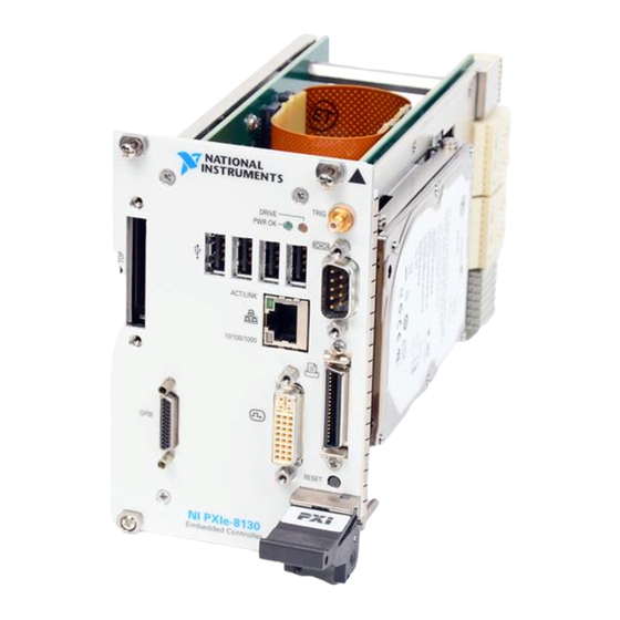
USB 2.0 ports, a PCI-based GPIB controller, Gigabit Ethernet, a reset button, and a PXI trigger. The NI PXIe-8130 has an AMD 2.3 GHz Turion 64 X2, 800 MHz HyperTransport Link, Dual Channel DDR2, 667 MHz memory controller, all the standard I/O, and a 40 GB (or larger) hard drive. -
Page 12: Functional Overview
NI PXIe-8130 embedded computer. NI PXIe-8130 Functional Description The NI PXIe-8130 is a modular PC in a PXI Express 3U-size form factor. Figure 1-1 is a functional block diagram of the NI PXIe-8130. Following the diagram is a description of each logic block shown. - Page 13 Chapter 1 Introduction The NI PXIe-8130 consists of the following logic blocks on the CPU module and the I/O (daughter card) module. The CPU module has the following logic blocks: • • • • • • • • • •...
-
Page 14: National Instruments Software
GPIB I/O Board National Instruments Software National Instruments has developed several software tools you can use with the NI PXIe-8130. National Instruments’ hardware and software work together to help you make the most of your PXI Express system. The LabVIEW, Measurement... - Page 15 RTSI or PXI synchronization, self-calibration, messaging, and acquiring data to extended memory. For more information visit National Instruments’ Modular Instruments use specialized drivers suited to each product’s specialization. Express VIs provide customized, interactive programming of instruments in a single interface and soft front panels provide an interface for testing the functionality of each instrument with no programming required.
-
Page 16: Cleaning
NI-VISA driver for Linux and NI Modular Instruments are partially supported. For more information visit Cleaning Use a dry, low-velocity stream of air to clean the NI PXIe-8130 controller. If needed, use a soft-bristle brush for cleaning around components. © National Instruments Corporation ni.com/visa... -
Page 17: Installation And Configuration
NI PXIe-8130 controller. Installing the NI PXIe-8130 This section contains general installation instructions for the NI PXIe-8130. Consult your PXI Express chassis user manual for specific instructions and warnings. Caution To protect both yourself and the chassis from electrical hazards, leave the chassis powered off until you finish installing the NI PXIe-8130 module. - Page 18 Figure 2-1. Removing Protective Screw Caps Make sure the injector/ejector handle is in its downward position. Align the NI PXIe-8130 with the card guides on the top and bottom of the system controller slot. Hold the handle as you slowly slide the module into the chassis until the handle catches on the injector/ejector rail.
- Page 19 13. Power on the chassis. 14. Verify that the controller boots. If the controller does not boot, refer Figure 2-2 shows an NI PXIe-8130 installed in the system controller slot of a National Instruments NI PXIe-1062Q chassis. 1 NI PXIe-1062Q Chassis 2 NI PXIe-8130 Controller ©...
-
Page 20: How To Remove The Controller From The Pxi Express Chassis
If the PXIe chassis Inhibit Mode Selector Switch is not in the Default position, any attempt to shut down the NI PXIe-8130 through the push button reset or using Windows will result in the controller Power OK LED blinking. The user will be required to use the Remote Inhibit pin on the Remote Inhibit and Voltage Monitoring Connector to turn off the chassis. -
Page 21: Main Setup Menu
System Memory—This value indicates the size of system RAM detected by the BIOS. System Time—This setting controls the time of day, which is stored in a battery-backed real-time clock. Most operating systems also Chapter 2 Installation and Configuration NI PXIe-8130 User Manual... -
Page 22: Advanced Setup Menu
• • • • NI PXIe-8130 User Manual include a way to change this setting. Use <+> and <–> in conjunction with <Enter> and <Tab> to change these values. System Date—This setting controls the date, which is stored in a battery-backed real-time clock. -
Page 23: Ide Configuration Submenu
Not Detected. If a hard disk drive is detected on the interface, the setting will indicate Hard Disk. Chapter 2 Installation and Configuration Primary IDE Master/Slave Submenus Serial-ATA 0 section for more information. Serial-ATA 0 section for more information. NI PXIe-8130 User Manual section... -
Page 24: Primary Ide Master/Slave Submenus
• • • • NI PXIe-8130 User Manual Type—This setting specifies type of device that the BIOS attempts to boot from. The default is Auto, which allows the BIOS to auto-detect the type of device connected to the IDE interface. -
Page 25: Serial-Ata 0 Primary/Secondary Channel Submenus
SMART capable, and if so, to enable the feature. 32Bit Data Transfer—This setting specifies whether or not 32-bit data transfers are enabled on supported hard disks. The default is Enabled. Chapter 2 Installation and Configuration NI PXIe-8130 User Manual... -
Page 26: Serial/Parallel Port Configuration Submenu
Certain real-time applications may require you to disable this setting to reduce loop time jitter. When the controller is configured to boot LabVIEW RT, legacy USB support is automatically disabled. NI PXIe-8130 User Manual Serial Port1 Address—This setting specifies base address and interrupt request level (IRQ) information for COM1. The setting can also be used to disable COM1. -
Page 27: Event Log Configuration Submenu
Mark all events as read—Use this option to mark all events in the system event log as read. Clear Event Log—Use this option to discard all events in the system event log. 2-11 Chapter 2 Installation and Configuration NI PXIe-8130 User Manual... -
Page 28: Video Configuration Submenu
Trigger Router Configuration Submenu Use this submenu to program the front panel trigger router configuration. • NI PXIe-8130 User Manual Onboard Video Adapter—This setting specifies whether or not the onboard video adapter is enabled. The default is Enabled. Primary Graphics Adapter—This setting specifies which video adapter the BIOS should use as the primary adapter if more than one is present. -
Page 29: Boot Setup Menu
If this setting is Disabled, the BIOS will not pause to allow the user to acknowledge an error during the boot process. The default is Enabled. 2-13 Chapter 2 Installation and Configuration NI PXIe-8130 User Manual... -
Page 30: Pxi Express Setup Menu
Use Switch Setting for each option. • Note Booting LabVIEW RT requires that your NI PXIe-8130 controller has an IDE (PATA) hard drive. Such a controller may be ordered from National Instruments with the part number 780032-33. • •... -
Page 31: Exiting The Bios Setup Utility
Save Changes and Exit—Any changes made to BIOS settings are stored in the battery-backed system CMOS. The setup program then exits and reboots the controller. The <F10> key can also be used to select this option. 2-15 Chapter 2 Installation and Configuration NI PXIe-8130 User Manual... -
Page 32: System Cmos
• • • System CMOS The NI PXIe-8130 contains memory backed up by a battery to store BIOS configuration information. Complete the following steps to clear the CMOS contents: Caution Do not leave the jumper on pins 2–3. Doing so decreases battery life and prevents the controller from booting. - Page 33 Chapter 2 Installation and Configuration 1 Clear CMOS Contents 2 Pin 1 3 Normal Operation (Default) Figure 2-3. Clearing the CMOS Contents © National Instruments Corporation 2-17 NI PXIe-8130 User Manual...
-
Page 34: Labview Rt Configuration Switches
The NI PXIe-8130 controller includes the following LabVIEW RT configuration switches: • Note Booting LabVIEW RT requires that your NI PXIe-8130 controller has an IDE (PATA) hard drive. Such a controller may be ordered from National Instruments with the part number 780032-33. • • •... -
Page 35: Drivers And Software
Figure 2-4. LabVIEW RT Configuration Switches images directory, you will find a images directory, and a directory. drivers 2-19 Chapter 2 Installation and Configuration in its root that images directory is logically organized into directory, manuals NI PXIe-8130 User Manual... -
Page 36: Pxi Express Features
PXI Express Features PXI Express Trigger Connectivity The SMB connector on the NI PXIe-8130 front panel can connect to or from any PXI backplane trigger line. A trigger allocation process is needed to prevent two resources from connecting to the same trigger line, resulting in the trigger being double-driven and possibly damaging the hardware. -
Page 37: Pxi System Configuration
Identify As submenu. Further expanding the PXI System branch shows all devices in the system that NI-VISA can recognize. 2-21 Chapter 2 Installation and Configuration file for identification. .ini NI PXIe-8130 User Manual... -
Page 38: Upgrading Ram
For detailed information about initialization files, refer to the PXI specification at Upgrading RAM You can change the amount of installed RAM on the NI PXIe-8130 by upgrading the SO-DIMMs. To upgrade the RAM, remove the NI PXIe-8130 from the PXI Express chassis. -
Page 39: Hard Drive Recovery
Your system hot key is <F4>. To access the hard drive-based recovery tool, press and Note hold <F4> when video first appears during the boot process. © National Instruments Corporation 2 DDR2 SO-DIMM Socket Figure 2-6. Installing a DDR2 SO-DIMM in an NI PXIe-8130 Controller ni.com/support 2-23 Chapter 2 Installation and Configuration... -
Page 40: Installing An Os
Recovering the OS erases the contents of your hard disk. Back up any files you want Note to keep. Installing an OS NI PXIe-8130 controllers include a preinstalled OS. In some cases, you may want to install a different OS. When doing so, consider the following guidelines. Installing from a USB CD/DVD-ROM The NI PXIe-8130 supports the installation of Windows Vista or Windows XP from a USB CD/DVD-ROM. -
Page 41: Expresscard
Slide the card out of the slot. Caution To avoid data loss and other potential issues, stop communication with your ExpressCard device before removing it from the NI PXIe-8130. In Windows, use the Safely Remove Hardware tool to safely stop the ExpressCard. © National Instruments Corporation Hold the card so the top side is facing left. -
Page 42: I/O Information
I/O Information Front Panel Connectors Table 3-1 lists various peripherals and their corresponding NI PXIe-8130 external connectors, bus interfaces, and functions. Table 3-1. NI PXIe-8130 Peripherals Overview Peripheral Video Serial Ethernet Parallel PXI trigger GPIB device ExpressCard/34 module © National Instruments Corporation... -
Page 43: Front Panel
NI PXIe-8130. Dimensions are in inches [millimeters]. NI PXIe-8130 User Manual 3.714 94.33 3.341 84.85 1.715 43.56 .000 0 [ ] Figure 3-1. NI PXIe-8130 Front Panel Layout and Dimensions 4.393 111.58 3.551 90.19 2.988 75.91 2.063 52.4 1.514 38.47 1.069... -
Page 44: Dvi-I
DVI-I Figure 3-2 shows the location and pinouts for the DVI connector on the NI PXIe-8130. Table 3-2 lists and describes the DVI connector signals. © National Instruments Corporation Figure 3-2. DVI Connector Location and Pinout Table 3-2. DVI-I Connector Signals TMDS Data2–... - Page 45 Chapter 3 I/O Information NI PXIe-8130 User Manual Table 3-2. DVI-I Connector Signals (Continued) TMDS Data1+ TMDS Data1/3 Shield Reserved Reserved +5 V Power Ground (for +5 V) Hot Plug Detect TMDS Data0– TMDSData0+ TMDS Data0/5 Shield Reserved Reserved TMDS Clock Shield TMDS Clock + TMDS Clock –...
-
Page 46: Com1
COM1 Figure 3-3 shows the location and pinouts for the COM1 connector on the NI PXIe-8130. Table 3-3 lists and describes the COM1 connector signal. AMP manufactures a serial port mating connector, part number 745491-5. Note: The pound symbol (#) indicates an active low signal. -
Page 47: Ethernet
I/O Information Ethernet Figure 3-4 shows the location and pinouts for the Ethernet connector on the NI PXIe-8130. Table 3-4 lists and describes the Ethernet connector signals. AMP manufactures a mating connector, part number 554739-1. NI PXIe-8130 User Manual Figure 3-4. Ethernet Connector Location and Pinout Table 3-4. - Page 48 LAN link is established. The controller is communicating with another computer on the LAN. 10 Mbit/sec data rate is selected. 100 Mbit/sec data rate is selected. 1000 Mbit/sec data rate is selected. Chapter 3 I/O Information Condition NI PXIe-8130 User Manual...
-
Page 49: Parallel Port
I/O Information Parallel Port Figure 3-5 shows the location and pinouts for the IEEE 1284 (parallel) connector on the NI PXIe-8130. Table 3-6 lists and describes the IEEE 1284 connector signals. Parallel port adapter cables are available from National Instruments, part number 777169-01. - Page 50 Chapter 3 I/O Information Signal Description Data Bit 2 Data Bit 3 Data Bit 4 Data Bit 5 Data Bit 6 Data Bit 7 Initialize Printer Strobe Select Input Auto Line Feed +5 V Ground Not Connected NI PXIe-8130 User Manual...
-
Page 51: Universal Serial Bus
Universal Serial Bus Figure 3-6 shows the location and pinouts for the Universal Serial Bus (USB) connector on the NI PXIe-8130. Each controller has 4 USB ports on the front panel. Table 3-7 lists and describes the USB connector signals. -
Page 52: Trigger
The TRIG connector is the software-controlled trigger connection for routing PXI triggers to or from the backplane trigger bus. Figure 3-7 shows the TRIG connector location on the NI PXIe-8130. Table 3-8 lists and describes the trigger connector signals. 2 (Shield) ©... -
Page 53: Gpib (Ieee 488.2)
Chapter 3 I/O Information GPIB (IEEE 488.2) Figure 3-8 shows the location and pinouts for the GPIB connector on the NI PXIe-8130. Table 3-9 lists and describes the GPIB connector signals. ITT Canon manufactures a GPIB mating connector, part number MDSM-25SC-Z11-V51. - Page 54 DIO8# REN# 18–25 3-13 Chapter 3 I/O Information Signal Description Not Data Accepted Interface Clear Service Request Attention Chassis ground Data Bit 5 Data Bit 6 Data Bit 7 Data Bit 8 Remote Enable Logic Ground NI PXIe-8130 User Manual...
-
Page 55: Expresscard/34 Slot
Chapter 3 I/O Information ExpressCard/34 Slot The NI PXIe-8130 controller is equipped with an ExpressCard/34 slot on the front panel, which provides I/O expansion and options for removable storage. Figure 3-9 shows the location and pinouts for the ExpressCard/34 slot on the NI PXIe-8130. - Page 56 PE Wake Power PE Reset Power Power Clock Request PE Presence Reference Clock – Reference Clock + Ground PE Data Receive – PE Data Receive + Ground PE Data Transmit – PE Data Transmit + Ground NI PXIe-8130 User Manual...
-
Page 57: Front Panel Features
The NI PXIe-8130 has the following front-panel features: • • Data Storage The NI PXIe-8130 has the following data storage features: • • NI PXIe-8130 User Manual A system reset pushbutton (press the button to generate a reset to the... -
Page 58: Common Configuration Questions
This chapter answers common configuration questions you may have when using a NI PXIe-8130 embedded controller. General Questions What do the LEDs on the NI PXIe-8130 front panel mean? Refer to the LED status descriptions in the Chapter 3, After shutting down my NI PXIe-8130 controller, the Ethernet LEDs continue to blink. -
Page 59: Boot Options
There are some limitations when booting from a USB device. Windows XP can be installed from a USB CD/DVD-ROM, but earlier versions of Windows cannot. The NI PXIe-8130 BIOS configures the USB devices so that they will work in a DOS environment. -
Page 60: Software Driver Installation
If you do not have a Y-splitter cable, plug a USB keyboard into any USB connector. You can also plug a USB mouse into any USB connector. How do I connect a standard 25-pin LPT cable to the NI PXIe-8130? The NI PXIe-8130 uses a type C LPT connector. Most parallel port devices use a type A connector. -
Page 61: Upgrade Information
How do I install software from a CD? The compact size of the NI PXIe-8130 does not allow for an integrated USB CD/DVD-ROM drive. If you are using Windows XP, you have the following options: •... - Page 62 National Instruments has tested and verified that the DDR2 SO-DIMMs we sell Note work with the NI PXIe-8130. We recommend you purchase your DDR2 SO-DIMM modules from National Instruments. Other off-the-shelf DDR2 SO-DIMM modules are not guaranteed to work properly.
-
Page 63: Pxi Express Configuration
3H3COSD8, What Peripheral Drivers Should I Use with My PXI or VXI Controller?, at My NI PXIe-8130 does not have an internal floppy drive. Is there a way to use an external drive? Yes. The NI PXIe-8130 controller supports and can boot from USB floppy drives. -
Page 64: Troubleshooting
This chapter answers common troubleshooting questions you may have when using the NI PXIe-8130 embedded computer. What if the NI PXIe-8130 does not boot? Several problems can cause a controller not to boot. Here are some things to look for and possible solutions. - Page 65 My CMOS is corrupted. How do I set it back to default? As an alternative method, complete the following steps: NI PXIe-8130 User Manual Recover the hard drive on the controller. (Refer to the Recovery section of Chapter 2, Make sure the RAM is properly seated.
- Page 66 Move the jumper on W2 from pins 1–2 to pins 2–3 as shown in Figure 5-1. Wait one second. Move the jumper back to pins 1–2. Reinstall the controller in the chassis. 2 Pin 1 Figure 5-1. Clearing the CMOS Contents Chapter 5 Troubleshooting 3 Normal Operation (Default) NI PXIe-8130 User Manual...
-
Page 67: Specifications
Specifications This appendix lists the electrical, mechanical, and environmental specifications of the NI PXIe-8130 embedded controller. Features On-die L2 cache Dual-Channel DDR2 RAM, PC2 5300 Hard Drive Ethernet PXI Express 4 Link Configuration PXI Express 2 Link Configuration GPIB (IEEE 488 Controller) - Page 68 Maximum altitude...2,000 m (800 mbar) Pollution Degree ...2 Indoor use only. Caution Clean the NI PXIe-8130 with a soft nonmetallic brush. Make sure that the device is completely dry and free from contaminants before returning it to service. NI PXIe-8130 User Manual Voltage (V) Typical +3.3 V...
-
Page 69: Operating Environment
MIL-PRF-28800F Class 2 high temperature limit.) (Tested in accordance with IEC-60068-2-56.) accordance with IEC-60068-2-1 and IEC-60068-2-2. Meets MIL-PRF-28800F Class 3 low temperature limit.) accordance with IEC-60068-2-1 and IEC-60068-2-2. Meets MIL-PRF-28800F Class 3 limits.) (Tested in accordance with IEC-60068-2-56.) NI PXIe-8130 User Manual... -
Page 70: Electromagnetic Compatibility
• • • For EMC compliance, operate this device according to product documentation. Note NI PXIe-8130 User Manual Operating ...5 to 500 Hz, 0.3 g Nonoperating ...5 to 500 Hz, 2.4 g IEC 61010-1, EN-61010-1 UL 61010-1, CSA 61010-1 , search by model number or product line, and click the EN 61326 EMC requirements;... -
Page 71: Environmental Management
Waste Electrical and Electronic Equipment (WEEE) At the end of their life cycle, all products must be sent to a WEEE recycling EU Customers center. For more information about WEEE recycling centers and National Instruments WEEE initiatives, visit National Instruments... -
Page 72: Technical Support And Professional Services
Technical Support and Professional Services Visit the following sections of the National Instruments Web site at ni.com • • • • © National Instruments Corporation for technical support and professional services: Support—Online technical support resources at include the following: –... - Page 73 You also can visit the Worldwide Offices section of office Web sites, which provide up-to-date contact information, support phone numbers, email addresses, and current events. NI PXIe-8130 User Manual and could not find the answers you need, contact ni.com ni.com/niglobal to access the branch ni.com...
- Page 74 Basic Input/Output System—BIOS functions are the fundamental level of any PC or compatible computer. BIOS functions embody the basic operations needed for successful use of the computer’s hardware resources. © National Instruments Corporation Value –9 – 6 –3 tera NI PXIe-8130 User Manual...
- Page 75 LCD computer displays and digital projectors. It was developed by an industry consortium, the Digital Display Working Group (DDWG). Extended Capabilities Parallel. EEPROM Electronically Erasable Programmable Read Only Memory. Electromagnetic Compatibility. Electromagnetic interference. NI PXIe-8130 User Manual ni.com...
- Page 76 LabWindows/CVI or LabVIEW. interrupt A means for a device to request service from another device. interrupt level The relative priority at which a device can interrupt. © National Instruments Corporation Glossary NI PXIe-8130 User Manual...
- Page 77 Mean time between failure. NI-488 or NI-488.2 The National Instruments software for GPIB systems. NI-DAQ The National Instruments software for data acquisition instruments. NI-VISA The National Instruments implementation of the VISA standard—An interface-independent software that provides a unified programming interface for VXI, GPIB, and serial instruments.
- Page 78 SO-DIMM Small Outline Dual In-line Memory Module. SPI Bus Serial Peripheral Interface—A standard for controlling most any digital electronics that accept a clocked serial stream of bits. © National Instruments Corporation Glossary NI PXIe-8130 User Manual...
- Page 79 Glossary Universal Serial Bus. Volts. Video Graphics Array—The minimum video display standard for all PCs. Watts. NI PXIe-8130 User Manual ni.com...
- Page 80 3-16 DDR SO-DIMMs installing, 2-22, 4-4 figure, 2-23, 4-5 DDR2 SO-DIMMs from National Instruments (note), 2-22, Declaration of Conformity (NI resources), B-1 diagnostic tools (NI resources), B-1 directories and files installed on hard drive, 2-19 NI PXIe-8130 User Manual...
- Page 81 3-11 USB, 3-1, 3-10 video, 3-3 dimensions, 3-2 features, 3-16 LEDs, 4-1 functional overview of NI PXIe-8130, 1-3 GPIB (IEEE 488.2), 3-12 connector location and pinout (figure), 3-12 connector signals (table), 3-12 driver installation, 4-4 GPIB device connector, 3-1...
- Page 82 NI PXIe-8130 installed in a PXI Express chassis (figure), 2-3 procedure, 2-1 removing NI PXIe-8130 from PXI Express chassis, 2-4 removing protective screw caps (figure), 2-2 installing an OS from USB CD/DVD-ROM, 2-24 overview, 2-24 installing the GPIB driver, 4-4...
- Page 83 4-1 Serial ATA Hard Disk, 1-4 serial port, 3-1 serial/parallel port configuration BIOS menu, 2-10 setting up the NI PXIe-8130 BIOS, 2-4 shock and vibration specifications, A-4 socket S1 CPU, 1-4 SO-DIMM logic block, 1-4 software See also drivers...
- Page 84 3-1 See also VGA driver installation, 4-3 Waste Electrical and Electronic Equipment (WEEE) specifications, A-5 Web resources, B-1 Y-splitter cable figure, 4-3 using mouse and keyboard without, 4-3 using with PS/2 mouse and keyboard, 2-3 Index NI PXIe-8130 User Manual...
Need help?
Do you have a question about the NI PXIe-8130 and is the answer not in the manual?
Questions and answers