National Instruments NI PXI-7831R User Manual
Reconfigurable i/o
Hide thumbs
Also See for NI PXI-7831R:
- Where to start (11 pages) ,
- User manual (75 pages) ,
- Getting started (17 pages)

Related Manuals for National Instruments NI PXI-7831R


Summary of Contents for National Instruments NI PXI-7831R
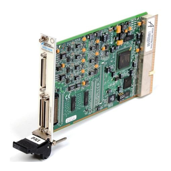
- Page 1 Reconfigurable I/O NI PXI-7831R User Manual Reconfigurable I/O Devices for PXI/CompactPCI Bus Computers NI PXI-7831R User Manual April 2003 Edition Part Number 370489A-01...
- Page 2 Switzerland 41 56 200 51 51, Taiwan 886 2 2528 7227, United Kingdom 44 0 1635 523545 For further support information, see the Technical Support and Professional Services appendix. To comment on the documentation, send email to techpubs@ni.com. © 2003 National Instruments Corporation. All rights reserved.
-
Page 3: Important Information
Warranty The NI PXI-7831R is warranted against defects in materials and workmanship for a period of one year from the date of shipment, as evidenced by receipts or other documentation. National Instruments will, at its option, repair or replace equipment that proves to be defective during the warranty period. - Page 4 These classes are known as Class A (for use in industrial-commercial locations only) or Class B (for use in residential or commercial locations). All National Instruments (NI) products are FCC Class A products. Depending on where it is operated, this Class A product could be subject to restrictions in the FCC rules. (In Canada, the Department of Communications (DOC), of Industry Canada, regulates wireless interference in much the same way.) Digital...
-
Page 5: Table Of Contents
RT Module...1-9 Cables and Optional Equipment ...1-9 Custom Cabling ...1-10 Unpacking ...1-11 Safety Information ...1-11 Chapter 2 Hardware Overview of the NI PXI-7831R Analog Input ...2-2 Input Modes...2-3 Input Range ...2-3 Connecting Analog Input Signals ...2-4 Types of Signal Sources ...2-5 Floating Signal Sources...2-6... - Page 6 Loading Calibration Constants ... 3-1 Internal Calibration... 3-1 External Calibration... 3-2 Appendix A Specifications Appendix B Connecting I/O Signals Appendix C Using the SCB-68 Shielded Connector Block Appendix D Technical Support and Professional Services Glossary NI PXI-7831R User Manual ni.com...
-
Page 7: About This Manual
National Instruments PXI-7831R device and contains information concerning its operation and programming. The NI PXI-7831R device is a Reconfigurable I/O (RIO) device. The NI PXI-7831R contains eight independent, 16-bit analog input (AI) channels, eight independent, 16-bit analog output (AO) channels, and 96 digital I/O (DIO) lines. -
Page 8: Reconfigurable I/O Documentation
Reconfigurable I/O Documentation The NI PXI-7831R User Manual is one piece of the documentation set for your RIO system and application. Depending on the hardware and software you use for your application, you could have any of several types of documentation. -
Page 9: Introduction
8 independent, 16-bit analog input (AI) channels. A user-reconfigurable field-programmable gate array (FPGA) controls the digital and analog I/O on the NI PXI-7831R. The FPGA on the RIO device allows you to define the functionality and timing of the device, whereas traditional multifunction I/O (MIO) devices have a fixed functionality provided by an application-specific integrated circuit (ASIC). -
Page 10: Using Pxi With Compactpci
PICMG CompactPCI 2.0 R3.0. PXI-specific features are implemented on the J2 connector of the CompactPCI bus. Table 1-1 lists the J2 pins used by the NI PXI-7831R. The NI PXI-7831R is compatible with any CompactPCI chassis with a sub-bus that does not drive these lines. -
Page 11: What You Need To Get Started
This section contains two lists that detail what you need to get started using the NI PXI-7831R with Windows 2000/XP or the RT Module. Getting Started with Windows 2000/XP To set up and use the NI PXI-7831R with Windows 2000/XP, you need the following items: ❑... -
Page 12: Getting Started With The Rt Module
Chapter 1 Introduction ❑ ❑ Getting Started with the RT Module To set up and use the NI PXI-7831R with the FPGA Module and the RT Module, you need the following items: ❑ ❑ ❑ ❑ ❑ ❑ NI PXI-7831R User Manual... -
Page 13: Overview Of Reconfigurable I/O
This section introduces the concept of RIO and describes how to use the reconfigurable FPGA to build high-level functions in hardware. Refer to Chapter 2, descriptions of the physical I/O resources available on the NI PXI-7831R. Reconfigurable I/O Concept The NI PXI-7831R device is based on a reconfigurable FPGA core surrounded by fixed I/O resources. -
Page 14: User-Defined I/O Resources
The fixed I/O resources include A/D converters (ADCs), D/A converters (DACs), digital input or output lines, or other I/O resources. Software accesses the RIO device through the bus interface, and the FPGA provides NI PXI-7831R User Manual FPGA Bus Interface Figure 1-1. - Page 15 The application in Figure 1-3 uses relatively few I/O resources and has enough logic left over for several large functions. DIO<0..7> Bus Interface DIO<8..15> Figure 1-2. FPGA Logic Use in an Application with Many Fixed I/O Resources © National Instruments Corporation NI PXI-7831R User Manual...
-
Page 16: Reconfigurable I/O Applications
Software Development You can use LabVIEW with the FPGA Module to program the NI PXI-7831R. To develop real-time applications that control the NI PXI-7831R, you can use the RT Module with LabVIEW and the FPGA Module. NI PXI-7831R User Manual Bus Interface Figure 1-3. -
Page 17: Fpga Module
A software utility installed with the NI-RIO Device Drivers CD allows users without the FPGA module to configure the NI PXI-7831R analog input mode, synchronize to the PXI clock, and configure the device to automatically load FPGA VIs when powered on. -
Page 18: Custom Cabling
Custom Cabling NI offers a variety of cables that you can use to connect signals to the NI PXI-7831R. If you need to develop a custom cable, NI provides a generic un-terminated shielded cable that makes this task easier. The NI PXI-7831R User Manual Table 1-2. -
Page 19: Unpacking
This cable ships with a wire list identifying which wire corresponds to which NI PXI-7831R pin. Using this cable, you can quickly connect the NI PXI-7831R signals that you need to the connector of your choice without having to connect these signals to the VHDCI connector end of the cable. - Page 20 NI PXI-7831R in such an environment, it must be in a suitably rated enclosure. If you need to clean the NI PXI-7831R, use a soft, nonmetallic brush. Make sure that the NI PXI-7831R is completely dry and free from contaminants before returning it to service.
- Page 21 Installation Category IV is for measurements performed at the primary electrical supply installation (<1,000V). Examples include electricity meters and measurements on primary overcurrent protection devices and on ripple control units. 1-13 Chapter 1 Introduction NI PXI-7831R User Manual...
-
Page 22: Hardware Overview Of The Ni Pxi-7831R
This chapter presents an overview of the hardware functions and I/O connectors on the NI PXI-7831R. Figure 2-1 shows a block diagram for the NI PXI-7831R, and Figure 2-2 shows the parts locator diagrams for the NI PXI-7831R. Input Mux AI–... -
Page 23: Analog Input
Hardware Overview of the NI PXI-7831R Analog Input The NI PXI-7831R has eight independent, 16-bit AI channels that can be simultaneously sampled or sampled at different rates. The input mode is software configurable, and the input range is fixed at ±10 V. The converters return data in two’s complement format. -
Page 24: Input Modes
Input Mode DIFF When the NI PXI-7831R is configured in DIFF input mode, each channel uses two AI lines. The positive input pin connects to the positive terminal of the onboard instrumentation amplifier, and the negative input pin connects to the negative input of the instrumentation amplifier. -
Page 25: Connecting Analog Input Signals
Summary. AIGND is a common AI signal that is routed directly to the ground tie point on the NI PXI-7831R. You can use this signal for a general analog ground tie point to the NI PXI-7831R, if necessary. Connection of AI signals to the NI PXI-7831R depends on the input mode of the AI channels you are using and the type of input signal source. -
Page 26: Types Of Signal Sources
The instrumentation amplifier applies common-mode voltage rejection and presents high input impedance to the AI signals connected to the NI PXI-7831R. Signals are routed to the positive and negative inputs of the instrumentation amplifier through input multiplexers on the device. -
Page 27: Floating Signal Sources
An instrument or device that has an isolated output is a floating signal source. You must tie the ground reference of a floating signal to the NI PXI-7831R AIGND through a bias resistor to establish a local or onboard reference for the signal. Otherwise, the measured input signal varies as the source floats out of the common-mode input range. - Page 28 – AI< i > – AISENSE – AIGND< i > Figure 2-4. Summary of Analog Input Connections Hardware Overview of the NI PXI-7831R Grounded Signal Source Examples • Plug-in Instruments with Nonisolated Outputs AI< i >(+) – AI< i >(–) –...
-
Page 29: Differential Connection Considerations (Diff Input Mode)
NI PXI-7831R configured in DIFF input mode. NI PXI-7831R User Manual The input signal is low-level (less than 1 V). The leads connecting the signal to the NI PXI-7831R are greater than 3 m (10 ft). The input signal requires a separate ground-reference point or return signal. -
Page 30: Differential Connections For Nonreferenced Or Floating Signal Sources
With this connection type, the instrumentation amplifier rejects both the common-mode noise in the signal and the ground potential difference between the signal source and the NI PXI-7831R ground, shown as V in Figure 2-5. In addition, the instrumentation amplifier can reject common-mode noise pickup in the leads connecting the signal sources to the device. - Page 31 Chapter 2 Hardware Overview of the NI PXI-7831R Bias Resistors Floating (see text) Signal Source – Bias Current Return Paths I/O Connector Figure 2-6 shows two bias resistors connected in parallel with the signal leads of a floating signal source. If you do not use the resistors and the...
-
Page 32: Single-Ended Connection Considerations
Single-Ended Connection Considerations A single-ended connection is one in which the NI PXI-7831R AI signal is referenced to a ground that can be shared with other input signals. The input signal is tied to the positive input of the instrumentation amplifier, and the ground is tied to the negative input of the instrumentation amplifier. -
Page 33: Single-Ended Connections For Floating Signal Sources (Rse Input Mode)
Sources (NRSE Input Mode) To measure a grounded signal source with a single-ended input mode, you must configure the NI PXI-7831R in the NRSE input mode. The signal is then connected to the positive input of the NI PXI-7831R instrumentation NI PXI-7831R User Manual AI–... -
Page 34: Common-Mode Signal Rejection Considerations
If the input circuitry of a NI PXI-7831R were referenced to ground, in this situation as in RSE input mode, this difference in ground potentials would appear as an error in the measured voltage. -
Page 35: Analog Output
Analog Output The NI PXI-7831R has eight 16-bit AO channels. The bipolar output range is fixed at ±10 V. Some applications require that the AO channels power-on to known voltage levels. To set the power-on levels, you can configure the NI PXI-7831R to automatically load and run your VI when the system powers on. -
Page 36: Digital I/O
DGND and DIO<0..39>. DIO<0..n> are the signals making up the DIO port, and DGND is the ground reference signal for the DIO port. The NI PXI-7831R has one MIO and two DIO connectors for a total of 96 DIO lines. - Page 37 NI is not liable for any damage resulting from such signal connections. Do not short the DIO lines of the NI PXI-7831R directly to power or to ground. Doing so can damage the NI PXI-7831R by causing excessive current to flow through the DIO lines.
- Page 38 LED shown in the figure. The NI PXI-7831R SH68-C68-S shielded cable contains 34 twisted pairs of conductors. To maximize the digital I/O available on the NI PXI-7831R, some of the DIO lines are twisted with power or ground as they are run through the cable, and some DIO lines are twisted with other DIO lines as they are run through the cable.
-
Page 39: Pxi Trigger Bus
These trigger lines connect to the FPGA on the NI PXI-7831R and can be used just like any of the other NI PXI-7831R DIO lines. The PXI trigger lines can be used to synchronize an NI PXI-7831R to any other device that supports PXI triggers. -
Page 40: Pxi Local Bus
Do not enable the local bus lines on an adjacent device if the device drives anything other than 0–3.3V LVTTL signal levels on the NI PXI-7831R. Enabling the lines in this way can damage the NI PXI-7831R. NI is not liable for any damage resulting from enabling such lines. -
Page 41: Switch Settings
PXI/LBLSTAR<0..12>. Each device receives its trigger signal on its own dedicated star trigger line. Do not configure the NI PXI-7831R and another device to drive the same physical Caution star trigger line simultaneously. Such signal driving can damage the NI PXI-7831R and the other device. -
Page 42: Power Connections
3. Note When the NI PXI-7831R is powered on with switch 1 in the ON position, the analog circuitry does not return properly calibrated data. For this reason, the switch should only be switched to the ON position while you are using software to reconfigure the NI PXI-7831R for the desired power-up behavior. - Page 43 Separate NI PXI-7831R signal lines from high-current or high-voltage lines. These lines can induce currents in or voltages on the NI PXI-7831R signal lines if they run in parallel paths at a close distance. To reduce the magnetic coupling between lines, separate them by a reasonable distance if they run in parallel, or run the lines at right angles to each other.
-
Page 44: Calibration
AO channels in the FPGA VI is already calibrated. Three levels of calibration are available for the NI PXI-7831R to ensure the accuracy of its analog circuitry. The first level, loading calibration constants, is the fastest, easiest, and least accurate. The intermediate level, internal calibration, is the preferred method of assuring accuracy in your application. -
Page 45: External Calibration
The results of an internal calibration can be stored in the flash memory on the NI PXI-7831R so that the CalDACs are automatically loaded with the newly calculated calibration constants the next time the NI PXI-7831R is powered on. -
Page 46: Specifications
Specifications This appendix lists the specifications of the NI PXI-7831R. These specifications are typical at 25 °C unless otherwise noted. Analog Input Input Characteristics Number of channels ... 8 Input modes... DIFF, RSE, NRSE Type of ADC... Successive approximation Resolution ... 16 bits, 1 in 65,536 Conversion time ... -
Page 47: Appendix A Specifications
DNL ...–1.0 to +2.0 LSB max No missing codes resolution...16 bits typ, 15 bits min CMRR, DC to 60 Hz ...86 dB Dynamic Characteristics Bandwidth System noise ...1.8 LSB NI PXI-7831R User Manual Absolute Accuracy Noise + Quantization (µV) Offset... -
Page 48: Output Characteristics
24 Hours 1 Year Offset ( 0.0335 0.0351 Appendix A Specifications Accuracy 4 LSB 2 LSB µ µ 10.3 µ µ µ µ Absolute Accuracy at Temp Drift Full Scale µ (%/ °C) (mV) 2366 0.0005 5.88 NI PXI-7831R User Manual... -
Page 49: Voltage Output
Protection ...Short-circuit to ground Power-on state ...User configurable Dynamic Characteristics Settling time Slew rate ...10 V/ Noise ...150 Glitch energy at midscale transition ...±100 mV for 3 NI PXI-7831R User Manual Step Size 16 LSB µ ±20.0 V µ ±2.0 V µ... - Page 50 Protection Reconfigurable FPGA Number of logic slices ... 5, 120 Available embedded RAM... 16, 384 KB Timebase ... 40 MHz © National Instruments Corporation NI PXI-7831R... 96 input/output Level = –I (sink) (source) Input ... –0.5 to 7.0 V Output ... Short-circuit (up to eight lines Equivalent number of logic cells ...
-
Page 51: Power Requirement
Timebase accuracy Calibration Recommended warm-up time...15 minutes Calibration interval ...1 year Onboard calibration reference Note To generate a calibration certificate for the NI PXI-7831R, click On-line Calibration Certificates at Bus Interface PXI...Master, slave Power Requirement +5 VDC (±5%) +3.3 VDC (±5%) Power available at I/O connectors ...+4.65 to +5.25 VDC at 1 A total,... - Page 52 Humidity ... 10 to 90% RH, noncondensing Maximum altitude ... 2,000 meters Pollution Degree (indoor use only) ... 2 Safety The NI PXI-7831R devices meet the requirements of the following standards for safety and electrical equipment for measurement, control, and laboratory use: •...
-
Page 53: Electromagnetic Compatibility
Refer to the Declaration of Conformity (DoC) for this product for any additional Note regulatory compliance information. To obtain the DoC for this product, click Declaration of Conformity Information at NI PXI-7831R User Manual FCC Part 15A above 1 GHz Table 1 (Class A) Compliant ni.com/hardref.nsf/... -
Page 54: Appendix B Connecting I/O Signals
This appendix describes how to make input and output signal connections to the NI PXI-7831R I/O connectors. The NI PXI-7831R has two DIO connectors with 40 DIO lines per connector, and one MIO connector with eight AI lines, eight AO lines, and 16 DIO lines. - Page 55 Connecting I/O Signals Figure B-2 shows the I/O connector pin assignments for the I/O connectors on the NI PXI-7831R. The DIO connector pin assignment applies to connectors<1..2> on the NI PXI-7831R. The MIO connector pin assignment applies to connector 0 on the NI PXI-7831R.
- Page 56 DIO6 DGND DIO5 DGND DIO4 DGND DIO3 DGND DIO2 DGND DIO1 DGND DIO0 Figure B-2. NI PXI-7831R I/O Connector Pin Assignments Appendix B Connecting I/O Signals 34 68 AI0- AI0+ AIGND1 33 67 AIGND0 32 66 AI1- AI1+ 31 65...
- Page 57 Connections that exceed any of the maximum ratings of input or output signals on the NI PXI-7831R can damage the NI PXI-7831R and the computer. Maximum input ratings for each signal are given in the Protection column of Table B-2. NI is not liable for...
- Page 58 AO = Analog Output Connecting to 5B and SSR Signal Conditioning NI provides cables that allow you to connect signals from the NI PXI-7831R directly to 5B backplanes for analog signal conditioning and SSR backplanes for digital signal conditioning. © National Instruments Corporation Table B-2.
- Page 59 NI PXI-7831R MIO connector directly to 5B and SSR backplanes. This cable has a 68-pin male VHDCI connector on one end that plugs into the NI PXI-7831R MIO connector. The other end of this cable provides two 26-pin female headers plus one 50-pin female header.
- Page 60 NI PXI-7831R DIO connectors directly to SSR backplanes for digital signal conditioning. This cable has a 68-pin male VHDCI connector on one end that plugs into the NI PXI-7831R DIO connectors. The other end of this cable provides two 50-pin female headers.
- Page 61 NSC68-5050 cable header. In this case, you only have access to the channels that exist on both the SSR backplane and the NSC68-5050 cable header you are using. Figure B-4 shows the connector pinouts when using the NSC68-5050 cable. NI PXI-7831R User Manual DIO23 DIO22 DIO21 DIO20...
- Page 62 NI PXI-7831R with the SCB-68 shielded connector block. The SCB-68 has 68 screw terminals for I/O signal connections. To use the SCB-68 with the NI PXI-7831R, you must configure the SCB-68 as a general-purpose connector block. Refer to Figure C-1 for the general-purpose switch configuration.
-
Page 63: Quick Reference Label
AI6+ DIO24 AOGND0 AI6- DGND AIGND6 DIO23 AOGND0 AIGND7 DGND AI7+ DIO22 AI7- DGND AISENSE Figure C-2. SCB-68 Quick Reference Label for the NI PXI-7831R PIN# DGND DGND DIO11 DIO0 DGND DGND DGND DIO12 DIO0 DIO1 DGND DGND DGND DIO13... -
Page 64: Technical Support And Professional Services
Technical Support and Professional Services Visit the following sections of the National Instruments Web site at ni.com • • • • © National Instruments Corporation for technical support and professional services: Support—Online technical support resources include the following: – Self-Help Resources—For immediate answers and solutions,... - Page 65 Worldwide Offices section of office Web sites, which provide up-to-date contact information, support phone numbers, email addresses, and current events. NI PXI-7831R User Manual Calibration Certificate—If your product supports calibration, you can obtain the calibration certificate for your product at ni.com/calibration...
- Page 66 < Less than. ≤ Less than or equal to. – Negative of, or minus. Ω Ohms. Per. Percent. ± Plus or minus. Positive of, or plus. © National Instruments Corporation Value –12 –9 – 6 –3 NI PXI-7831R User Manual...
- Page 67 Application-Specific Integrated Circuit—a proprietary semiconductor component designed and manufactured to perform a set of specific functions. bipolar A signal range that includes both positive and negative values (for example, –5 to +5 V). NI PXI-7831R User Manual © National Instruments Corporation...
- Page 68 Decibel—the unit for expressing a logarithmic measure of the ratio of two signal levels: dB = 20log10 V1/V2, for signals in volts. Direct current. DGND Digital ground signal. DIFF Differential mode. © National Instruments Corporation Glossary NI PXI-7831R User Manual...
- Page 69 FPGA VI A configuration that is downloaded to the FPGA and that determines the functionality of the hardware. glitch An unwanted signal excursion of short duration that is usually unavoidable. Hour. Hardware-in-the-loop. Hertz. NI PXI-7831R User Manual © National Instruments Corporation...
- Page 70 Multiplexer—a switching device with multiple inputs that sequentially connects each of its inputs to its output, typically at high speeds, in order to measure several signals with a single analog input channel. © National Instruments Corporation Glossary NI PXI-7831R User Manual...
- Page 71 (2) A digital port, consisting of four or eight lines of digital input and/or output. Parts per million. Pull-up. Pulse-width modulation. Stands for PCI eXtensions for Instrumentation. PXI is an open specification that builds off the CompactPCI specification by adding instrumentation-specific features. NI PXI-7831R User Manual © National Instruments Corporation...
- Page 72 The voltage rate of change as a function of time. The maximum slew rate of an amplifier is often a key specification to its performance. Slew rate limitations are first seen as distortion at higher signal frequencies. © National Instruments Corporation Glossary NI PXI-7831R User Manual...
- Page 73 Virtual instrument—program in LabVIEW that models the appearance and function of a physical instrument. Volts, input high. Volts, input low. Volts, output high. Volts, output low. Volts, root mean square. waveform Multiple voltage readings taken at a specific sampling rate. NI PXI-7831R User Manual © National Instruments Corporation...
Need help?
Do you have a question about the NI PXI-7831R and is the answer not in the manual?
Questions and answers