
Related Manuals for National Instruments NI 9478


Summary of Contents for National Instruments NI 9478
- Page 1 OPERATING INSTRUCTIONS AND SPECIFICATIONS NI 9478 16-Channel, 0–50 V, Sinking Digital Output Module with Programmable Current Limits Français Deutsch ni.com/manuals...
- Page 2 This document describes how to use the National Instruments 9478 and includes specifications and pin assignments for the NI 9478. Visit ni.com/info which software you need for the modules you are using. For information about installing, configuring, and programming the system, refer to the system documentation.
-
Page 3: Safety Guidelines For Hazardous Locations
Touching this component may result in bodily injury. Safety Guidelines for Hazardous Locations The NI 9478 is suitable for use in Class I, Division 2, Groups A, B, C, D, T4 hazardous locations; Class I, Zone 2, AEx nA IIC T4, and Ex nA IIC T4 hazardous locations;... - Page 4 II 3G and is suitable for use in Zone 2 hazardous locations. If you are using the NI 9478 in Gas Group IIC hazardous locations or in ambient temperatures of –40 °C ≤ Ta ≤ 70 °C, you must use the device in an NI chassis that has been evaluated as EEx nC IIC T4, Ex nA IIC T4, or Ex nL IIC T4 equipment.
- Page 5 Power supply and module cables must be separated on opposite sides of the enclosure and must enter and exit through opposing enclosure walls. © National Instruments Corp. and search for the LR certificate, NI 9478 Operating Instructions and Specifications...
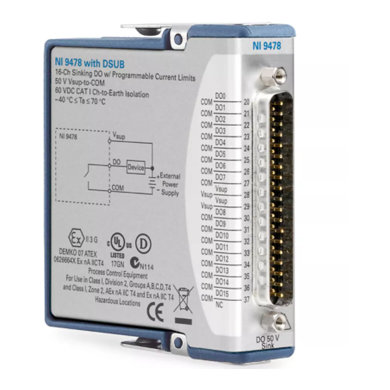
- Page 6 Connecting the NI 9478 The NI 9478 has a 37-pin DSUB connector that provides connections for the 16 digital output channels. Figure 1. NI 9478 Pin Assignments NI 9478 Operating Instructions and Specifications Vsup Vsup Vsup Vsup DO10 DO11 DO12...
- Page 7 Each channel of the NI 9478 has a DO pin to which you can connect the load you want to control. Each channel also has a COM pin. National Instruments recommends you provide independent COM wiring for each channel to minimize current flow in the COM wiring.
- Page 8 NI 9478. Cable Clamp NI 9478 Figure 2. Connecting a Device to the NI 9478 You must connect the V weak cable clamping diode that protects the module from cable inductance flyback. This flyback voltage results from small amounts of energy stored in the inductance of the cabling.
- Page 9 Figure 3. Refer to the information about protection from cable inductance flyback. Cable Clamp NI 9478 Figure 3. Connecting a Flyback Diode to the NI 9478 © National Instruments Corp. Using Long Cables Device NI 9478 Operating Instructions and Specifications...
- Page 10 Each time a channel is turned off, the energy stored in the cables is released as flyback voltage and dissipates as heat in the NI 9478. The total power dissipated in the module increases with higher switching frequencies, higher currents, and longer cable lengths.
- Page 11 COM pin, as shown in Figure 5. Cable Clamp NI 9478 Figure 5. Cable Length of the NI 9478 with a Capacitor and Diode © National Instruments Corp. μ F. In this case, the effective length of the Load...
-
Page 12: Overcurrent Protection
Output Current Limit Thresholds The NI 9478 provides two configurable current limit thresholds for the module, Limit A and Limit B. The NI 9478 continuously monitors the current through each output channel and detects if the current exceeds either of the current limit thresholds. You can... - Page 13 Visit ni.com/info about C Series documentation. The NI 9478 is not protected against output Caution overcurrent or short-circuit conditions when overcurrent protection is disabled. If you disable overcurrent protection, ensure that the wiring is correct and that you are operating the NI 9478 within the specifications.
- Page 14 2 meters of cabling. For other operating conditions, you can find the safe operating specifications for the NI 9478 by calculating the percentage of the total allowable power each output channel...
- Page 15 To verify that your application keeps the NI 9478 within safe operating specifications, calculate the average percentage of total allowable power each channel uses, then add together the percentages for all the channels.
- Page 16 Example One You are driving a load with 2.0 meters of cable through a cycle in μ which the NI 9478 is on and passing 1.25 A of current for 40 μ μ μ μ then off for 10 s. The output period is 50...
- Page 17 You are driving a load with 2.0 meters of cable through a cycle in which the NI 9478 first is constantly on and passing 3 A of current for 0.25 seconds, then drives the load at 20 kHz with 1.25 A current for 1.25 seconds, then drives the load off for 4 seconds.
-
Page 18: Sleep Mode
In sleep mode, the system consumes minimal power and may dissipate less heat than it does in normal mode. Refer to the Specifications section for more information about power consumption and thermal dissipation. NI 9478 Operating Instructions and Specifications ni.com... -
Page 19: Specifications
Four channels on ... 2.5 A max One channel on... 5 A max Refer to the Safe Operating Current operating current. © National Instruments Corp. , per channel section for more information about safe NI 9478 Operating Instructions and Specifications... - Page 20 Current limit accuracy ... 130 mA + 3% of setting, max Using up to 2 meters of cabling on each output channel. Refer to the Current section for more information. NI 9478 Operating Instructions and Specifications , per channel , per channel ) ... 50 mΩ max Safe Operating ni.com...
- Page 21 Contact NI for Bellcore MTBF specifications Note at other temperatures or for MIL-HDBK-217F specifications. © National Instruments Corp. No Limit μ μ s in 10 increments Bellcore Issue 6, Method 1, Case 3, Limited Part Stress Method NI 9478 Operating Instructions and Specifications μ...
-
Page 22: Power Requirements
Active mode ... 1.5 W max Sleep mode ... 25 Physical Characteristics If you need to clean the module, wipe it with a dry towel. Weight... 148 g (5.2 oz) NI 9478 Operating Instructions and Specifications μ W max μ W max... - Page 23 Such voltage measurements include signal levels, special equipment, limited-energy parts of equipment, circuits powered by regulated low-voltage sources, and electronics. Do not connect the NI 9478 to signals or use for Caution measurements within Measurement Categories II, III, or IV.
-
Page 24: Isolation Voltages
For UL and other safety certifications, refer to the Note product label or visit by module number or product line, and click the appropriate link in the Certification column. NI 9478 Operating Instructions and Specifications channels Measurement Category I dielectric withstand test ni.com/certification , search ni.com... - Page 25 Europe (DEMKO)... Ex nA IIC T4 Environmental National Instruments C Series modules are intended for indoor use only but may be used outdoors if installed in a suitable enclosure. Refer to the manual for the chassis you are using for more information about meeting these specifications.
-
Page 26: Shock And Vibration
Random (IEC 60068-2-64)... 5 g Sinusoidal (IEC 60068-2-6) ... 5 g, 10 to 500 Hz Operating shock (IEC 60068-2-27)... 30 g, 11 ms half sine, NI 9478 Operating Instructions and Specifications noncondensing noncondensing , 10 to 500 Hz 50 g, 3 ms half sine, 18 shocks at 6 orientations ni.com... -
Page 27: Electromagnetic Compatibility
2004/108/EC; Electromagnetic Compatibility Directive (EMC) Refer to the Declaration of Conformity (DoC) for Note this product for any additional regulatory compliance information. To obtain the DoC for this product, visit © National Instruments Corp. NI 9478 Operating Instructions and Specifications... -
Page 28: Environmental Management
Certification column. Environmental Management National Instruments is committed to designing and manufacturing products in an environmentally responsible manner. NI recognizes that eliminating certain hazardous substances from our products is beneficial not only to the environment but also to NI customers. -
Page 29: For Information
RoHS National Instruments (RoHS) National Instruments RoHS (For information ni.com/environment/rohs_china about China RoHS compliance, go to ni.com/ environment/rohs_china © National Instruments Corp. NI 9478 Operating Instructions and Specifications... -
Page 30: Where To Go For Support
Where to Go for Support The National Instruments Web site is your complete resource for technical support. At you have access to ni.com/support everything from troubleshooting and application development self-help resources to email and phone assistance from NI Application Engineers. - Page 31 Sweden 46 (0) 8 587 895 00, Switzerland 41 56 2005151, Taiwan 886 02 2377 2222, Thailand 662 278 6777, Turkey 90 212 279 3031, United Kingdom 44 (0) 1635 523545 © National Instruments Corp. NI 9478 Operating Instructions and Specifications...
- Page 32 National Instruments, NI, ni.com, and LabVIEW are trademarks of National Instruments Corporation. Refer to the Terms of Use section on ni.com/legal for more information about National Instruments trademarks. Other product and company names mentioned herein are trademarks or trade names of their respective companies.
Need help?
Do you have a question about the NI 9478 and is the answer not in the manual?
Questions and answers