Table of Contents
Advertisement
Quick Links
Advertisement
Table of Contents

Related Manuals for XTA DP226


Summary of Contents for XTA DP226
-
Page 2: The Menus And Their Contents
DP226 Quick Reference Accessing channels: press channel’s GAIN button. First press accesses that channel’s gain. To scroll through a channels parameters, use the BACK and NEXT keys. Second press accesses last viewed parameter. Third press will drop back to the default screen. -
Page 3: Table Of Contents
Contents DP226 Quick Reference The Menus and their Contents Notes Contents Important Safety Information Thanks Unpacking the DP226 Introduction Features Front Panel Familiarisation Rear Panel Connections Operating the DP226 Note about operation with Windows software. Preliminary Set-up DP226 Configurations Introduction... - Page 4 Menu Selection Input Memory Sub-menu Input Memory Recall Input Memory Store Input Memory Store to PC card Input Memory Recall from PC card Input Memory Erase Input Setup Sub-menu Gang Inputs All PEQ’s Flat X-over Sub-Menu Load a Xover Design a Xover Store a Xover Erase a Xover Mem Security Sub-Menu...
- Page 5 Remote GPI Sub-Menu Typical Interface Set-ups RS232 Connection (Single Unit) RS232 Connection (Multiple Units) RS485 Connection Midi Connection Operating Notes Operating Level Grounding Crossover Filter Slopes Time Alignment Output Limiters Setting Accurate Limiter Thresholds Specifications Warranty Options and Accessories Appendices Appendix 1: Limiter threshold in dB to Vrms lookup table.
-
Page 6: Important Safety Information
An example of this equipment has been tested and found to comply with the following European and international Standards for Electromagnetic Compatibility and Electrical Safety: Radiated Emissions (EU): EN55013-1 (1996) RF Immunity (EU): EN55103-2 (1996) RF Immunity, ESD, Burst Transient, Surge, Dips &Dwells Electrical Safety (EU): EN60065 (1993) -
Page 7: Thanks
Thanks Thank you for choosing the XTA DP226 for your application. Please spend a little time reading through this manual, so that you obtain the best possible performance from the unit. All XTA products are carefully designed and engineered for cutting-edge performance and world-class reliability. -
Page 8: Introduction
1U unit. To achieve this, the DP226 has two inputs and six outputs which can be configured in five basic crossover modes – 3 x 2 way; 2 x 3 way; 4 way;... - Page 9 ♦ Each output features variable high and low pass filters, with a choice of 12, 18 or 24dB/Octave roll-off, and Butterworth, Bessel or Linkwitz-Riley responses. Independent control of each high and low pass filter allows asymmetric crossover bands to be created. ♦...
-
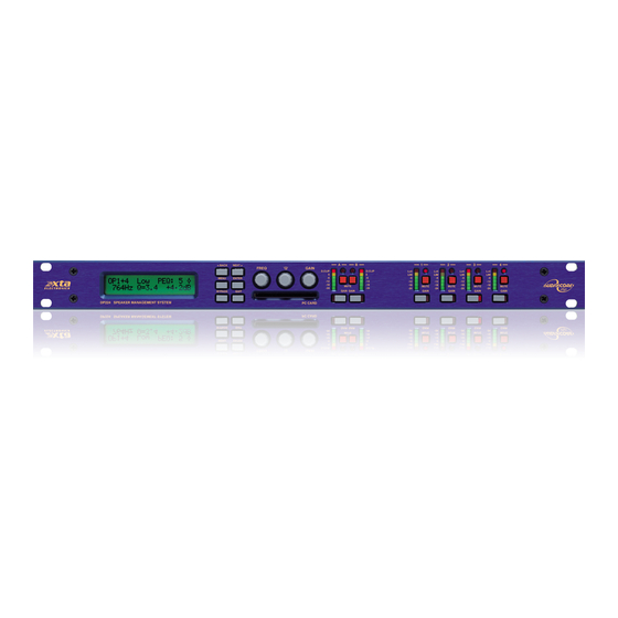
Page 10: Front Panel Familiarisation
Front Panel Familiarisation LCD Screen : shows menu options, channel information, and various parameters as they are adjusted. Next Key : moves forwards through the list of available parameters. Back Key : moves back through the list of available parameters. Menu Key : activates the main menu. -
Page 11: Rear Panel Connections
Rear Panel Connections Power Switch: turns the units mains supply off and on. Mains Fuse: located in a finger-proof holder adjacent to the mains inlet. A spare fuse is also located in this holder. Mains Inlet: connected via a standard IEC socket. External: RS232 standard via a 9 pin D-type connector, for connection to a PC. -
Page 12: Operating The Dp226
Operating the DP226 Note about operation with Windows software. The following operating information covers control of the DP226 via the front panel controls only. Please consult the manual supplied with this software for information regarding computer control. Preliminary Set-up The procedure below should be followed when first installing a DP226. -
Page 13: Dp226 Configurations
DP226 Configurations Introduction To simplify the set-up of the DP226, 5 crossover modes are selectable from the X- over sub-menu. These all have parametric equalisers, high and low pass filters, gain controls, delay and limiters. The following set of diagrams detail how each of the five modes is internally configured. -
Page 14: X 3 Way
2 x 3 way This format feeds input A to outputs 1, 2, and 3 designated low, mid, and high respectively. Input B feeds outputs 4, 5, and 6, as low, mid, and high respectively. Note that this configuration, as with the 2 x 2 way, can have the outputs ganged for stereo operation. -
Page 15: Way
4 way + 2 This format feeds input A to outputs 1, 2, 3, and 4 designated low, lo-mid, hi-mid and high respectively. Outputs 5 and 6 are configured as auxiliaries, with their source being either input B, or the sum or inputs A and B. The choice of pre or post input EQ for the sum signal is only offered if outputs 5 and/or 6 are chosen to feed form the sum. - Page 16 5 way + 1 This format feeds input A to outputs 1, 2, 3, 4, and 5 designated sub, low, lo-mid, hi- mid and high respectively. Output 6 is configured as an auxiliary, with the source being either input B, or the sum or inputs A and B. The choice of pre or post input EQ for the sum signal is only offered if output 6 is chosen to feed form the sum.
-
Page 17: Way
B, this will be why. Note for DP224 Owners: Having four outputs instead of six, the DP224 does not support the same configurations as the DP226. The configurations available for the DP224 are given in Appendix 6, starting on page 58. These configurations have been specially designed to facilitate the use of a DP224 as either half of a stereo 4-way system, or for use on monitors. -
Page 18: Screen Layouts Overview
Screen Layouts Overview Page 18 DP224/6 Operators Manual... -
Page 19: Audio Function Screens
Audio Function Screens Gain Screen To adjust the gain: Use the ‘GAIN’ control. Each input and output has an individual gain screen. The inputs have a range of +6dB to –40dB, adjustable in 0.1dB steps and the outputs have a range of +15dB to – 40dB, again adjustable in 0.1dB steps. -
Page 20: Polarity Screen
Polarity Screen To adjust the polarity: Use the ‘GAIN’ control to switch between + and -. Each output has an independent polarity screen. This gives the flexibility to reverse (flip by 180°) the phase of individual outputs. Note: When the outputs are ganged, the polarity screens remain individual. -
Page 21: Delay Screen
Delay Screen To adjust delay settings: Use the ‘FREQ’ control for coarse control. (1mS steps) Use the ‘Q’ control for fine control. (2.6µS steps) Each input and output has an independent delay time control. Input delay (base delay) is adjustable in 1mS steps. Output delay is adjustable in 2.6µS steps or in 1mS steps giving complete control over driver time alignment. -
Page 22: High And Low Pass Filter Screens
High and Low Pass Filter Screens To adjust HPF/LPF settings: Use the ‘FREQ’ control for the frequency. Use the ‘Q’ control for the slope. Each output has an independent high pass filter and an independent low pass filter. Both filters have a range of selectable slopes, which are Bessel 12dB, 18dB and 24dB, Butterworth 12dB, 18dB and 24dB, and Linkwitz-Riley 24dB. -
Page 23: Parametric Equaliser Screen
Parametric filters are carefully implemented using Double Precision processing. This method is costly in terms of processing power but yields substantial benefits in terms of the DP226's exceptional noise performance and greatly improved low frequency stability. (Note: To show parametric filters in bandwidth (BW) rather than ‘Q’, go into the ‘System sub-menu’, select ’filter Q or BW’, select BW.) -
Page 24: Limiter Screen
Limiter Screen To adjust limiter settings: Use the ‘FREQ’ control to adjust the attack time. Use the ’Q’ control for the release time. Use the ‘GAIN’ control for the limiter threshold. Each output has an independent high performance limiter. All limiters have an attack range of 0.3mS to 90mS, release times are 2, 4, 8, 16 and 32 times the attack time and thresholds range from +22dB to –10dB in 1dB steps. -
Page 25: Menu Selection
Menu Selection The following menu selections are available: Input Memory Sub-menu: Memory Recall – recalls input EQ, input gain, input ganging and base delay. Memory Store – stores the above selection of parameters for inputs. Store to PC Card – stores all the input memories to a PC card as a set. Recall from PC Card –... -
Page 26: Input Memory Sub-Menu
Input Memory Sub-menu Input Memory Recall Press MENU and select the ‘Input Memory Sub-menu’ then ‘Memory Recall’ using the BACK, NEXT and ENTER keys. When the menu is entered, the last recalled memory will be displayed first. Use BACK and NEXT to view the other input memories and press ENTER to load selection. -
Page 27: Input Setup Sub-Menu
Input Setup Sub-menu There are two options in this menu, where applicable, which are: Gang Inputs Gangs A and B inputs so that precise adjustments can be made to both inputs simultaneously. Both GAIN LEDs will light when the inputs are accessed and the LCD will show A+B. -
Page 28: X-Over Sub-Menu
X-over Sub-Menu Load a Xover Loads a stored crossover from the selection available. Enter accepts the selected name and loads immediately. Design a Xover Opens a wizard to design a crossover. Options include format type, ganging of outputs, routing and automatic limiter time constants. The table below outlines which options are available dependant on what type of crossover is chosen for the design. -
Page 29: Security Sub-Menu
Security Sub-Menu After selecting the ‘Security Sub-Menu’ and pressing ENTER, select one of the lock types, after choosing the most appropriate one for your application. As ever, ENTER will confirm your selection. User Specific Upon pressing ENTER to select this type of lock, each parameter group is presented in turn. -
Page 30: Entering The Password To Complete The Locking Operation
A, B, 1, 2, 3, 4, 5 and 6 can be used as a code, as shown below. IMPORTANT - Please note your code! If the security code number is forgotten contact your local XTA sales office. Page 30... -
Page 31: System Sub-Menu
System Sub-Menu System Status Displays unit information including software version and temperature. Curr. Temp. = current temperature in degrees Celsius. Max1. Temp. = maximum temperature this session. Max2. Temp. = maximum temperature ever reached. LCD Contrast Adjusts the LCD contrast from 0 to 100. LED Brightness Adjusts the LED brightness from 1 to 15. -
Page 32: Preset Update
Preset Update This option allows new preset crossover configurations to be uploaded into the unit via a PCMCIA card. Preset configurations are accessible from memory number ten (10) and beyond, in the ‘Load a Xover’ menu option. They may be recalled and edited (if the preset configuration allows editing), but may not be re-saved over the same location. -
Page 33: Interface Sub-Menu
The DP226 has as standard three external interface systems MIDI, RS232 and RS485. This allows complete control over the DP226 via computer (cable or radio) and MIDI ‘Program Change’ command. Setting up the Interface depends on whether the unit is in a single unit system or a multiple unit system. -
Page 34: Multiple Unit System
Multiple Unit System For multiple unit systems one unit is set as a master, this is the unit connected to the computer and or the MIDI controller. This unit should be set-up as for a single unit system. The remaining units should be set as slaves and connected via RS485 XLR connectors in a chain to the master unit. -
Page 35: Aes / Ebu Sub-Menu
AES / EBU Sub-Menu Connection of AES/EBU signals is via the existing rear panel XLR connectors. With the AES/EBU option fitted, AES Receive and Diagnostic modes are provided. Routing Options Selects the input source – either analogue or digital, and similarly the output source, again either analogue or digital. -
Page 36: Remote Gpi Sub-Menu
Remote GPI Sub-Menu In certain circumstances the connection of a computer to a DP226 is both impossible and undesirable, perhaps for reasons of unnecessary complexity and cost. This is where the general purpose interface option becomes useful. It permits the recalling of memories (input, crossover, or both) from a remote location, without the need for expensive interface controllers. -
Page 37: Typical Interface Set-Ups
A typical interface set-up might involve running an RS232 link from laptop or a desktop computer to a DP226 set up as a master unit. The diagram below shows this method of connection, the required menu options are also given. Note that the RS232 cable must be a 1-1 connection type, NOT a null modem cable (which has connections crossed internally). -
Page 38: Rs485 Connection
Midi Connection To use MIDI communications, the DP226 must be configured to receive as a master via its MIDI port. You must have a MIDI card or interface connected to your computer. The setup is shown below. -
Page 39: Operating Notes
Provision is also made for separately isolating each input and output shield pin permanently within the DP226 by breaking the appropriate PCB track, where marked with a box and an arrow next to each XLR connector using a small drill bit or cutter. -
Page 40: Crossover Filter Slopes
It should also be noted that the turnover frequency displayed on the DP226 is the -3dB point for all slopes except 24dB Linkwitz-Riley where the -6dB point is shown. If the -6dB point is... -
Page 41: Output Limiters
Output Limiters High performance digital limiters are provided for each output with control over attack time, release time and threshold level parameters - see page 24 for details. This level of control allows the user to balance the required subjective quality of the limiter against the driver protection requirements. -
Page 42: Setting Accurate Limiter Thresholds
Setting Accurate Limiter Thresholds The limiters built into the DP226 are intended to be used for for loudspeaker driver protection, as opposed to amplifier protection. All modern professional power amplifiers designed for live sound use have their own limiters which are tailored to protecting the amplifier from clipping. - Page 43 First, check the RMS power rating of the speaker system, and its impedance. Look up this value in the table above, using the closest value below the rated power of the speaker system. Note the corresponding ‘dB’ value. Check the gain of your amplifier, which needs to be in ‘dB’. Subtract this gain figure from the dB value obtained from the table to find the required absolute setting for the limiter thresholds.
-
Page 44: Specifications
Specifications Inputs: 2 electronically balanced High and Lowpass Filters Impedance: > 10k ohms. Filters: 1 of each per output. CMRR : >65dB 50Hz - 10kHz. Freq. Range HPF: 10Hz - 16kHz 1/36 octave steps. Outputs: 6 electronically balanced Freq. Range LPF: 35Hz - 22kHz 1/36 octave steps. -
Page 45: Warranty
XTA, are not covered by this warranty. This warranty is exclusive and no other warranty is expressed or implied. XTA is not liable for consequential damages. -
Page 46: Appendices
6.15 0.87 5.48 0.77 4.89 0.69 4.36 0.62 3.88 0.55 3.46 0.49 3.08 0.44 2.75 0.39 2.45 0.35 2.18 0.31 1.95 0.27 1.73 0.24 1.55 Calculation: Vrms = 0.7746 x 10 ^ (dBu + 20) Page 46 DP226 Operators Manual... -
Page 47: Appendix 2: Default X-Over Settings And Names For All Formats
8kHz – 22kHz 20.1Hz – 22kHz LoSub LoMid HiMid High 6 way 15Hz – 80.3Hz 80.3Hz – 149Hz 149Hz – 1kHz 1kHz – 4kHz 4kHz – 10k1Hz 10k1Hz – 22kHz Note: All filters set to 24dB Linkwitz-Riley. DP226 Operators Manual Page 47... -
Page 48: Appendix 3: Equalisation Curves
Appendix 3: Equalisation Curves Parametric Filter Gain Curves Parametric Filter ‘Q’ Curves Parametric Filter High and Low Shelving Responses Page 48 DP226 Operators Manual... - Page 49 Parametric Filter High ‘Q’ – Notch Filter Response High Pass Filter Response Curves Low Pass Filter Response Curves DP226 Operators Manual Page 49...
-
Page 50: Appendix 4: Frequently Asked Questions
This feature permits all settings within one unit to be copied onto a PCMCIA card, and this card, when inserted into another DP226, will set it up to be operationally and audibly identical to the original unit. Settings that are copied are all current audio settings, all crossover memories (9), all input memories (40), and all menu options. - Page 51 Warning 1: that the write protect switch must be turned on again prior to removing the card. If it is not, possible data corruption may occur, resulting in the DP226 not accepting the settings again. Warning 2: All settings in the destination unit (the unit to become the clone) will be overwritten! If this is not acceptable, it might be advisable to create a clone card as described above for the unit, and keep it as a back-up.
-
Page 52: Appendix 5: Additional Information: General Purpose Interface
(xover) memories are recalled or, if desired, both memories at the same time. The mode of operation and memory recall options can be set in the GPI SUB MENU located at the end of the MAIN MENU on the loudspeaker management system. Page 52 DP226 Operators Manual... - Page 53 Individual switches allows “Random Access” of the memories in any order which might be more useful. The type of switch used to build a remote interface is not crucial, but XTA suggest the following as suitable.
- Page 54 Momentary Action Switch (Mem #07) Connection using crossover’s own power supply. Connect pin 5 to pin 9. Momentary Action Switch (Mem #01) +9volts Momentary Action Switch (Mem #07) Connection using external battery supply (9 volt). Page 54 DP226 Operators Manual...
- Page 55 Finally, after pressing ‘ENTER’ to accept these new settings, a final warning message is displayed. Press ‘ENTER’ again to confirm the changes, or press ‘QUIT’ to cancel all changes and revert to the default screen. DP226 Operators Manual Page 55...
- Page 56 As with the ‘Simple’ mode, this need only be a momentary action, but may be latched (permanent) if some form of remote static indication is required. 15-Pin Interface Connections Memory Number Pin13 Pin10 Pin8 Pin4 Pin3 Page 56 DP226 Operators Manual...
- Page 57 9-pin which may be used in exactly the same way as before. The menu options relating to the standard interface have not changed. The port may be used for loading software upgrades, and remote control applications. Note that new software is required to operate the GPI interface itself. DP226 Operators Manual Page 57...
-
Page 58: Appendix 6: Dp224 Crossover Configurations
Appendix 6: DP224 Crossover Configurations Single channel 2 way with 2 auxiliaries, fed from either input B, or the sum of A & B. 2 way crossover, which may be configured to operate in stereo. Page 58 DP226 Operators Manual... - Page 59 3 way crossover, with one auxiliary which may be fed from input B or A & B summed. 4 way crossover. DP226 Operators Manual Page 59...
Need help?
Do you have a question about the DP226 and is the answer not in the manual?
Questions and answers