Table of Contents
Advertisement
Advertisement
Table of Contents

Related Manuals for SEAL 54Base


Summary of Contents for SEAL 54Base
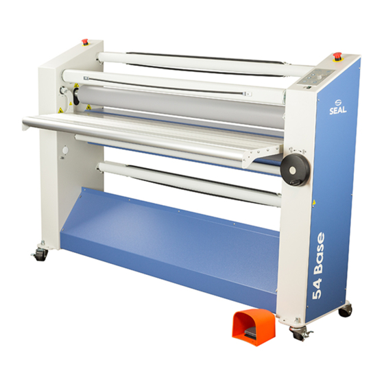
- Page 1 54Base Mounter and Laminator User Manual 977-0080, Rev.C...
- Page 2 For more details on film choice and application solutions refer to the Seal films and adhesives product catalog. THIS MANUAL This manual is intended for the user of the 54Base. Read this manual carefully before starting the machine. This manual contains important information for correct installation, operation and maintenance of the machine.
-
Page 3: Table Of Contents
TABLE OF CONTENTS Warranty and Safety instructions Warranty 1.1.1 Warranty conditions 1.1.2 Warranty period Safety 1.2.1 Safety features 1.2.2 Safety instructions Warnings 1.3.1 General ESD-warning 1.3.2 In this manual 1.3.3 On the machine Description General description Parts identification Process principle Specifications Identification Machine dimensions... - Page 4 Processes and settings 5.5.1 Mounting images or decals 5.5.2 Pre-coating panels 5.5.3 Over-lamination 5.5.4 Single-sided lamination 5.5.5 Decaling Unloading Maintenance Cleaning 6.1.1 Cleaning the silicone covered rollers. Preventive maintenance 6.2.1 Auto-grip shafts Trouble shooting Technical assistance Glossary User Manual 54Base...
-
Page 5: Warranty And Safety Instructions
1. WARRANTY AND SAFETY INSTRUCTIONS Warranty The warranty period and conditions stated in this chapter are merely a summary of the general Seal warranty conditions. For the exact details on the warranty period and conditions for your machine, please contact your dealer. -
Page 6: Safety
When in slow mode the machine is started with the footswitch it will run at low speed so that the operator has both hands free to position and feed new film or image correctly into the machine. User Manual 54Base... -
Page 7: Safety Instructions
1.2.2 Safety instructions Work safely! The owner of the machine is responsible for safe operation of the machine. He therefore is obliged to familiarize operating personnel with the contents of this manual and make them aware of all possible hazards. Do not change, remove or disable the safety facilities. -
Page 8: On The Machine
This symbol is placed on those places where electrostatic charges can be build-up. The machine parts close to the nip and the output material are most likely building up charges. Therefore ESD- symbols are placed on the image guide (2) Figure 1: Warning symbol locations. User Manual 54Base... -
Page 9: Description
2 DESCRIPTION This chapter describes the machine and its operating basics. General description The machine described in this manual is a mono-directional machine dedicated for processing pressure sensitive materials. While feeding through images and the coating films, the two silicone coated main rollers generate the pressure. -
Page 10: Process Principle
The upper main roller can be heated (7) to a fixed temperature of 40 degrees. This is called ‘heat assist’ and can be used to activate the adhesive to flow more evenly and get a better bonding between laminate and image. User Manual 54Base... -
Page 11: Specifications
3 SPECIFICATIONS Identification The machine identification label (example in Figure 4) is located at the bottom of the right-hand cabinet, on the rear side of the machine. This label indicates the model (version) and the power supply requirements. CAUTION: The mains supply must match the values indicated on the machine identification label. -
Page 12: Material Specifications
Optional features: Nip setting: 0–52 0 – 2.05 in. Pressure: 0.3–1.0 N/mm 1.71 – 5.71 lbf/in. Process speed: Maximum m/min 16.4 ft/min Slow mode m/min ft/min Maximum roller temperature: ° C ° F Noise level <70 dB(A) User Manual 54Base... -
Page 13: Installation
4 INSTALLATION WARNING: INSTALLATION MUST BE CARRIED OUT BY SKILLED PERSONNEL. Unpacking At delivery, the machine is packed in a plastic bag to avoid moisture penetration. It is transported in a carton box and is fastened onto a wooden pallet. Place the pallet in a space where there is enough room to roll the machine off from the pallet (approx. -
Page 14: Installation
Turn the leveling feet up completely to prevent them from bending or breaking if accidentally bumping into an obstacle. When moving the machine on rough surfaces or over long distances, use the original pallet and packing material and and move it with a pallet truck or forklift. User Manual 54Base... -
Page 15: Operating
5 OPERATING This chapter describes the function of the controls and indicators, the operating modes, how to set up and operate the machine and a number of applications. The sections in this chapter are placed in a sequence in which the information is needed for laminating processes. - Page 16 Heat-assist (9), ON/OFF switch Switches the heat-assist control ON or OFF. When ON the upper roller will be heated untill it reaches 40 ° C or 104 ° F. Allow ample time to rea ch this temperature. User Manual 54Base...
-
Page 17: Additional Controls
5.1.2 Additional controls Figure 8: Additional controls Emergency stop buttons (1), push and hold button; When pressed the rotation of the rolls is stopped immediately and the button is locked into this stop position. Turn the button to unlock it. Pressing start, reverse or pressing the footswitch starts the process again. -
Page 18: Operating Modes
KEEP CLEAR OF THE REAR SIDE NIP WHEN RUNNING IN REVERSE MODE. When running in reverse, the optical safety device at the front side nip is ignored. An audible tone is heard to warn you for posible danger. The speed is determined by the speed control. User Manual 54Base... -
Page 19: Slow Mode
5.2.2 Slow mode Enter or leave Slow mode by pressing the slow mode button for 1 second. The selection is indicated by the slow mode indication LED. Entering slow mode will not change anything to the current movement of the rollers. In slow mode the rollers can run at normal or at slow mode speed. -
Page 20: Placing Film Rolls
Hold the locking plate (C) with your right hand at (A) in the upper position ((B) is above the shaft). Push the shaft with your left hand, to the right against the spring and remove it from the support at your left-hand side. Now with both hands take out the shaft. User Manual 54Base... -
Page 21: Loading Shaft With Film Rolls
5.3.2 Loading shaft with film rolls The film roll is put on the shaft depending on the type of film and the use in the upper or lower section of the machine. In general pressure sensitive film with release liner (A) is rolled up with the liner (3) and adhesive (2) to the outside of the film (1), whereas film without release liner (C) has its adhesive layer to the inside of the roll. -
Page 22: Webbing
Film without release liner (B) would leave adhesive remains behind on the splitter bar, so this is lead over the splitter bar In the lower section (C), the film is running underneath the splitter bar to avoid adhesive remains staying behind on it. User Manual 54Base... -
Page 23: Using The Upper Section Only
5.4.2 Using the upper section only Figure 14: Webbing upper section. Remove the image guide. Unwind the film from the upper or top unwind roll. • Feed a film without release liner over the splitter bar (A). • Feed a film with release liner underneath the splitter bar (B). Pull the film forward until approximately 10 cm (4 in.) is on the in-feed table. -
Page 24: Presetting The Tension
(top to front) to release the tension. When the film is webbed, it is recommended to set a low tension to each shaft by turning the ring counter-clockwise until you feel some resistance. This will prevent film from unwinding without tension. User Manual 54Base... -
Page 25: Pressure Setting
5.4.5 Pressure setting Thin images When processing thin images (printer output, posters, etc.) pressure is preset when the upper and lower material is webbed. When the leader panel or release board is through the nip, the nip is set to zero and pressure is preset. -
Page 26: Processes And Settings
Removing the release liner completely exposes the adhesive to dirt and dust that will get trapped under the image. With your right hand - keep the image smooth against the upper roller (5), preventing the image from wrinkling. Note: For the best result; do not stop while feeding an image. User Manual 54Base... -
Page 27: Pre-Coating Panels
5.5.2 Pre-coating panels This process is used to coat boards (substrates) with a pressure sensitive mounting film onto which images can be mounted. This process can also be used to create a carrier board. In this case a film with a non-stick surface is used. Note: The mounting film is usually provided with one release liner. -
Page 28: Decaling
Open up the nip and remove the (leader panel and) films from the rollers at the rear. To unload a roll from the shaft: Turn the material roll in the wind-up direction to free the autogrip cords. Take out the autogrip shaft. Remove the material roll from the autogrip shaft. User Manual 54Base... -
Page 29: Maintenance
6 MAINTENANCE Cleaning The machine has to be cleaned regularly. Dirt and dust will have a negative influence on the result of the lamination processes. CAUTION: Do not use abrasive materials for cleaning the machine. This can damage the painted surfaces or the silicone covering of the rollers. Use a damp cloth for cleaning. -
Page 30: Preventive Maintenance
The figures below show some examples where it is caused by the main rollers (3) and gives a possible solution. Wait until a few meters is processed to see results. Pressure too high. Figure 19: Wrinkles due to high pressure. • Decrease the roller pressure a little (5-10%). User Manual 54Base... -
Page 31: Technical Assistance
Pressure too low. Figure 20: Wrinkles due to low pressure. • Increase the roller pressure a little (5-10%). Unwind tension too low. Figure 21: Wrinkles due to low unwind tension. • Increase the unwind tension until the wrinkles (6) in the film on the roller disappear. The lines (7) in the process result will disappear as well. -
Page 32: Glossary
One part of the main element in the machine that performs the actual process (see main rollers). Scrap core An empty cardboard cylinder left over when all material on a roll is used. Webbing Loading the machine with film, so that the machine is ready for processing. User Manual 54Base...
Need help?
Do you have a question about the 54Base and is the answer not in the manual?
Questions and answers