Advertisement
Quick Links
Advertisement

Summary of Contents for CSR Edmonds
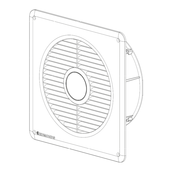
- Page 1 Product Manual ...
- Page 2 Item Checklist Included Parts: QTY: 1 ecoFAN™ Speed Controller Power Supply Speed Controller Fixing Screws 6Gx13mm 6mm Wall Plugs 2 8Gx32mm CSK Screws Product Manual 3 Warranty Document Additional Parts & Tools Required (Not Supplied) Hammer Impact Drill &...
- Page 3 Important Notices and Warnings WARNING: Do not proceed with the installation until you have read the entire instructions, including these warnings. Install at your own risk The installation of this product may be dangerous and includes the potential of personal injury or property damage. Please take care when installing this product and be mindful of risks.
- Page 4 Installation STEP 1 Select appropriate position. Using the fan housing as a guide, mark out a circle/location on the wall. STEP 2—Option A Using an impact drill and 6mm drill bit. Drill holes spaced 3-4 cm around the marked perimeter.
- Page 5 Installation STEP 2—Option B Remove the complete top and bottom shaded bricks. Cut and remove the middle shaded bricks. STEP 3 Clear the hole of debris. 5 ...
- Page 6 Installation STEP 4 Insert the ecoFAN™ into the hole. Make sure it is level and the correct way up. Mark the positions of the mounting holes. The back of the wall grille has a mark to indicate correct orientation. STEP 5 Remove the unit and using a 6mm...
- Page 7 Installation STEP 6 Insert supplied wall plugs into the 6mm drilled mounting holes. Tap into hole with hammer until flush. STEP 7 Using the supplied screws, screw the ecoFAN™ into the wall plugs. 7 ...
- Page 8 Installation—Electrical Connection STEP 1 Connect the speed controller long cable to the ecoFAN™ cable. STEP 2 Connect the Speed controllers short cable to the power supply cable. STEP 3 Connect the power supply to a mains socket. Turn on and check ran funs freely.
- Page 9 Installation—Speed Control Mode The speed controller has 4 operating modes. These are selectable via the 4 position selector on the controller box. To adjust use a 2mm flat screwdriver to turn the switch to the desired position. This can be done whilst the product is running. The default starting position is LO.
- Page 10 Convert From Exhaust to Supply Flow Direction STEP 1 Remove the 4 screws fixing the fan housing to the wall grille. There are arrows on the motor housing that indicate the direction of airflow STEP 2 Reverse the fan housing and using the same screws mount the housing...
- Page 11 Removing Wall grille for Painting STEP 1 Remove the 4 screws fixing the fan housing to the wall grille. The plastic used for the wall grille is suitable for painting with standard spray paints without priming. The surface must be clean before painting.
- Page 12 Technical Data Material: Wall Grille: Plastic (ASA) Fan & Motor Housing: Plastic (PP-TD20) Fan Impeller: Plastic (PA6-GF30) Screws: Stainless Steel (304) Weight: 1.5 kg Electrical: Power Supply Type: Electronic Switching Mode Input: 100-240VAC, 1~, 50/60Hz, 2A Output: 24 VDC Fan Motor: Electronic Commutating (EC) motor Internal Voltage:...
- Page 13 Performance Data & Product Dimensions Sound Pressure Level (SPL) L Flow rate q Max. running power Speed consumption [W] /hr] [dB(A)] LO 32.8 4.4 280 MED 43 11.6 457 HI 53.5 30 734 NOTE—Sound pressure level measured 1m from fan inlet 13 ...
- Page 14 FAQ & Troubleshooting Do I need an electrician to install the ecoFAN™? If you have an available power point that can be reached then no electrician is required. If a power point is unavailable then an electrician will be required to install one. Can I wire it directly into the mains power? No, you must use the supplied power supply and speed controller for the ecoFAN™...
- Page 15 General Enquiries and Support 1300 858 674 Email: Sales@edmonds.com.au Technical Ventilation Enquiries +61 2 8824 0444 Edmonds | business division of CSR Building Products Limited ABN 55 008 631 356 10 Stanton Road, Seven Hills NSW 2147 Australia | www.edmonds.com.au 15 ...
- Page 16 ...


Need help?
Do you have a question about the Edmonds and is the answer not in the manual?
Questions and answers