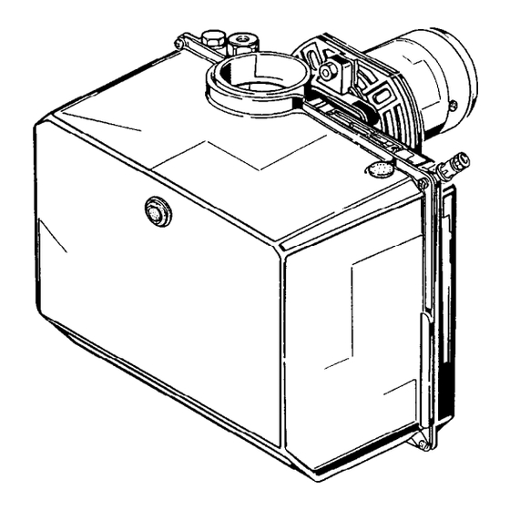
Summary of Contents for Riello G3BF 490T53
- Page 1 Installation, use and maintenance instructions Kerosene burners One stage operation CODE MODEL TYPE 3749053 G3BF 490T53 3749257 G5BF 492T57 3748953 G5BF 489T53 2902136 (6)
-
Page 3: Technical Features
TECHNICAL FEATURES TYPE - Boiler Model 490 T53 – 50 / 70 492T57 – 70 / 90 489 T53 – 90 / 120 Thermal power – output 19 – 35 kW 17 – 42 kW 28 – 60 kW (with air at 20 ° C) 1.6 –... -
Page 4: Mounting The Burner
EQUIPMENT Quantity Description Flexible pipe with nipple Flange with insulating gasket Screw with two nuts for flange Nuts for flange DIMENSIONS Flange Burner ø D5305 TYPE 490 T53 492 T57 489 T53 MOUNTING THE BURNER It is necessary that the insulating gasket (A) is BURNER FIXING placed between the boiler door and the burner flange. -
Page 5: Working Range
WORKING RANGE (as EN 267) 490 T53 Fuel output - kg/h D5425 Thermal power - kW 492 T57 Fuel output - kg/h D5426 Thermal power - kW 489 T53 Fuel output - kg/h Thermal power - kW D5226 2136... -
Page 6: Oil Lines
OIL LINES L meters I. D. I.D. H = Difference of level. meters 8 mm 10 mm L = Max. length of the suction line. I.D. = Internal diameter of the oil pipes. D5307 PRIMING THE PUMP Loosen the plug of the vacuum gauge (4, fig. 1, page 1) and wait until the fuel flows out. - Page 7 BURNER ELECTRICAL WIRING 230V 50Hz WARNING Do not exchange the neutral with the phase. Switch with fuse 6A max. Regulating thermostat Limit thermostat with manual resetting Remote lock-out lamp (230V - 0.5A max.), if required Terminal block of control-box 530SE Valve Black Capacitor...
-
Page 8: Combustion Adjustment
COMBUSTION ADJUSTMENT In conformity with Efficiency Directive 92/42/EEC the application of the burner on the boiler, adjustment and testing must be carried out observing the instruction manual of the boiler, including verification of the CO and CO concentration in the flue gases, their temperatures and the average temperature of the water in the boiler. - Page 9 THE BURNERS LEAVE THE FACTORY SET AT THESE VALUES Pump Comb. head Air damper Pressure adjustment adjustment TYPE Nozzle Set-point Set-point 490 T53 Danfoss 0.60 GPH - 80° H – 492 T57 Danfoss 0.75 GPH - 80° H – 489 T53 Danfoss 1.00 GPH - 80°...
-
Page 10: Electrode Setting
AIR DAMPER ADJUSTMENT The air-output setting can be carried out acting with the rod (2) on the screw (1) that makes the air-damper (3) turn. Further retouchs can be carried out without removing the cover but unscrewing the plug (A) as shown in the figure on the below.


Need help?
Do you have a question about the G3BF 490T53 and is the answer not in the manual?
Questions and answers