Advertisement
Advertisement
Table of Contents

Related Manuals for Haier YR-E12


Summary of Contents for Haier YR-E12
- Page 1 OPERATION & INSTALLATION MANUAL YR-E12 Table of Contents Parts and Functions Operation Malfunction 9-10 Installation Manual For Wire Controller No. 0010573640 Please read this operation manual before using the air conditioner. Please keep this manual carefully and safely.
-
Page 2: Parts And Functions
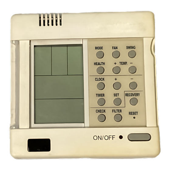
Parts and Functions MODE CLOCK TIMER FAN SPEED CHECK SWING HEALTH RECOVERY FILTER RESET POWER ON/OFF Used for unit start and stop. Cautions: Note: On cooling only unit, heating The above information is the explanation of mode is not available. the displayed information therefore varies with those displayed in actual operation. -
Page 3: Parts And Functions
Parts and Functions [MODE] [AUTO]:Auto operation mode. [FAN ONLY]:air-throwing mode. [COOL]:Cooling operation mode. [DRY]:Dehumidification mode. [HEAT]:Heating operation mode. [HEAT] [TES]:In heating mode, auxiliary electric heater is running. Only when the unit with auxiliary electric heater is in auxiliary electric heating mode, it will display. [FAN] [AUTO]:Auto fan running. -
Page 4: Operation
Operation FAN ONLY OPERATION: 1)Start up operation: press the button of ON/OFF, the system will start up, and will display on LCD. 2)Select MODE: press the MODE button, then you will see in the display section [MODE] switch over in below sequence:[FAN ONLY] [COOL] [DRY] [HEAT] [AUTO] [FAN ONLY]. - Page 5 Operation AUTO operation, COOLING, HEATING and DEHUMIDIFICATION operation 1) Start up operation: press the button of ON/OFF, the system will start up, and will display on LCD. 2) Select MODE: press the MODE button, then you will see in the display section [MODE] switch over in below sequence:[FAN ONLY] [COOL] [DRY]...
- Page 6 Operation Set TIMER operation: Adjust clock: when powered on, for the first time to set timer function, the clock will be adjusted. Press ìCLOCKî button, and set the current clock. Now, ìCLOCKî will flash at the frequency of 2Hz every minute.
- Page 7 Operation FILTER ELEVATING function: (only for the unit with elevating function) In power off state, press [FILTER] for 5 seconds to enter filter elevating set state. In this state, the sign [FILTER] will flash at the frequency of 2Hz. By pressing [+] TEMP [-], filter can go up or down. Press TEMP [+], in timer section [UP] will display, while press TEMP [-], in timer section [DOWN] will display.
-
Page 8: Operation
Operation Query indoor performance state: In normal state, press both buttons of [CHECK] and [FILTER] for 5 seconds, in the set temperature region in the screen, [XX] will display, XX is indoor number, which can be selected by pressing [TEMP] [+] [-]. -
Page 9: Malfunction
Malfunction Code on wired Flash times of indoor Failure description controller receiver board Power LED flashes 1 time Room temp. sensor abnormal Power LED flashes 2 times Indoor coil temp. sensor abnormal Outdoor temp. sensor abnormal Power LED flashes 3 times Power LED flashes 4 times Outdoor coil temp. -
Page 10: Installation Manual For Wire Controller
Installation Manual For Wire Controller 1.Switch over method: wired control master unit/wired control slave unit/remote control unit Control method Wired control master unit Wired control slave unit Remote control unit Socket /jumper CN23 Short circuit Not short circuit Not short circuit CN30 Short circuit Short circuit... -
Page 11: Installation Manual For Wire Controller
Installation Manual For Wire Controller C. Two wired controllers control one indoor unit. The wired controller connected with indoor unit is called master one, the other is called slave one. Master wired controller and indoor unit; master and slave wired controllers are all connected through 3 pieces of polar wire. 3.