Advertisement
Advertisement
Table of Contents

Related Manuals for Hyundai HYBV26


Summary of Contents for Hyundai HYBV26
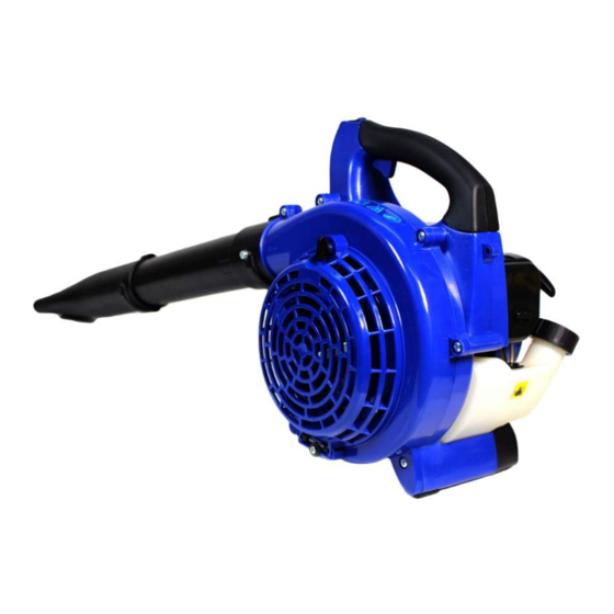
- Page 1 LEAF BLOWER VACUUM Model HYBV26 User Manual...
- Page 2 These procedures are general guidelines only, and are not intended to contravene any safely rules/laws that may be in force in your area. If you have any questions regarding your HYBV26 leafblower vacuum,or if you do not understand something in this...
-
Page 3: Table Of Contents
CONTENTS 1. SAFETY 3 - 8 2. COMPONENT LOCATIONS 3. ASSEMBLY 9 - 11 4. SPECIFICATION 5. FUELING 6. STARTING AND STOPPING THE MACHINE 13 - 15 7. USING THE MACHINE 8. MAINTENANCE 15- 16 9. STORAGE 10. TROUBLESHOOTING 17 - 18 11. -
Page 4: Safety
1. SAFETY. 1.1. The operator of the machine is responsible for and has a duty of care in making sure that the machine is operated safely and in accordance with the instructions in this user manual. Please note the following safety points 1.1.2. -
Page 5: Safety
1.3. Carbon monoxide. 1.3.1. Carbon monoxide is a colourless and odourless gas. Inhaling this gas can cause death as well as serious long term health problems such as brain damage. 1.3.2. The symptoms of carbon monoxide poisoning can include but not limited to the following; 1.3.2.1. - Page 6 1.4.7. Dispose of waste fuels correctly. 1.4.8. Petrol safety. 1.4.8.1. Always fuel and defuel in well-ventilated area. 1.4.8.2. Always wear correct, suitable and fit for purpose Personal Protective Equipment (PPE), suggested items are as follows, but are not limited too. 1.4.8.3.
- Page 7 1.5.6. You must be fit to work with a blower/vacuum: 1.5.6.1. You should not operate the machine if you are not well or physically unable. if you get tired, take a break in good time 1.5.6.2. Do not operate the blower/vacuum if you are under the influence of any substance (drugs, alcohol, etc.) which might impair vision, dexterity or judgment.
-
Page 8: Component Locations
2. COMPONENT LOCATION 1. Recoil starter 2. Fuel cap 3. Trigger 4. Blower tube 2 5. Blower tube 1 6. Fan cover 7. Air filter 8. Vacuum pipes 1&2 9. Choke 10. Spark plug 11. Power switch 12. Collector bag 13. - Page 9 3.2 Attaching collector bag/tube to machine. 3.2.1 Using supplied screwdriver undo the screw (1) and keep safe. 3.2.2 Place end of tube and locate slot (2) onto pin, then push toward machine as far as it can go then turn tube anti-clockwise until the screw-hole (3) is visible through tube.
-
Page 10: Specification
3.4.4 Get end blower tube (4) and locate slot onto pin push toward first tube as far as it can go then turn tube clockwise to lock into position. 3.4.5 To disassemble reverse the above process. 4. SPECIFICATION Model HYBV26 Dimensions (L x W x H ) mm 580 x 355 x 370 Engine type HY1E4FN Displacement 25.4 cc... -
Page 11: Fueling
5. FUELING 5.1 Your engine requires a mixture of petrol and two stroke oil. The quality of these constituents and the mixed ratio has a decisive influence on the function and service life of the engine. 5.2 Use only fresh regular unleaded petrol. 5.3 Use only quality two-stroke engine oil. -
Page 12: Starting And Stopping The Machine
6. STARTING & STOPPING THE MACHINE Never use the machine with any pipes or guards removed. 6.1 To prime the fuel system you must press the primer bulb (1) repeatedly for at least ten pushes. 6.1.1 For COLD engine starting make sure that the choke lever (2) is CLOSED - up position. - Page 13 6.6.1 Disconnect the spark plug lead (1) and use the spark plug wrench (3) to remove the spark plug (2))in a counter-clockwise direction. 6.6.2 If the spark plug is fouled or is soaked with fuel,clean or replace the plug as required.
-
Page 14: Using The Machine
6.8 Stopping the machine. 6.8.1 Allow the engine to cool down by letting it run at idle for 2 to 3 minutes. 6.8.2 Stop the engine by turning the power switch to OFF position. 7. USING THE MACHINE 7.1 General warnings. 7.1.1 When using the machine at higher throttle settings the noise will increase. -
Page 15: Storage
8.2.2 Inspect the filter element. If the filter element is distorted or damaged,replace it with a new one. 8.2.3 Wash the filter element in clean fuel or soapy water,and squeeze or blow dry. 8.2.4 Wash the air cleaner cover in clean fuel and wipe/or blow dry. 8.2.5 Once dry,re-install the filter element and cover,and the tighten the cover retaining screw. -
Page 16: Troubleshooting
10. TROUBLESHOOTING Problem/Scenario Possible cause Solution Spark plug electrode wet Covered with carbon Replace plug Spark plug Damaged insulation Replace insulation Spark gap incorrect Adjust to 0.6~0.7mm Spark plug electrode burned Replace plug The spark plug does not spark Damaged H T Cable Repair or replace Bad coil insulation Replace coil... - Page 17 Problem/Scenario Possible cause Solution The plug or plug wire Firmly replace is loose Piston seized Change the piston Engine stops whilst suddenly during running Spark plug covered in carbon Clean Plug, replace if necessary Engine has run dry of petrol Refill fuel tank with fuel Carburetor clogged Clean the carburetor...
-
Page 18: Exploded Parts Drawings
11. EXPLODED PARTS DRAWINGS. 11.1 Engine Page 18 Rev 2... - Page 19 11.2 Blower/Vacuum (N.B. Parts listing are preceeded with a 2, i.e. part number 1 is part 2.1) Page 19 Rev 2...
- Page 20 11.3 Part lists ENGINE PARTS Item Part Name Item Part Name Spark plug RCJ6Y Gasket, carburetor Bolt M5X20 Carburetor comp Cylinder Choke Handle Gasket, cylinder Cleaner inside cover Ring, piston Choke Piston Bolt ST4×10 Pin, piston 8X28 Air filter element Ring, snap Bolt assy M5X60 8*11*9 Needle bearing...
- Page 21 11.3 Parts list continued 2-22 Pedestal 2-53 Blower tube a 2-23 Fuel tank 2-54 Blower tube b 2-24 Screw m5×20 2-55 Guide, rope 2-25 Lower handle 2-56 Bushing 2-26 Throttle lever shaft 2-57 Plug, lead wire 2-27 Throttle lever handle 2-58 ‘o’...
-
Page 22: Declarations Of Conformity
12. DECLARATIONS OF CONFORMITY 12.1 Genpower Ltd confirms that this Hyundai product conforms to the following CE directives: 12.1.1 2006/42/EC Machinery directive 12.1.2 2004/108/EC EMC directive 12.1.3 2000/14/EC Noise emissions directive 12.1.4 97/68/EC NRMM Emissions directive Page 22 Rev 2... - Page 23 Page 23 Rev 2...
- Page 24 GENPOWER LTD Isaac Way, London Road Pembroke Dock, UNITED KINGDOM, SA72 4RW T: +44 (0) 1646 687 880 F: +44 (0) 1646 686 198 e: info@hyundaipowerequipment.co.uk www.hyundaipowerequipment.co.uk...
Need help?
Do you have a question about the HYBV26 and is the answer not in the manual?
Questions and answers