
Related Manuals for Body Champ VKR 1700


Summary of Contents for Body Champ VKR 1700
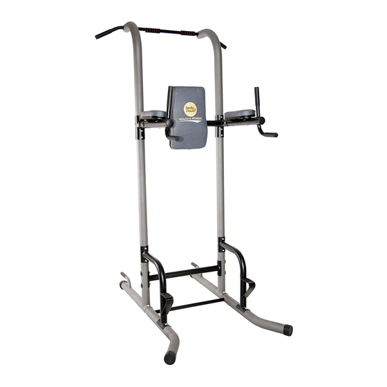
- Page 1 VKR 1700/1010 B o d y C h a m p P o w e r T o w e r * This item is for consumer use only and it is not meant for commercial use. OW NER ’S MA N UAL...
-
Page 2: General Information
General Information Safety Storage and Use Before you undertake any exercise program, Your product is intended for use in clean please be sure to consult with your doctor. dry conditions. You should avoid storage in Frequent strenuous exercise should be excessively cold or damp places as this may approved by your doctor and proper use lead to corrosion and other related problems. -
Page 3: Hardware List
Hardware List The following hardware is used to assemble your unit. Please take a moment to familiarize yourself with these items. Please note some of this hardware is already pre-assembled on the machine. Do not be alarmed if you see parts on this page that are not included in your hardware packet BOLT #18. -
Page 4: Parts Listing
Parts Listing The following parts list describes all of the parts illustrated on the exploded diagram on the following page. Please note, most of these parts are already pre-assembled on your unit. Description 1101L Left Stabilizer 1101R Right Stabilizer 1102 Upright Base Upright 1104... -
Page 5: Exploded Diagram
Exploded Diagram The following diagram is provided to help you familiarize yourself with the parts and hardware that will be used during the assembly process. Please note that not all of the parts and hardware you see here will be used while you are assembling the machine because some of these items are already pre-installed. -
Page 6: Assembly Instructions
Assembly Instructions A s s e m b l y S t e p 1 Hardware Required BOLT With the help of an assistant, attach one Upright Base (# ) to the Left Stabilizer (#1101L) as shown and secure with two Carriage Bolts (#40) and two Nylon Nuts (#25). - Page 7 Assembly Instructions A s s e m b l y S t e p 2 Hardware Required BOLT Insert the Support Crossbar (#133) in the hole located on the inside of Left Stabilizer (#1101L) and secure with one Washer #41 Hex Bolt (M8x70 mm) (#38) and one Hex Bolt (#20).
- Page 8 Assembly Instructions Hardware Required A s s e m b l y S t e p 3 BOLT Attach the lower part of each Support (#1104) to the Left/Right Stabilizers (#1101L/R) by using four Carriage Bolts (#40) and four Nylon Nuts (#25). For now, hand-tighten the Nylon Nuts (#25) on the lower portion to avoid over-tightening and misalignment #40 Carriage Bolt (M8x65 mm) [4 pieces]...
- Page 9 Assembly Instructions Hardware Required A s s e m b l y S t e p 4 BOLT A. Insert the Upright (#103) into the Upright Base (#1102). ENSURE UPRIGHT (#103) THAT THE Please refer to NOTE #1 and NOTE #2 on the illustration! On one side, #41 Hex Bolt (M8x70 mm)
- Page 10 Assembly Instructions A s s e m b l y S t e p 5 Hardware Required BOLT A. Slide the Top Crossbar (#106) between the two Dip Arms (#105R & #105L). Insert two Hex Bolts (#18) through two Washers (#37). Screw one of the Hex Bolts (#18) #18 Hex Bolt (M8x65 mm) through the Dip Arm (#105L) and secure it directly into the Top [4 pieces]...
- Page 11 Assembly Instructions Hardware Required A s s e m b l y S t e p 6 BOLT Attach the Pull -Up Bar (# 1 08) to the two Uprights (#103) by inserting two Hex Bolts (#19) through two Washers (#38) and Pull-Up Bar (#108) , then securing them into the two PLEASE MAKE SURE THE TWO INDENTATIONS ON THE PULL- UP BAR (#108) ARE FACING TOWARD THE UPRIGHTS (#103).
- Page 12 Assembly Instructions A s s e m b l y S t e p 7 Hardware Required Attach the Backrest 13) to the Top Crossbar ( 6) using a BOLT total of two Screws 2) and two Washer 4) as illustrated. DO NOT OVER TIGHTEN THE SCREWS, AS THIS MAY STRIP THE THREAD OR CRACK THE WOOD IN THE BACKREST #22 Screw (M6x20 mm)
- Page 13 Assembly Instructions A s s e m b l y S t e p 8 Hardware Required A. Insert two Screws (#21) and two Washers (#36) through the BOLT bottom of the Right Dip Arm (#105R) as illustrated and secure the Arm Pad (#14) to the Right Dip Arm (#105R).
-
Page 14: Safety And Maintenance
Safety & Maintenance SAFETY & WARNINGS • Make sure all nuts, bolts, and screws are tightened prior to use. • Be sure that all adjustment locking devices and safety devices (if present) are properly engaged prior to use! • Never over-tighten the above-mentioned devices and parts to avoid damage to the unit. •... - Page 15 PLEASE KEEP THESE INSTRUCTIONS FOR FUTURE USE & REFERENCE. DO NOT DISCARD. WARNING: SERIOUS INJURIES AND EVEN DEATH CAN OCCUR IF THE PROPER SAFETY PRECAUTIONS ARE NOT FOLLOWED. The diagram below highlights and reviews many of the important Safety and Warning labels also found on the unit.
- Page 16 Thanks for choosing VKR 1700/1010 Store Location: Version: : 05-08-2012...
Need help?
Do you have a question about the VKR 1700 and is the answer not in the manual?
Questions and answers