Table of Contents
Advertisement
Available languages
Available languages
Quick Links
Sony Corporation
SKC-4065 (SY)
4-538-003-01(1)
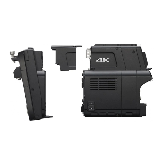
F65 ADAPTOR
SKC-4065
このオペレーションガイドには、事故を防ぐための重要な注意事項と製品の取
り扱いかたを示してあります。このオペレーションガイドをよくお読みのうえ、
製品を安全にお使いください。お読みになったあとは、いつでも見られるとこ
ろに必ず保管してください。
OPERATION GUIDE
[Japanese/English/Chinese]
Printed in Japan
1st Edition
2014.03 32
©2014
電気製品は、安全のための注意事項を守らないと、
火災や人身事故になることがあります。
Advertisement
Chapters
Table of Contents

Related Manuals for Sony SKC-4065


Summary of Contents for Sony SKC-4065
-
Page 1: Operation Guide
F65 ADAPTOR SKC-4065 電気製品は、安全のための注意事項を守らないと、 火災や人身事故になることがあります。 このオペレーションガイドには、事故を防ぐための重要な注意事項と製品の取 り扱いかたを示してあります。このオペレーションガイドをよくお読みのうえ、 製品を安全にお使いください。お読みになったあとは、いつでも見られるとこ ろに必ず保管してください。 OPERATION GUIDE Sony Corporation [Japanese/English/Chinese] Printed in Japan 1st Edition SKC-4065 (SY) 2014.03 32 4-538-003-01(1) ©2014... - Page 2 日本語 安全のために ソニー製品は安全に充分配慮して設計されています。し 警告表示の意味 かし、電気製品はまちがった使い方をすると、火災や感 オペレーションマニュアル 電などにより死亡や大けがなど人身事故につながること および製品では、次のよう があり、危険です。 な表示をしています。表示 事故を防ぐために次のことを必ずお守りください。 の内容をよく理解してから 本文をお読みください。 安全のための注意事項を守る 4 ∼ 6 ページの注意事項をよくお読みください。 この表示の注意事項を守ら ないと、火災や感電などに 定期点検を実施する より死亡や大けがなど人身 長期間安全に使用していただくために、定期点検を実施 事故につながることがあり ます。 することをおすすめします。点検の内容や費用について は、ソニーのサービス担当者または営業担当者にご相談 ください。 この表示の注意事項を守ら ないと、感電やその他の事 故障したら使用を中止する 故によりけがをしたり周辺 ソニーのサービス担当者、または営業担当者にご連絡く の物品に損害を与えたりす ることがあります。 ださい。 注意を促す記号 万一、異常が起きたら • 異常な音、におい、煙が出たら •...
-
Page 3: Table Of Contents
目次 警告................. 4 注意................. 5 その他の安全上のご注意 ............6 使用上のご注意 ...............7 特長 ..................7 F65 と接続する ..............8 F65 から本機を取りはずすには ........10 接続後に必要な設定 ............11 F65 の機能と表示について ..........12 F65 本体から設定できる主な機能 ......... 12 F65 本体で変更される主な機能と表示 ......12 CA4000/BPU4000 の機能と表示について ....14 保守/点検 ................15 CAMERA(カメラ)端子に関するご注意 ....15 CAMERA(カメラ)端子のクリーニング... - Page 4 警告 異常な音、におい、煙 が出たり、画面に異常 があるときは使用をや める 万一、異常な音、におい、 煙が出たり、画面に異常が 発生した場合は、すぐに使 接続ケーブルを傷つけ 用をやめて、ソニーのサー ない ビス担当者または営業担当 者にご連絡ください。 接続ケーブルを傷つける と、火災の原因となること があります。 お手入れの際は接続機 器の電源を切る 電源を入れたままお手入れ をすると、失明の原因にな ることがあります。 外筐を開けたまま使用 しない 外筐を開けたまま使用する と、レーザーによる失明の 原因になることがありま す。 外装を外さない、改造 しない 本機はレーザーを使用して いるため、内部の点検等の 整備を行う場合には、特別 な注意と環境が必要です。 必ずソニーのサービス担当 者にご依頼ください。 警告...
- Page 5 注意 コード類は正しく配置 する 電源コードや接続ケーブル は、足に引っかけると本機 の落下や転倒などによりけ がの原因となることがあり ます。 充分注意して接続・配置し 油煙、湯気、湿気、ほ てください。 こりの多い場所では設 置・使用しない 製品の上に乗らない、 重いものを載せない 上記のような場所に設置す ると、火災や感電の原因と 倒れたり、落ちたり、壊れ なります。 たりして、けがの原因とな ることがあります。 指定された接続ケーブ ルを使用する 使用中、排気口をふさ がない 取扱説明書に記されている 接続ケーブルを使わない 排気口をふさぐと、やけど と、火災や故障の原因とな や故障の原因となることが ることがあります。 あります。 機器への取り付けを正 ファンが止まったまま しく行う の状態で使用しない 本機をカメラに取り付ける ファンモーターが故障する ときは、確実に取り付けて と、やけどの原因となるこ ください。...
-
Page 6: その他の安全上のご注意
撮影時は周囲の状況に その他の安全上の 注意をはらう ご注意 周囲の状況を把握しないま ま撮影を行うと、事故やけ がなどの原因となります。 注意 ここに規定した以外の手順による制御お よび調整は、危険なレーザー放射の被爆 をもたらします。 本機は「クラス 1 レーザー製品」です。 内部レーザーモジュール特性 波長 : 850 nm 発振形態 : パルス変調 レーザー出力 : 4 mW (max)/ch その他の安全上のご注意... -
Page 7: 使用上のご注意
使用上のご注意 特長 本機を寒いところから急に暖かいところ F65 アダプター SKC-4065 は、F65 の に持ち込んだときなど、機器表面や内部 RAW 出力をリアルタイムに伝送し、 に水滴がつくことがあります。これを結 2K(HD)/4K システム接続を可能にするた 露といいます。結露が起きたときは電源 めの CA4000 とのドッキングアダプター を切り、結露がなくなるまで放置し、結 です。 露がなくなってからご使用ください。結 露時のご使用は機器の故障の原因となる F65 8K センサーの解像性能をリアルタ 場合があります。 イムに伝送させることにより、スポーツ 中継などのライブ画像をより高精細に出 力します。臨場感のある画像表現が可能 なだけでなく、HD 画枠でのズーム機能 処理を加えても、画質劣化の少ない画像 を得ることができます。 ご注意 本機をお使いになるには、あらかじめ CA4000 (SKC-PB40 付き ) を本機に組み... -
Page 8: F65 と接続する
ださい。 24P、25P、29.97P、50P、59.94P、 100P、119.88P • カメラシャッター制御 • カメラ ND フィルター制御 • カメラ撮像 Gain 制御 • カメラと CA 間のエラーステータス管 理 CCU からカメラへの給電を中継 SKC-PB40(別売)を装着した CA4000 SKC-4065 CA4000 と F65 の間に、本機に付属の接続コード (SKC-PB40 付き) を装着することにより、CCU からの電 以下の取り付け / 取りはずし手順では、 力を F65 まで供給して動作させることが 上図のように合体した状態のものを「本 できます。 機」と呼びます。... - Page 9 本機の CAMERA 端子からコネク ターキャップを取りはずす。 メモ コネクターキャップをなくさないよ うに、大切に保管しておいてくださ い。 本機の CAMERA(カメラ)端子と F65 の接続端子を合わせて取り付け る。 コネクターキャップを はずしておく 本機を図の向きに合わせる。 2 本機の CAMERA(カメラ)端子 と F65 の接続端子を合わせ、本 機を押し下げる。 こちらを先に合わ せる。 1図のように、本機の下部を F65 の 下部に合わせる。 すきま(太点線部分)が一定 であることを確認する。 F65 と接続する...
-
Page 10: F65 から本機を取りはずすには
メモ コネクターキャップ 上図のようにすきまが一定の場合 は、正しく接続されています。 もし下部のすきまが大きくなった場 合は、取り付けをやり直してくださ い。 図に示す位置を押さえ、確実に押し 込んだ状態で、ドッキングネジで固 定する。 後面の電源供給端子 (12V と 24V の 2 か所)に専用の接続ケーブル (SKC-4065 に付属)を接続します。 接続ケーブルの反対側の端子を F65 の電源入力端子に接続します。 メモ CAMERA(カメラ)端子から取り はずしたコネクターキャップをドッ キングネジに装着しておくことがで きます。 ご注意 F65 から本機を取りはず すには 接続ケーブルをはずす。 F65 と接続する... -
Page 11: 接続後に必要な設定
図に示す位置を押さえ、確実に押し 込んだ状態で、ドッキングネジを緩 める。 接続後に必要な設定 機器 必要な設定 特になし(自動判別) BPU4000 メニュー(Configuration/CHU MODE/CURRENT)で F65 を選 本機を押し上げて取りはずす。 択する。 CA4000 メニュー(Maintenance/CHU このとき、できるだけ F65 に近いと MODE/CURRENT)で F65 を選 ころを持って、図の矢印で示す方向 択する。 に押し上げてください。 a) 最初にシステム構築を行う際に下記のように設 定されている場合は、本機の接続後に動作モー ドを合わせる必要があります。 ・ F65 が HD モードまたは HFR モードに設定 されている。 ・ CA4000/BPU4000 のシステムフォーマット が... -
Page 12: F65 の機能と表示について
F65 本体で変更される主 F65 の機能と表示 な機能と表示 について F65 を本機と接続して使用する場合、一 部の機能や表示が以下のように変更にな ります。 F65 を本機に接続して使用する場合、 F65 にアップグレードキット CBK-65EL サブディスプレイの変更 が装着されている必要があります。 設定ページ 1 また、接続後、F65 はセンサーモジュー *(アスタリスク)が変更後の項目です。 ルとして動作することになり、 SYSTEM FORMAT などの本線設定やネットワー ク接続はできなくなります。 この場合、F65 からの VF 出力と SDI 出 力は、システム出力画像やリターン出力 画像を出力することはできません。 一方、Look や拡大、その他のアシスト 機能は、F65 の単独動作時と同様に、本 1ビデオフォーマット ( 表示のみ )* 線システムに影響を与えることなく独自... - Page 13 5空白 * メニュー 内容 6空白 * Diagnosis 表示や設定値の変更などが 可能です。 設定ページ 3 ビューファインダーのステータ (変更はありません。 ) ス表示の変更 変更後は以下のようになります。 1Assign ボタン 1 2Assign ボタン 2 3Assign ボタン 3 4Assign ボタン 4 5サブディスプレイの明るさ 6自己診断 1システムフォーマット VF メニューの変更 2シャッター開角度 3ND フィルター メニュー 内容 4感度 Camera 下記項目のみ設定値の変更...
-
Page 14: Ca4000/Bpu4000 の機能と表示について
BPU4000 の機 切り換えは、F65 側面パネルの 能と表示について SHUTTER ボタンから操作できます。 (CCU からのカメラ制御では切り換えで きません。 ) F65 を本機に接続して使用する場合、 M. ボタン、または E. ボタンを長押しし CA4000 と BPU4000 も、対応するソフト て切り換えてください。 ウェアバージョンが必要です。 REC ボタンは使用することができませ バージョン 2.0 以降のメニューでは、 ん。 SKC-4065 を使用するためのメニューが M. ボタン 追加されています。 E. ボタン 詳しくは、ソニーのサービス窓口にお問 い合わせください。 ボタン CA4000/BPU4000 の機能と表示について... -
Page 15: 保守/点検
指などで CAMERA(カメラ)端子 の 1 の部分を押して保護シャッ 保守/点検 ターを開き、光コンタクト部分を露 出させる。 シャッター CAMERA(カメラ)端子 に関するご注意 CAMERA(カメラ)端子を使用しない ときは、必ずコネクターキャップをはめ てください。 シャッターが開き、光コンタクト部 分が見えることを確認する。 CAMERA(カメラ)端子 のクリーニング 光コンタクト部分 CAMERA(カメラ)端子が汚れている と、本機と F65 の間の伝送がエラーにな るおそれがあります。F65 の DOCK イ ンジケーターが黄または赤に点灯してい 光ファイバークリーニング用綿棒に る場合は、以下の手順で CAMERA(カ アルコールを付け、光コンタクト部 分全体を優しく 5 回ほど拭く。 メラ)端子をクリーニングしてくださ い。 ご注意 ◆ DOCK インジケーターについては、F65 のオ ペレーションマニュアルをご覧ください。... - Page 16 アダプターカバー(1) +B2.6 × 8 ネジ(12) 仕様 オペレーションガイド(1) 別売り品 一般 デジタルモーションピクチャーカメラ 電源 DC 10.5 V ∼ 17 V (F65,CA4000 より供給) F65 アップグレードキット CBK-65EL ローカル給電時:DC10.5V ∼ カメラシステムアダプター CA4000 カメラパワーブーストキット SKC-PB40 CCU 給電時 : DC14.5V ベースバンドプロセッサーユニット 消費電力 約 4 W(59.94P FAN 最大) BPU4000 動作温度...
- Page 17 English Before operating the unit, please read Egenskaper för intern this manual thoroughly and retain it for lasermodul future reference. Våglängd : 850 nm Strålningens varaktighet: Pulsmodulation Caution Lasereffekt : 4 mW/kanal Use of controls or adjustments or (max) performance of procedures other than Standard : IEC60825-1 those specified herein may result in...
- Page 18 Konan Minato-ku Tokyo, 108-0075 this manual could void your authority to Japan operate this equipment. For EU product compliance: Sony Deutschland GmbH, Hedelfinger All interface cables used to connect Strasse 61, 70327 Stuttgart, Germany peripherals must be shielded in order to...
- Page 19 Verträglichkeit (Störaussendung) et E4 (environnement EMC contrôlé, • EN55103-2: Elektromagnetische ex. studio de télévision). Verträglichkeit (Störfestigkeit) Für die folgenden elektromagnetischen Fabricant: Sony Corporation, 1-7-1 Umgebungen: E1 (Wohnbereich), E2 Konan Minato-ku Tokyo, 108-0075 (kommerzieller und in beschränktem Japon Maße industrieller Bereich), E3 Pour toute question relative à...
- Page 20 For the customers in the U.S.A. SONY LIMITED WARRANTY - Please visit http://www.sony.com/psa/ warranty for important information and complete terms and conditions of Sony’s limited warranty applicable to this product. For the customers in Canada SONY LIMITED WARRANTY - Please visit http://www.sonybiz.ca/solutions/...
- Page 21 Table of Contents Usage Notes ................22 Features .................22 Connecting to the F65 ............23 Removing the Unit from the F65 ........25 Settings Required after Connection ........26 F65 Functions and Displays ..........26 Functions that Can be Performed from the F65 ....26 Changes to F65 Functions and Displays ......27 CA4000/BPU4000 Functions and Displays ......29 Maintenance and Inspections ..........29 Note on the CAMERA Connector ........29...
-
Page 22: Usage Notes
Usage Notes Features If the unit is suddenly taken from a cold to The SKC-4065 F65 Adaptor is a docking a warm location, or if ambient temperature adaptor for the CA4000 that allows suddenly rises, moisture may form on the... -
Page 23: Connecting To The F65
F65, each connected device (i.e., F65, CA4000, BPU4000) and optional device must be of a compatible version. For details, contact your local Sony representative. • When mounting the unit, first mount the F65 on a tripod and secure it such that it does not move. - Page 24 Remove the connector cap from the 2 Align the CAMERA connector of CAMERA connector of the unit. the unit with the dock connector of the F65, and slide the unit down. Store the connector cap in a safe location so that you do not lose it. Align and connect the CAMERA connector of the unit with the F65 connector.
-
Page 25: Removing The Unit From The F65
Press down firmly on the point shown, and loosen the docking screws. Connect the dedicated connection cable (supplied with the SKC-4065) to the power supply connectors (12 V and 24 V) at the rear. Remove the unit by lifting it. -
Page 26: Settings Required After Connection
Attach the connector cap to the F65 Functions CAMERA connector of the unit. and Displays The CBK-65EL Upgrade Kit must be installed on the F65 to operate the F65 with the unit mounted. After mounting, the F65 operates as a sensor module and main line settings, such as SYSTEM FORMAT, and network connections will not be possible. -
Page 27: Changes To F65 Functions And Displays
5 Blank* Changes to F65 Functions 6 Blank* and Displays Settings page 3 When operating the F65 with the unit (No changes occur.) mounted, certain functions and displays will change as follows. Changes to the subdisplay Settings page 1 The asterisks (*) indicate items after changes. - Page 28 Side panel controls Menu Description When the unit is mounted on the F65, Network Cannot be used. switching between the mechanical shutter Diagnosis Display is possible and and the electronic shutter can be performed setting values can be by the SHUTTER buttons on the side panel changed.
-
Page 29: Ca4000/Bpu4000 Functions And Displays
Always attach the connector cap when the required on the CA4000 and BPU4000. CAMERA connector is not in use. Versions 2.0 and later include additional menus for using the SKC-4065. For details, contact your local Sony Cleaning the CAMERA representative. -
Page 30: Specifications
Specifications Shutter General Power supply 10.5 V to 17 V DC (supplied from F65, With the shutter open, check that the CA4000) optical contacts are visible. Local power supply: 10.5 V to 17 V DC Optical contact area CCU power supply: 14.5 V DC Power consumption Approx. -
Page 31: Supplied Accessories
OF THE WARRANTY, OR FOR ANY CA4000 Camera System Adaptor OTHER REASON WHATSOEVER. SKC-PB40 Camera Power Boost Kit • SONY WILL NOT BE LIABLE FOR BPU4000 Base Band Processor Unit CLAIMS OF ANY KIND MADE BY HDCU2000/2500 HD Camera Control Unit USERS OF THIS UNIT OR MADE BY THIRD PARTIES. - Page 32 中文 机型名称:F65 适配器 关于废弃产品的处理 使用产品前请仔细阅读本书,并 请不要将废弃的产品与一般生活 垃圾一同弃置。 请妥善保管。 正确处置废弃的产品有助于避免 注意 对环境和人类健康造成潜在的负 未按照此处规定的程序使用控制 面影响。 器、进行调整或操作可能会导致 具体的处理方法请遵循当地的规 危险的辐射暴露。 章制度。 依据 GB7247.1-2012 《激光产品 的安全 第 1 部分:设备分类、要 求》 ,本装置属于 1 类激光产品 激光二极管特性 波长 : 850 nm 发射持续时间 : 脉冲调制 激光输出功率 : 4 mW/ 通道 (最大)...
- Page 33 目录 使用注意事项 ................34 功能 ....................34 连接 F65 ..................35 从 F65 上拆下本机 ..............37 连接后需要的必要设置 ..............38 F65 功能和显示 ................38 可从 F65 执行的功能 ..............38 F65 功能和显示的变化 ..............38 CA4000/BPU4000 功能和显示 ..........41 维护和检查 ..................41 CAMERA 连接器注意事项 ............41 清洁 CAMERA 连接器 ..............41 规格 ....................42 目录...
-
Page 34: 使用注意事项
(另接 SKC-PB40)相连,并且所有相 连设备 (F65、 CA4000、 BPU4000)和 可选设备的版本必须是相容的。 有关详 细信息,请联系当地 Sony 代表。 可与 SR-R4 便携式存储记录单元轻松 互换 其用于连接摄像机的连接器的结构设计 与 SR-R4 便携式存储记录单元的完全一 致,因而在需要时可轻松进行互换。 24-Gbps 多高速线路传输 利用 Sony 的光 / 电传输模式,用户可以 在不进行压缩的情况下从 F65 传输高容 量 RAW 数据。 具有更佳的容错性 由于具有传输波形特性调整功能,因此 可在不降低图像质量的情况下进行传 输。 使用注意事项 / 功能... -
Page 35: 连接 F65
作 支持在设备之间传输命令;可从 CCU 进行以下摄像机控制。 • 支持多种格式: 23.98P、 24P、 25P、 要使用本机,必须先按如下所示方式将 其连接到 CA4000 (附接 SKC-PB40) 。 29.97P、 50P、 59.94P、 100P、 有关详细信息,请联系当地 Sony 代表。 119.88P • 摄像机快门控制 • 摄像机 ND 滤镜控制 • 摄像机图像增益控制 • 摄像机与 CA 之间的错误状态管理 从 CCU 向摄像机供电 使用本机附送的连接电缆将 F65 与... - Page 36 将本机的 CAMERA 连接器与 F65 连 2 将本机的CAMERA连接器与F65 的对接连接器对准,然后将本 接器对准,然后将它们连接在一 机向下滑动。 起。 取下连接器封盖。 先将此区域对准。 1 按如下方式将本机的底部与 F65 的底部对准。 确认间隙 (粗虚线区域)是均 匀的。 提示 如上图所示,如果间隙是均匀的, 则本机的安装便是正确的。 如果底部间隙更宽,请重新安装。 在图中所示的点处用力按压,然后 拧紧对接螺钉。 按图示方向进行连接。 连接 F65...
-
Page 37: 从 F65 上拆下本机
在图中所示的点处用力按压,然后 提示 松开对接螺钉。 可将从 CAMERA 连接器上取下的 封盖装到对接螺钉处。 连接器封盖 向上提拉本机,将其取下。 将专用连接电缆 (随 SKC-4065 附 提拉时,请尽量抓住离 F65 最近的 送)的一端连接到背面的电源连接 位置,并按照插图中箭头所示方向 器 (12 V 和 24 V)上。 向上提拉。 然后将连接电缆的另一端连接到 F65 的电源输入连接器上。 装上本机 CAMERA 连接器的封盖。 从 F65 上拆下本机 拔下连接电缆。 连接 F65... -
Page 38: 连接后需要的必要设置
连接后需要的必要设置 F65 功能和显示 设备 必要设置 与本机相连后,如欲操作 F65,必须在 无 (自动检测) F65 上安装 CBK-65EL 升级包。 在菜单中选择 F65 BPU4000 (Configuration/CHU 安装后, F65 便如同一个传感器模块, MODE/CURRENT)。 将无法进行主要线路设置 (如 在菜单中选择 F65 CA4000 SYSTEM FORMAT)和网络连接。 (Maintenance/CHU MODE/ CURRENT)。 在这种情况下, F65 的 VF 输出和 SDI 输出将无法输出系统输出图像或返回输 a) 如果在首次连接系统中的设备时指定了以 出图像。... - Page 39 Settings page 3 子显示器的变化 (未出现变化。 ) Settings page 1 星号 (*) 代表发生变化的项目。 1 ASSIGN button 1 2 ASSIGN button 2 3 ASSIGN button 3 4 ASSIGN button 4 1 Video format (无法更改) * 5 Subdisplay brightness 2 Shutter value (无法更改) * 6 Self diagnostics 3 ND filter 4 Master gain (无法更改)...
- Page 40 寻象器中状态指示符的变化 REC 按钮被禁用。 变化后的显示如下。 M. 按钮 E. 按钮 按钮 1 System format 2 Shutter angle 3 ND filter 4 Sensitivity 5 SDI1 look 6 SDI2 look 7 Highlight clip indicator 8 Lens 9 Power supply voltages 0 Message area 可通过 web 浏览器和平板设备 进行的菜单控制...
-
Page 41: Ca4000/Bpu4000 功能和显示
维护和检查 CA4000/BPU4000 功能和显示 CAMERA 连接器注意事项 将本机安装在 F65 上之后,还需要在 不使用 CAMERA 连接器时,请务必盖 CA4000 和 BPU4000 上安装相容的软件 上连接器的封盖。 版本。 2.0 及以上软件版本中包含使用 SKC-4065 的额外菜单。 清洁 CAMERA 连接器 有关详细信息,请联系当地 Sony 代表。 CAMERA 连接器变脏时,本机与 F65 之间出现传输错误的风险会变高。 如果 F65 的 DOCK 指示灯亮起黄色或红色, 请按照如下步骤清洁连接器。 有关 指示灯的详细信息,请参考 DOCK 的... - Page 42 打开遮板后,请确认是否可以看到 规格 光学触点。 光学接触区域 一般规格 电源 10.5 V 至 17 V 直流 (从 F65、 CA4000 供 电) 用光纤清洁棉签蘸一点酒精,然后 本地电源: 10.5 V 至 轻轻擦拭整个光学接触区域 (约五 17 V 直流 次) 。 CCU 电源: 14.5 V 直流 功耗 约 4 W (59.94P FAN 注意...
- Page 43 +B2.6 × 8 螺钉 (12) 操作指南 (1) 可选附件 F65 动态图型数字摄像机 CBK-65EL F65 升级包 CA4000 摄像机适配器 SKC-PB40 摄像机供电设备 BPU4000 基带处理单元 HDCU2000/2500 HD 摄像机控制单元 设计和规格如有更改,恕不另行通知。 注意 • 在使用前请始终确认本机运行正 常。 无论保修期内外或基于任何理由, SONY 对任何损坏概不负责。由于 本机故障造成的利润损失等,无论 是在保修期以内或者以外, SONY 均不作任何赔偿。 • SONY 对本产品用户或第三方的任 何索赔概不负责。 • SONY 对因任何情况导致终止或停 止使用本机相关服务概不负责。 规格...
- Page 44 规格...
- Page 45 本マニュアルを使用することを禁止しま す。 The material contained in this manual consists of information that is the property of Sony Corporation and is intended solely for use by the purchasers of the equipment described in this manual. Sony Corporation expressly prohibits the duplication of any portion of this manual or...