Vertex Standard VX-5500 Operating Manual
Hide thumbs
Also See for VX-5500:
- Operating manual (17 pages) ,
- Specifications (6 pages) ,
- Product manual (28 pages)

Related Manuals for Vertex Standard VX-5500


Summary of Contents for Vertex Standard VX-5500
- Page 1 VX-5500 perating anual POWER Vertex Standard LMR, Inc. 4-6-8 Shibaura, Minato-ku, Tokyo 108-0023, Japan...
- Page 2 After reading it, keep the manual handy for quick reference, in case questions arise later on. We’re glad you joined the Vertex Standard team. Call on us any time, because our busi- ness is communications. Let us help you get your message across.
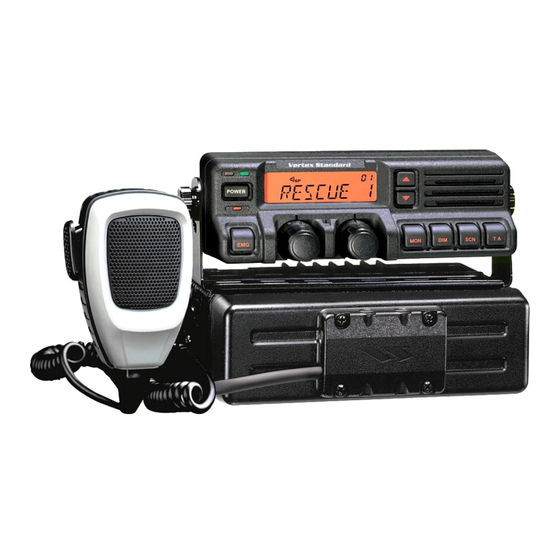
- Page 3 POWER The VX-5500 Series are full-featured FM transceivers designed for flexible mobile and base station business communications in the VHF Low-Band (70/30 Watts: pro- grammable), VHF High-Band (50/25 Watts: programmable) and UHF (45/25 Watts: programmable) Land Mobile Bands. Each model is designed for reliable business com- munications in a wide variety of applications, with a wide range of operating capability provided by its leading-edge design.
- Page 4 Increase the separation between the equipment and receiver. r Connect the equipment into an outlet on a circuit different from that to which the receiver is connected. r Consult the dealer or an experienced radio/TV technician for help. Page 2 VX-5500 Operating Manual...
- Page 5 50 %, dans des configurations typiques de Push-to-Talk. Types d’antenne ayant un gain sup�rieur à 0 dBd sont strictement interdits pour une tilisation avec cet appareil. VX-5500 Operating Manual Page 3...
- Page 6 RF exposure for both workers and the general public. These recom- mended RF exposure levels include substantial margins of protection. All Vertex Standard two-way radios are designed, manufactured, and tested to ensure they meet government-established RF exposure levels. In addition, manufacturers also recommend specific operating instructions to users of two-way radios.
- Page 7 RF exposure and to satisfy compliance requirements. Compliance with RF Exposure Standard Your Vertex Standard two-way radio is designed and tested to comply with a number of national and international standards and guidelines (listed below) regarding human exposure to radio frequency electromagnetic energy.
- Page 8 See the co-located transmitter’s user manual for more details. NOTE: If you are not sure of the rated power of your radio, contact your sales rep- resentative or dealer and supply the radio model number found on the radio model Page 6 VX-5500 Operating Manual...
-
Page 9: Mobile Antenna Installation Guidelines
For additional installation information, see the guidelines for minimum separation distances provided above in the RF Exposure Compliance and Control Guidelines and Operating Instructions section of this document. VX-5500 Operating Manual Page 7... -
Page 10: Compliance And Control Guidelines And Operating Instructions For Mobile Two-Way Radios Installed On Maritime Vessels
For additional installation information, see the guidelines for minimum Separation distances proved above in the RF Exposure Compliance and Control Guidelines and Operating Instructions section of this document. Page 8 VX-5500 Operating Manual... -
Page 11: Mounting Bracket Installation
When installing the VX-5500 transceiver, make sure to plan the installation carefully and leave additional room in the rear of the radio for cabling and accessory connec- tions; in the front of the radio for access, controls, and cabling; and to the sides of the radio so that you may access and install the Hex Head Bolts. - Page 12 VX-5500 transceiver operates only in negative ground electrical systems. Before start- ing the installation, make sure that the ground polarity of the vehicle is correct. Acci- dentally reversing the polarity will not damage the transceiver, but will cause the cable fuses to blow.
- Page 13 Trunk Lid Mount Should be located at the If can not meet the above distance at the trunk lid mount, above distance or more. the antenna must be placed in the center of the roof. VX-5500 Operating Manual Page 11...
-
Page 14: Base Station Installation
Operation of the VX-5500 transceiver from an AC line requires a power supply capable of providing at least 15 Amps continuously at 13.6 Volts DC. Please contact your dealer to select an optimal power supply that satisfy these requirements. - Page 15 When used the VX-5500 transceiver as a base station, the antenna installation must comply with the following requirements in order to ensure optimal performance and compliance with the RF energy exposure limits in the standards and guidelines.
-
Page 16: Controls And Connectors
Receiver Monitor This channel on “H ” List This channel on “S ” List lert This channel on “o ” List Channel Group Number Ption This channel on “auX a/b/c” List 8 Character Alpha-numeric Display Page 14 VX-5500 Operating Manual... -
Page 17: Side Panel
This button can be set up for special applications, such as high/low power selection, monitor, dimmer, talk-around, and call alert function, as determined by your net- work requirements and programmed by your Vertex Standard dealer. VOLUME Knob This knob sets the volume of the receiver. -
Page 18: External Speaker Jack
Caution: Do not connect this line to ground, and be certain that the speaker has ad- equate capability to handle the audio output from the VX-5500. 13.8-V DC Cable Pigtail w/Connector The supplied DC power cable must be connected to this 2-pin connector. Use only the supplied fused cable, extended if necessary, for power connection. -
Page 19: Switching Power On/Off
PTT and wait for the “penalty timer” to expire (if you press the PTT before this timer expires, the timer restarts, and you will have to wait another “penalty” period). VX-5500 Operating Manual Page 17... -
Page 20: Advanced Operation
Programmable Function Button (PF button) The VX-5500 includes the seven Programmable Function Buttons ( PF button). The PF button functions can be customized, via programming by your Vertex Standard dealer, to meet your communications/network requirements. Some features may require the pur- chase and installation of optional internal accessories. - Page 21 Channel Recall ( RCL ) Selectable Tone ( ST ) Speaker ( SP ) ø Squelch Level ( SQL ) Compander ( COMP ) Encryption ( OPT ) ø ø1: for VX-5500L ø2: requires RMK-4000 ø3: requires Encryption Unit VX-5500 Operating Manual Page 19...
-
Page 22: Dual Watch
Because local noise can be particularly troublesome in the VHF Low-Band fre- quency spectrum, the Low-Band version of the VX-5500 includes a Noise Blanker feature, which may be toggled on and off by pressing the assigned PF button of the “Noise Blanker”... - Page 23 Low Power ( LOW ) Press the assigned PF button of the “Low Power” to set the radio’s transmitter to the “Low Power” mode. Press this key again to return to “High Power” operation when in difficult terrain. VX-5500 Operating Manual Page 21...
- Page 24 2. Rotate the CHANNEL selector knob to select the desired level. 3. Press the this key. A tone sounds and the display returns to the normal channel. Page 22 VX-5500 Operating Manual...
-
Page 25: Operation
When you enable this function, the signal-to-noise radio can be improved by reduc- ing the transmitted audio dynamic range. Encryption ( OPT ) When the Voice Scrambler feature is enabled, pressing the assigned PF button of the “Encryption” toggles the Scrambler on and off. VX-5500 Operating Manual Page 23... -
Page 26: Optional Accessories
Radio Programming Cable (for FIF-12) CT-105 Availability of accessories may vary; some accessories are supplied standard per local requirements, others may be unavailable in some regions. Check with your Vertex Standard Dealer for changes to this list. Page 24 VX-5500 Operating Manual... -
Page 27: Warranty Policy
OliCy Vertex Standard warrants, to the original purchaser only, its Vertex Standard manufac- tured communications products against defects in materials and workmanship under normal use and service for a given period of time from the date of purchase. Limited Warranty Details: ... - Page 28 No portion of this manual may be reproduced without the per- mission of Vertex Standard LMR, Inc. Vertex Standard is a trademark of Vertex Standard LMR, Inc. All other trademarks are the property of their respective owners. ©2015 Vertex Standard LMR, Inc.
Need help?
Do you have a question about the VX-5500 and is the answer not in the manual?
Questions and answers