Table of Contents
Advertisement
Advertisement
Table of Contents

Related Manuals for IntelliSense SECURIT 900C


Summary of Contents for IntelliSense SECURIT 900C
- Page 1 INSTALLATION MANUAL SECURIT 900C CONTROL PANEL...
-
Page 2: Table Of Contents
CONTENTS WARNINGS STANDARDS WARRANTY STATEMENT PRODUCT DESCRIPTION AVAILABLE PARTS INTENDED USE FACTORY DEFAULTS INSTALLATION MOUNTING PCB LAYOUT WIRING ELECTRICAL SAFETY NOTICE BATTERY SPECIFIATION TELEPHONE CONNECTIONS DETECTOR CIRCUITS NORMALLY CLOSED DOUBLE BALANCED SINGLE END OF LINE SOUNDERS, SPEAKERS & STROBE WIRING INTERNAL SPEAKER AUXILIARY DC DETECTOR POWER TRIGGER OUTPUT... - Page 3 ZONE MODE COMMUNICATIONS PRIMARY TELEPHONE NUMBER SECONDARY TELEPHONE NUMBER ACCOUNT NUMBER USER CODE 8 DURESS ALARM DOWNLOADER TELEPHONE NUMBER DOWNLOADER ID NUMBER AUTO ANSWER RING COUNT ANSWERING MACHINE DEFEAT COMMUNICATIONS FORMAT HANDSHAKE FORMAT DUAL REPORTING DIAL TYPE LINE FAULT INHIBIT SETTING BELL DELAY PUSH TO SET WHEN TO COMMUNICATE...
-
Page 4: Warnings
1986 which relates to security control equipment. WARRANTY STATEMENT This product is covered by the IntelliSense warranty in force as of the purchase date. A copy may be obtained from the address at the end of this document. PRODUCT DESCRIPTION The Securit 900C is an 8-zone programmable microprocessor control panel with onboard communicator allowing remote upload and download. -
Page 5: Factory Defaults
FACTORY DEFAULTS User Code 1 (master) 1234 User Code 2 - 8 Disabled Engineer Code 9090 Full Set Exit Time 30 Seconds Night Set Exit Time 30 Seconds Entry time 30 Seconds Sounder Ring Time 20 Minutes Bell Trigger Polarity Negative Zone Mode Normally Closed loops... -
Page 6: Installation
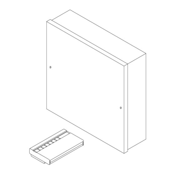
INSTALLATION INSTALLATION Locate the control panel out of sight, such as in a hall, under stairs or in a cupboard where connection is easy and the detector zone and mains cables can be concealed. Avoid areas subject to high temperatures or humidity such as next to a boiler, airing cupboard or conservatory. -
Page 7: Battery Specifiation
BATTERY SPECIFICATION BATTERY SPECIFICATION Maximum battery size is12 V 7.0 Ah. The panel requires a standby battery to be fitted to provide power in the event of mains failure. A valve regulated lead acid battery must be used. Observe the battery polarity. Take great care to connect correctly. -
Page 8: Single End Of Line
SINGLE Programmed as Single End-of-Line END OF LINE Wire a 1kΩ resistor across any unused zones. Only one device should be connected to each alarm circuit. Wire the zone in series with a 1kΩ resistor fitted within the detector. All zone tampers should be wired in series and connected to the Zone Tamp terminals. -
Page 9: Mounting Keypads
MOUNTING A REMOTE KEYPADS MOUNTING REMOTE 1. Choose the keypad location and then mark the holes for mounting. KEYPADS 2. Make sure the cable is run through the backbox. 3. Screw the backbox in the selected position making sure it is not twisted. -
Page 10: Programming Conventions
PROGRAMMING PROGRAMMING CONVENTIONS CONVENTIONS The following conventions are used in the Menu tables: Zone Number – enter key for required zone number. Option Number – enter key for required option number. Two bleeps will follow a successful data entry. REVIEWING The currently programmed setting in menu options can easily be PROGRAMMING reviewed. -
Page 11: Night Set
NIGHT SET ZONE PROGRAMMING MENU 3 NIGHT SET Enter 3-(z)-(o). Enter 3 followed by the key corresponding to the Option Number required from the table below: Enter 0 Not Used Enter 1 Final Exit Enter 2 Keyswitch Enter 3 Full Alarm Enter 4 Walkthrough Enter 5... -
Page 12: Bell Cut-Off Time
BELL CUT-OFF BELL CUT-OFF TIME MENU 43 TIME Enter 43-(o). Enter 4 - 3 followed by the key corresponding to the Option Number required from the table below: Enter 1 1 Minute Enter 2 2 Minutes Enter 3 3 Minutes Enter 4 4 Minutes Enter 5... -
Page 13: Set Inhibit
SET INHIBIT MENU 49 SET INHIBIT Enter 49-(o). Enter 4 - 9 followed by the key corresponding to the Option Number required from the table below: Enter 0 Mains Fail (Default) Enter 1 Low battery Enter 2 Mains fail and Low battery MAINS FAIL WARNING MENU 51 MAINS FAIL Enter 51-(o). -
Page 14: Bell Output Polarity
BELL OUTPUT BELL OUTPUT POLARITY MENU 56 POLARITY Enter 56-(o). Enter 5 - 6 followed by the key corresponding to the Option Number required from the table below: Enter 0 Negative applied (Default) Enter 1 Negative removed ALARM OUTPUT ALARM OUTPUT POLARITY MENU 57 POLARITY Enter 57-(o). -
Page 15: Downloader Telephone Number
DOWNLOADER TELEPHONE NUMBER MENU 65 DOWNLOADER Enter 65 followed by the telephone number. Up to 20 digits are allowed. TELEPHONE End entry by pressing *. Enter # at any position to give a 2 second pause. NUMBER DOWNLOADER ID NUMBER MENU 66 DOWNLOADER Enter 66 Followed by an 8 digit ID number corresponding to the ID ID NUMBER... -
Page 16: Line Fault Inhibit Setting
LINE FAULT LINE FAULT INHIBIT SETTING MENU 73 INHIBIT SETTING Enter 73-(o). Enter 7 - 3 followed by the key corresponding to the Option Number required from the table below: Enter 0 No (Default) Enter 1 Yes, inhibit setting with phone line fault BELL DELAY BELL DELAY BELL DELAY MENU 74... -
Page 17: Fire Alarms
COMMUMICATIONS REPORTING TYPES COMMS REPORTING TYPES COMMUNICATE FIRE ALARMS MENU 81 Enter 81-(o). Enter 8 - 1 followed by the key corresponding to the Option FIRE ALARMS Number required from the table below: Enter 0 No (Default) Enter 1 COMMUNICATE PA ALARMS MENU 82 PA ALARMS Enter 82-(o). -
Page 18: Low Battery & Mains Loss
LOW BATTERY COMMUNICATE LOW BATTERY & MAINS LOSS MENU 88 & MAINS LOSS Enter 88-(o). Enter 8 - 8 followed by the key corresponding to the Option Number required from the table below: Enter 0 No (Default) Enter 1 PERIODIC TEST COMMUNICATE PERIODIC TEST REPORT MENU 89 REPORT Enter 89-(o). -
Page 19: Entry Deviation
The * key can be used to exit the log at any time. VIEWING THE EVENT LOG FROM DOWNLOADER VIEWING EVENT LOG FROM The IntelliSense Downloader software allows the 250 Event Log of the DOWNLOADER panel to be viewed. See the downloader manual for more information. -
Page 20: Restore Factory Programming Defaults
RESTORE RESTORE FACTORY PROGRAMMING DEFAULTS MENU 98 FACTORY Enter 98-1 twice within 5 seconds. DEFAULTS RESTORE RESTORE CODE DEFAULTS CODE To restore the engineer and master user code, disconnect the battery DEFAULTS and remove mains power. Re-apply power and within 5 seconds hold the * and # keys down together until two beeps are heard. -
Page 21: Downloader First Connection
DOWNLOADER - FIRST CONNECTION DOWNLOADER To make a first contact from the downloader to the panel. The panel FIRST requires the following options programmed before a connection from the CONNECTION downloader can be made. The panel must be in “Day Mode” to enable a connection. - Page 22 At the Panel PANEL END - 1. Enter engineer mode by entering 9090 # *, The power LED will FIRST flash. CONNECTION 2. If the control panel programming has not been completed, restore the panel defaults by entering 981 followed by 981 again. 3.
-
Page 23: Fault Finding
FAULT FINDING A selection of common problems and solutions are listed below. Problem Cause Answer Check 24 hr tamper, sounder Tamper will not clear Tamper loop open. tamper and all devices for an with lid on. open tamper loop. Not holding * & # long Be sure to HOLD * &... -
Page 24: Specifications
SPECIFICATIONS Mains Supply Voltage 230 V AC Nominal PSU Output Voltage 13.8 V Nominal Maximum Output Current 1 A (total) AUX. Current 500 mA Max. Panel Quiescent Current 30 mA Mains Fuse 2 A (20 mm) Ceramic HRC Battery Fuse 1 A (20 mm) Anti-surge AUX Fuse 500 mA (20 mm) Anti-Surge... -
Page 25: Quick Programming Guide
Quick Programming Guide The default codes Master 1234 Engineer 9090 To enter Engineer mode CODE ,# * The power LED will flash To Exit Engineer mode The power LED will be constant To review the program Menu 6 - Enter 6 n 0, Where n is the second menu number To review all other menus - Enter Menu No., 00 The keypad display will step through the programmed settings. - Page 26 Menu 6 Default Table 3 Primary telephone number #= 2 sec pause Trigger Output Secondary telephone number #= 2 sec pause 0 V Detector Reset Account number 4 – 6 Digits Enable User 8 as Duress Code Set latch 0=NO, 1=YES Positive Downloader telephone number #= 2 sec pause Downloader ID number...
- Page 27 Menu 0 Default Report ISOLATES 0=NO, 1=YES Invert OPEN / CLOSE 0=NO, 1=YES...
- Page 28 Wiring Diagram SOUNDER CONNECTIONS CONTROL STRB BELL - BELL + BTMP - BTMP -R PANEL ST900C SONADE 2000 STROBE FLASHGUARD STROBE TAMPER SIREN- SUPPLY+ SUPPLY- STARLIGHT 2000 AG 6 & AG 8 NOVA GUARD STROBE 12 V+ 12 V- SPIRIT AU1000 HOLD HOLD STB-...
-
Page 29: Notes
NOTES... -
Page 30: Notes
NOTES... - Page 31 THIS INFORMATION SHOULD BE KEPT EITHER INSIDE THE CONTROL PANEL OR WITH THE INSTALLER. IT CAN BE USED TO REFER TO PROGRAMMING DETAILS WHEN NEEDED. ZONE ZONE USE / LOCATION RESISTANCE Ω Ω Ω Ω Ω Ω Ω Ω Ω Ω Ω...
- Page 32 Telephone +44 (0) 1527 68111 +44 (0) 1527 68222 Technical Support 08457 660533 Local Rate, 9am – 5pm Weekdays (UK Only) Email tech.support@getintellisense.co.uk Sales sales@getintellisense.co.uk www.getintellisense.co.uk © IntelliSense 2002. Printed & Manufactured in the UK. Document No. II1-0900 Rev 1.0...
Need help?
Do you have a question about the SECURIT 900C and is the answer not in the manual?
Questions and answers