Table of Contents
Advertisement
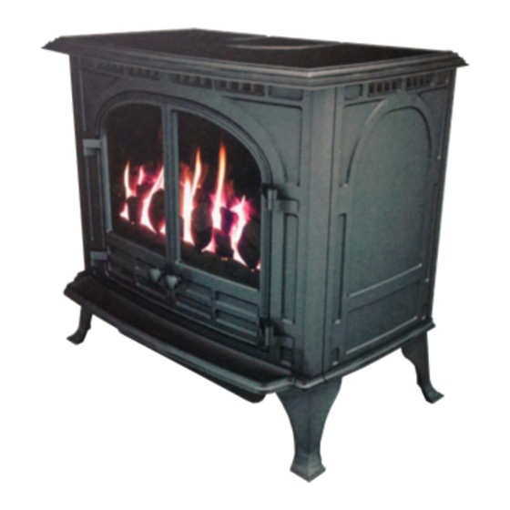
SELECT 6
GAS STOVE
Installation and Servicing Instructions
Please leave this instruction booklet with the user after the
installation is complete. Leave the system ready for
operation and instruct the user in the correct use of the
appliance and operation of its controls.
Please refer to the appliance data plate for the specific
model type.
RevE 18/02/14
Advertisement
Table of Contents

Related Manuals for HS GAS Select 6

Summary of Contents for HS GAS Select 6
- Page 1 SELECT 6 GAS STOVE Installation and Servicing Instructions Please leave this instruction booklet with the user after the installation is complete. Leave the system ready for operation and instruct the user in the correct use of the appliance and operation of its controls.
-
Page 2: Table Of Contents
Attaching the Remote Control Receiver Box .......... 18 SERVICING INSTRUCTIONS ......18 PLEASE READ THESE INSTRUCTIONS CAREFULLY It is important that your stove is correctly installed as HS GAS cannot accept responsibility for any fault arising through incorrect installation. RevE 18/02/14... -
Page 3: Technical Data
TECHNICAL DATA NATURAL GAS Nominal Gas Pressure 20mBar 37mBar Supply Gas Type/Category G20/I G31/I Jet Type/Size 82/380 92/190 Heat Input (Gross) Full 6.5kW 6.4kW 4.2kW 3.7 kW Gas Flow Rate (m Full 0.62 m 0.236 m Class Efficiency Class Countries of Destination GB &... -
Page 4: Installing The Appliance
INSTALLING THE APPLIANCE Pre-Installation Notes 1. Check the stove data plate to establish the gas type required. The data plate can be found on a chain at the top left rear corner of the stove. Before installation check that the local distribution conditions, nature of the gas and pressure, and adjustment of the application are compatible. - Page 5 The chimney or flue system that is to be fitted to the Select 6 gas stove must comply with the current rules in force. (The Select 6 stove is also suitable for other specific class 2 installation arrangements: pre-cast flues, ridge-vent flues and pre-cast chimney block and with the relevant adaption, the appliance will operate in a closure plate type installation.)
-
Page 6: Additional Air Venting (Gb Only)
Additional Air Venting (GB Only) The supply gas heat input into the appliance is nominally less that 7kw, therefore under the directives of the current gas safety installation and use regulations (1995) No additional air vents are required in the room the appliance is situated. Removing the Stove Body HE BODY OF THE STOVE IS HEAVY AKE CARE REMOVING STOVE PARTS... -
Page 7: Removing The Glass
The front section should now be lifted forward and away from the retaining clips (Shown in diagram 6). Diagram 6 Removing the Glass The glass is held in place by 4 fixing clips, 2 at the top and 2 at the bottom. Slightly slacken the lower two fixing screws with a flat blade screwdriver (There is no need to fully remove the screws). -
Page 8: Gas Supply Connections
Gas Supply Connections The appliance is supplied with a 8mm Bundy pipe and a 8mm compression elbow to allow easy connection to the mains gas supply. This supply gas pipe should incorporate a gas service isolation tap that is situated within 1 metre of the application. Diagram 9 shows the 8mm Bundy pipe being fitted to the gas inlet on the valve. -
Page 9: Installation Of The Fire-Bed Into The Stove
3. The mains supply pressure coming into the appliance can also be checked by using Test point ‘B’, shown in diagram 10. Gas Supply Connection (8mm Compression Fitting) Mains/Supply Pressure Test Point (Test Point ‘B’) Diagram 10 Burner Pressure Test Point (Test Point ‘A’) INSTALLATION OF THE FIRE-BED INTO THE STOVE... -
Page 10: Section A - Fitting The 'Coal' Ceramic Matrices
Section A - Fitting the ‘Coal’ Ceramic Matrices : The fire-bed is constructed of 3 ceramic matrices, 4 small ATURAL coals, 10 medium coals and 4 large ‘diamond shaped’ coals. LPG: The fire-bed is constructed of 3 ceramic matrices, 10 small coals, 4 medium coals and 4 large ‘diamond shaped’... -
Page 11: Fitting The Loose Ceramic Coals
3. Place the front ceramic matrix into the fire so that it sits between the middle ceramic matrix and the 2 front tray supports (Steel brackets at the front of the tray) shown in diagram 13. Diagram 13 Fitting the Loose Ceramic Coals 4. - Page 12 5. The second row of coals consists of 4 medium sized coals. They are placed between the large coals so that they sit on the middle ceramic, shown in Diagram 15. Note! The coals must not block the gap between the middle and rear ceramic matrices.
-
Page 13: Section B - Fitting The 'Log' Ceramic Matrices
Section B - Fitting the ‘Log’ Ceramic Matrices The fire-bed is constructed of 3 ceramic matrices and 6 loose logs. A. Place the rear ceramic matrix into the fire as shown in diagram B8. The ceramic should sit on the burner tray top and be placed so that it touches the back of the firebox. -
Page 14: Fitting The Loose Ceramic Logs
Fitting the Loose Ceramic Logs D. Starting with the Y-shaped log, place at the angle shown in diagram B11. The bottom of the log should sit in the cleft on the front ceramic matrix, with the flat underside of it resting on the flat area on the middle matrix. - Page 15 G. The fourth log is the shorter of the two straight logs and sits in the notch on the large log between the trunk and the short branch, as shown in diagram B14. The log should rest on the middle ceramic on the flat section to the right of the large log.
-
Page 16: Test For Spillage
The TTB MUST NOT be removed or ‘bridged out’ for any reason and only genuine HS Gas replacements should be used. Nuisance shut down may occur if the stove is not installed in accordance with the clearance distances set out in page 5. -
Page 17: Operating The Appliance
Operating the Appliance ULL OPERATING INSTRUCTIONS ARE GIVEN IN THE NSTRUCTIONS Fitting the Remote Control (Optional) Fitting the Motor to the Valve Un-screw the cover retaining screw with a small Philips screwdriver (Shown in diagram 18). Prise off the cover at the snap connection with a small flat-bladed screwdriver located on the right hand side of the valve. -
Page 18: Attaching The Remote Control Receiver Box
It must be understood that any recommendations made here are in addition to the standard servicing procedures used by the servicing engineer. 1. A GAS SAFE registered fitter using only original HS GAS parts should carry out servicing. 2. Remove the stove body and glass as described on Page 6 (Removing the Stove Body). -
Page 19: Spares List
SPARES LIST ESCRIPTION UMBER Bundy Tube – Main Burner HG06/032 Bundy Tube – Pilot HG06/033 Bundy Tube – Inlet HG06/034 TTB Switch HG06/200 TTB Leads HG06/201 LPG Burner Injector HG06083 Nat. Gas Burner Injector HG01BU024 Flue Collar HG06/038 Flue Blanking Plate HG06/037 Flue Gasket HG01CE001...
Need help?
Do you have a question about the Select 6 and is the answer not in the manual?
Questions and answers