Table of Contents
Advertisement
Installation Manual
FM200
This product meets and exceeds the requirements of UL 325, the standard which
regulates gate operator safety, by Underwriters Laboratories Inc.
For more information on Mighty Mule's full line of Automatic Gate Openers and Access Controls visit our website at www.mightymule.com
GTO Sales: 800-543-4283 • Fax 850-575-8912
GTO Technical Service 800-453-1236
For 24 hour/day, 7 day/week Technical Service visit http://support.gtoinc.com
For more information on Mighty Mule's full line of Automatic Gate Openers and Access Controls visit www.mightymule.com
Printed in China for GTO Access Systems, LLC.
Copyright
©
2015 GTO Access Systems, LLC rev 12.14.15
Advertisement
Table of Contents

Subscribe to Our Youtube Channel
Related Manuals for GTO Mighty Mule FM200


Summary of Contents for GTO Mighty Mule FM200
- Page 1 GTO Technical Service 800-453-1236 For 24 hour/day, 7 day/week Technical Service visit http://support.gtoinc.com For more information on Mighty Mule’s full line of Automatic Gate Openers and Access Controls visit www.mightymule.com Printed in China for GTO Access Systems, LLC. Copyright ©...
- Page 2 This if you fail to do so GTO Access Systems, LLC gate opener produces a high level of force. shall in no event be liable for direct, indirect,...
-
Page 3: Table Of Contents
Table of Contents PLEASE READ THIS FIRST ......................ii IMPORTANT SAFETY INFORMATION ..................iii TECHNICAL SPECIFICATIONS ...................... x BEFORE YOU BEGIN ......................xi Powering Options ........................xi Check Existing Gate Size and Material ..................xii Check for Proper Gate Installation ....................xii Gate Grounding ........................... -
Page 4: Please Read This First
Our Sales Department will stores. Your store should be able to special order any be glad to give you the name and phone number of a GTO accessory not in stock. If your store cannot special order... -
Page 5: Important Safety Instructions
Because GTO automatic gate openers are only part of the total gate operating system, it is the responsibility of the consumer to ensure that the total system is safe for its intended use. - Page 6 IMPORTANT SAFETY INSTRUCTIONS For the Consumer WARNING: To reduce the risk of injury or death: 2. Make sure the gate has been properly installed and 1. READ AND FOLLOW ALL swings freely in both directions. Repair or replace all INSTRUCTIONS. Failure to meet the requirements set forth in the instruction manual worn or damaged gate hardware prior to installation.
- Page 7 IMPORTANT SAFETY INSTRUCTIONS For the Consumer Entrapment Zones for a proper Pull-To-Open installation: Zone 1 – leading edge of the gate and the fence post. Zone 2 – between the gate and the gate post. Zone 3 – the path of the gate. Zone 4 –...
- Page 8 It is your responsibility to post warning disconnect the operator, contact the GTO Service signs on both sides of your gate. If any of these Department.
- Page 9 IMPORTANT SAFETY INSTRUCTIONS Secondary Means of Protection Against Entrapment As specified by Gate Operator Safety Standard, UL 325 A. One or more contact sensors shall be located at (30A.1.1), automatic gate operators shall have an inherent the leading edge, bottom edge, and post edge, both entrapment sensing system, and shall have provisions for, inside and outside of a vehicular swing gate system.
-
Page 10: Important Safety Information
Warning signs alert people of automatic gate operation and are required when installing the Mighty Mule 200 Automatic Gate Operator. Furthermore, a walk-through gate must be installed if pedestrian traffic is expected near the vehicular gate. We recommend using a Pedestrian Gate Lock. Call the GTO Sales Department at 800-543-4283 for controlled access. - Page 11 Serial No. 9901178 MM200-0000000 XXXXXX GTO Access Systems, LLC - Tallahassee, Florida USA Product identification label (1) installed under rear mount on arm. Warning signs (2 enclosed) to be installed on each side of the gate (3–5 feet above the bottom of the gate)
-
Page 12: Technical Specifications
• The system is powered by a 12 Vdc automotive or marine battery. • Battery charge is maintained by GTO transformer or optional GTO Solar Panels. IMPORTANT: Never use both transformer and solar panel - this will damage the battery and control board. -
Page 13: Before You Begin
[FM121]. Refer to the Solar Panel and Gate Activity chart below. • All low voltage wire used with the GTO Gate Operator must be 16 gauge dual conductor, stranded, direct burial wire [RB509]. Do not run more than 1000 ft. of wire. -
Page 14: Check Existing Gate Size And Material
Before You Begin Check Existing Gate Size and Material • Gate size: Up to 12 feet or up to 300 lbs—See chart • Type of gate material: Vinyl, aluminum, chain link, on page x. farm tube, wrought iron, wood (not recommended for solid surface gates). -
Page 15: Items Included
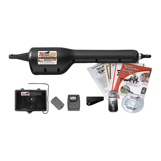
Before You Begin Items Included Operator Transformer Warning Sign Installation Video Closed Position Stop Plate Gate Bracket Control Box Transmitter (1) Post Pivot Bracket Post Bracket 8” Nylon Cable Tie (14) 3/8” Bushing (1) 5/16” Washer (1) 3/8” x 8” Bolt (2) Hairpin Clip (2) 3/8”... -
Page 16: Tools Needed
Before You Begin Tools Needed 3/8” Bit Center Drill Punch 5/16” Bit Pliers Hack Saw Hammer 1/2” wrench Flat Head Screwdriver 9/16” Philips Head wrench Screwdriver Level Wire Small Tape Adjustable Clamps Stripper Flat Head Measure Wrench Items Not Included •... -
Page 17: Gate Operator Installation
GATE OPERATOR INSTALLATION Assemble post bracket parts. Attach opener to gate and post bracket and secure with required hardware. Reinforcement and Gate Bracket Mounting Gate Gate Bracket Bracket Muffler Clamp (not supplied) v in In ju a te ry O C a n KE EP C a u... - Page 18 GATE OPERATOR INSTALLATION v in In ju a te ry O C a n KE EP C a u CL EA e a th R! Ga no t pl ay al lo te m in ga w ch ild re m ov Th is te ar...
-
Page 19: Closed Position Stop Plate Installation
GATE OPERATOR INSTALLATION 6 12 v in In ju a te ry O C a n KE EP C a u CL EA e a th R! Ga no t pl ay al lo te m in ga w ch m ov Th is te ar... -
Page 20: Control Box And Battery Installation
Ped estr Max 1,000 Ft GTO Transformer Mounts Here Use PVC conduit from ground up to control box. Locate power outlet and identify wire path to control box. NOTE: If OUTLET is OUTSIDE use weatherproof cover. -
Page 21: Transformer Wiring Installation
LOCK+ VAR5 LOCK - EDGE ANT SHLD M_BLK M_RED VAR6 PGOK200 Rev. XC VAR2 ON OFF GTO Inc. Ta l l a ha s s ee , FL BATT- BATT+ VAR3 LOCK+ 4” LOCK - Wrong Wrong Correct ANT SHL... -
Page 22: Solar Panel Installation
Wrong Correct ANT SHL M_BLK M_RED PGOK200 Rev. XC VAR2 ON OFF GTO Inc. Tall ah ass ee, FL BATT- BATT+ Screwed into Wire Exposed strands wire insulation of wire Feed 4” of the solar panel wire through strain relief into control box. -
Page 23: Setting Personal Transmitter Code
SETTING PERSONAL TRANSMITTER CODE All GTO transmitters are set to a standard code at the factory and are ready to operate your gate opener. For your safety and security, however, we strongly recommend that you replace the factory setting with your own personal code. -
Page 24: Setting Closed Limit Position
SETTING CLOSED LIMIT POSITION C L O T IM S T A 1 2 0 C 1 5 E D 1 M IN R 20 IC 4 T U S S T A P O W L E D C H G VA R C H G C O M... -
Page 25: Setting Stall Force And Auto Close Time
In c . G T O PGOK200 Rev. XC VAR2 ON OFF GTO Inc. Talla ha ssee, FL BATT- BATT+ Open control box. Turn the “STALL FORCE” arrow in the center of the potentiometer with small flat head screwdriver. Adjust the sensitivity from the MINIMUM position up to the point where the gate operates without obstructing from its own weight or the wind conditions in your area. -
Page 26: Connecting Safety Devices
CONNECTING SAFETY DEVICES Although GTO strongly recommends the use of additional safety devices, we do not endorse any specific brand names. Only use products that are certified and listed to be in compliance with any applicable UL standards (Underwriters Laboratories) and national and regional safety codes. -
Page 27: Control Board Connections
Activation of this input while idle will prevent gate from running. COM: • Common/Negative terminal for accessory devices. LOCK +: Positive terminal to connect GTO electro-mechanical lock. (FM143) LOCK - : Negative terminal to connect GTO electro-mechanical lock. (FM143) rev 12.14.15... -
Page 28: Connecting Accessories
CONNECTING ACCESSORIES GTO Lock Edge Sensor Mighty Mule GTO Photo Beams Push Button Control Blue Black Yellow Shield Mighty Mule Vehicle Sensor Refer to Vehicle Sensor Mighty Mule Keypad manual for additional information if needed. NOTE: Connections are for typical applications. -
Page 29: Maintenance
4 times a year; more frequently if the gates are near a coastal area. TROUBLESHOOTING GUIDE If your gate opener does not function properly after it is installed, use this guide before calling the GTO Service Department. Audible Feedback Symptom... - Page 30 Visual Feedback Symptom Diagnosis Check: Power (green) ON AC or Solar Power Normal Operation Present Power (green) OFF No AC or Solar Power Transformer: • Breaker or GFI • Power at AC outlet. • Output of Transformer. • Voltage on wire at 18 VAC Input Solar: •...
-
Page 31: Repair Service
NOTE: Products returned to GTO without a Return Goods Authorization (RGA) number in LARGE BOLD PRINT on the outside of the package WILL NOT be accepted. Items returned to GTO freight collect WILL NOT be accepted. Items returned without proof of purchase will not be repaired under warranty. -
Page 32: Conversion Chart
Please record the product serial number (located on the right hand side of the control box), and the date and place of purchase in the spaces provided below. Refer to this information when calling GTO for service or assistance with your automatic gate opener. -
Page 33: Accessories
® America’s #1 D-I-Y Gate Opener ACCESSORIES Accessories are Available From Your Retail Store Solar Panel (FM121) The Solar Panel is a 5 watt solar powered battery charger for use with the Mighty Mule 200 gate operator systems. Particularly suited for remote installations, each Solar Panel comes with tubular steel support, mounting clips, wire connectors, and 10 ft. - Page 34 1-800-543-4283! The contents of all material available on this installation manual are copyrighted by GTO Access Systems, LLC (“GTO”), unless otherwise indicated. All rights are reserved by GTO, and content may not be reproduced, downloaded, disseminated, published, or transferred in any form or by any means, except with the prior, written permission of GTO. Any reprinting of GTO publications is by permission only.
- Page 35 Notes NOTES...
- Page 36 ® America’s #1 D-I-Y Gate Opener 3121 Hartsfield Road • Tallahassee, Florida, USA 32303 Telephone GTO Sales: 1-800-543-4283 • Fax (850) 575-8912 or GTO Technical Service: 1-800-543-1236 • Fax (850)575-8950 www.mightymule.com...
Need help?
Do you have a question about the Mighty Mule FM200 and is the answer not in the manual?
Questions and answers