
Related Manuals for MTU 16V2000S56


Summary of Contents for MTU 16V2000S56
-
Page 1: Operating Instructions
Operating Instructions Diesel engine 12V2000S56 16V2000S56 12V2000C66 16V2000C66 12V2000C66R 12V2000S96 16V2000S96 MS150094/02E... - Page 2 All information in this publication was the latest information available at the time of going to print. MTU Friedrichshafen GmbH reserves the right to change, delete or supplement the information provided as and when required.
-
Page 3: Table Of Contents
2.5.1 12/16V 2000 C66 engine data 6.6.2 Fuel prefilter – Differential pressure check 2.5.2 Engine data 12V2000C66R and adjustment of gauge 2.5.3 Engine data 12/16V2000S56 6.6.3 Fuel prefilter – Draining 2.5.4 12/16V 2000 S96 engine data 6.6.4 Fuel prefilter – Flushing 6.6.5 Fuel prefilter –... - Page 4 7 Appendix A 6.15.1 Battery-charging generator drive – Drive belt replacement 7.1 Abbreviations 6.16 Engine Governor 7.2 MTU contact persons/service partners 6.16.1 Engine governor – Overview 6.16.2 Engine governor – Removal 8 Appendix B 6.16.3 Engine governor – Installation 6.16.4 Engine governor plug connections – Check 8.1 Special Tools...
-
Page 5: Safety
Nameplate, model designation or serial number can be found on the product. All EU-certified engines delivered by MTU come with a second nameplate. When operating the machine in the EU: The second nameplate must be affixed in a prominent position as described in the accompanying specifi- cations. - Page 6 The maintenance schedules of the manufacturer must be observed over the entire life cycle of the product. Replacing components with emission labels Emission labels are attached to all MTU engines. These must remain on the engine throughout its operational life.
-
Page 7: Personnel And Organizational Requirements
1.2 Personnel and organizational requirements Organizational measures of the user/manufacturer This manual must be issued to all personnel involved in operation, maintenance, repair, or transportation. Keep this manual handy in the vicinity of the product such that it is accessible to operating, maintenance, repair, and transport personnel at all times. -
Page 8: Transport
Only set down engine on a firm, level surface. Make sure that the consistency and load-bearing capacity of the ground or support surface is adequate. Never set an engine down on the oil pan unless expressively authorized to do so by MTU on a case-to-case basis . -
Page 9: Safety Precautions When Working On The Engine
1.4 Safety precautions when working on the engine Safety regulations prior to maintenance and repair work Have maintenance or repair work carried out by qualified and authorized personnel only. Allow the product to cool down to less than 50 °C (risk of explosion for oil vapors, fluids and lubricants, risk of burning). - Page 10 Never bend lines and avoid damaging lines, particularly the fuel lines. Ensure that all retainers and dampers are installed correctly. Ensure that O-rings are not installed in a slanted/twisted condition. Ensure that all fuel injection and pressurized oil lines are installed with enough clearance to prevent contact with other components.
- Page 11 During hydraulic installation/removal of components, ensure that no persons are in the direct vicinity of the component being pressed. Working with batteries Observe the safety instructions of the battery manufacturer when working with batteries. Gases released from the battery are explosive. Avoid sparks and naked flames. Do not allow battery acids to come into contact with skin or clothing.
-
Page 12: Fire Prevention And Environmental Protection, Fluids And Lubricants, Auxiliary Materials
The safety data sheet may be obtained from the relevant manufacturer or from MTU. Take special care when using hot, chilled or caustic materials. -
Page 13: Compressed Air
Lead • Adopt suitable measures to avoid the formation of lead dust. • Switch on extraction system. • When working with lead or pastes containing lead, avoid direct contact to the skin and do not inhale lead vapors. • Wash relevant areas after contact with lead or lead-containing substances. Compressed air Observe special safety precautions when working with compressed air: •... -
Page 14: Standards For Safety Notices In The Text
1.6 Standards for safety notices in the text DANGER In the event of immediate danger. Consequences: Death, serious or permanent injury! • Remedial action. WARNING In the event of a situation involving potential danger. Consequences: Death, serious or permanent injury! •... -
Page 15: Product Summary
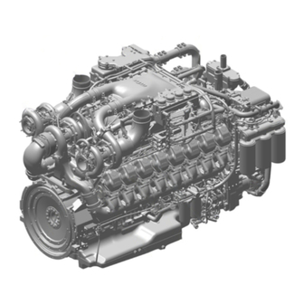
2 Product Summary 2.1 Engine – Overview 12/16 V 2000 C66/S96 This overview also applies to 16 V 2000 C66 and 16 V 2000 S96 engines. 1 Exhaust turbocharger 7 Power supply 13 Valve gear 2 Air intake/air supply 8 Cooling air system 14 Cylinder head 3 EGR cooler 9 Coolant system... - Page 16 Key to the engine model designation Application segment (0, 1, 2,...,9) Design index (0, 1, 2,...,9) 16 | Product Summary | MS150094/02E 2015-05...
-
Page 17: Engine Side And Cylinder Designations
2.2 Engine side and cylinder designations 1 Left engine side (A-side) 3 Right engine side (B-side) 2 Engine free end in accord- 4 Engine driving end in ac- ance with DIN ISO 1204 cordance with (KGS = Kupplungsgegen- DIN ISO 1204 (KS = Kup- seite) plungsseite) Engine sides are always designated (in accordance with DIN ISO 1204) as viewed from driving end (4). -
Page 18: Engine - Main Dimensions
2.3 Engine – Main dimensions Engine model / Dimension Item Engine model / Dimension 12 V 2000 C66/S96 16 V 2000 C66/S96 Length (A) approx. 2028 mm approx. 2378 mm Width (B) approx. 1276.5 mm approx. 1287 mm Height (C) approx. -
Page 19: Firing Order
2.4 Firing order Firing order for 12 / 16 V 2000 C66/S96 engines Firing order Number of cylin- ders 12 V A1-B5-A5-B3-A3-B6-A6-B2-A2-B4-A4-B1 16 V A1-B5-A3-A5-B2-B8-A2-A8-B3-A7-B4-B6-A4-A6-B1-B7 MS150094/02E 2015-05 | Product Summary | 19... -
Page 20: Technical Data
2.5 Technical Data 2.5.1 12/16V 2000 C66 engine data Explanation: DL Ref. value: Continuous power BL Ref. value: Fuel stop power A Design value G Guaranteed value R Guideline value L Limit value, up to which the engine can be operated, without change (e.g. of power setting) N Not yet defined value - Not applicable X Applicable... - Page 21 MODEL RELATED DATA (basic design) Number of cylinders Number of cylinders Cylinder arrangement: V angle Degrees (°) Bore Stroke Cylinder displacement Liters 2.233 2.233 Total displacement Liters 26.80 35.73 Inlet valves per cylinder Exhaust valves per cylinder COMBUSTION AIR / EXHAUST GAS Number of cylinders Charge-air pressure before cylinder bar abs...
- Page 22 Number of cylinders Lube oil operating pressure before engine, warning Lube oil operating pressure before engine, shutdown FUEL SYSTEM Number of cylinders Fuel pressure at engine inlet connection, min. (when engine is -0.5 -0.5 starting) Fuel pressure at engine inlet connection, min. (when engine is run- -0.5 -0.5 ning),...
- Page 23 Number of cylinders Engine surface noise with attenuated intake noise (filter) - BL dB(A) (free-field sound pressure level Lp, 1 m distance, ISO 6798, +2 dB(A) tolerance) Engine surface noise with attenuated intake noise (filter) - BL dB(A) (sound power level LW, ISO 6798+2 dB(A) tolerance) MS150094/02E 2015-05 | Product Summary | 23...
-
Page 24: Engine Data 12V2000C66R
2.5.2 Engine data 12V2000C66R Explanation: DL Ref. value: Continuous power BL Ref. value: Fuel stop power A Design value G Guaranteed value R Guideline value L Limit value, up to which the engine can be operated, without change (e.g. of power settings). N Not yet defined value - Not applicable X Applicable... - Page 25 12V2000C Number of cylinders Number of inlet valves per cylinder Number of exhaust valves per cylinder Standard housing connecting flange (engine main PTO) Coolant system (HT circuit) 12V2000C Number of cylinders Coolant temperature (at engine connection: outlet to cooling equipment) °C Coolant temperature after engine, alarm °C...
- Page 26 General operating data 12V2000C Number of cylinders Cold start capability: air temperature (w/o start aid, w/o preheating) - °C (case A) Firing speed, from Firing speed. to Inclinations, standard oil system (reference: waterline) 12V2000C Number of cylinders Longitudinal inclination, continuous max. driving end down (option: max. Degrees (°) 15 operating inclinations) Longitudinal inclination, continuous max.
- Page 27 12V2000C Number of cylinders Engine surface noise with attenuated intake noise (filter) - BL (free-field dB(A) sound power level Lp, 1 m distance, ISO 6798, +2dB(A) tolerance) Engine surface noise with attenuated intake noise (filter) - BL (sound power dB(A) level LW, ISO 6798+2dB(A) tolerance) MS150094/02E 2015-05 | Product Summary | 27...
-
Page 28: Engine Data 12/16V2000S56
2.5.3 Engine data 12/16V2000S56 Explanation: DL Ref. value: Continuous power BL Ref. value: Fuel stop power A Design value G Guaranteed value R Guideline value L Limit value, up to which the engine can be operated, without change (e.g. of power settings). - Page 29 Number of cylinders Number of inlet valves per cylinder Number of exhaust valves per cylinder Standard housing connecting flange (engine main PTO) Coolant system (HT circuit) Number of cylinders Coolant temperature (at engine connection: outlet to cooling °C equipment) Coolant temperature after engine, alarm °C Coolant temperature after engine, shutdown °C...
- Page 30 Inclinations, standard oil system (reference: waterline) Number of cylinders Longitudinal inclination, continuous max. driving end down (op- Degrees tion: max. operating inclinations) (°) Longitudinal inclination, continuous max. driving end up (option: Degrees max. operating inclinations) (°) Transverse inclination continuous max. (option: max. operating in- Degrees clinations) (°)
-
Page 31: 12/16V 2000 S96 Engine Data
2.5.4 12/16V 2000 S96 engine data Explanation: DL Ref. value: Continuous power BL Ref. value: Fuel stop power A Design value G Guaranteed value R Guideline value L Limit value, up to which the engine can be operated, without change (e.g. of power setting) N Not yet defined value - Not applicable X Applicable... - Page 32 Number of cylinders Compression ratio 16.5 16.5 Inlet valves per cylinder Exhaust valves per cylinder Standard housing connecting flange (engine main PTO) COOLANT SYSTEM (HT circuit) Number of cylinders Coolant temperature (at engine connection: outlet to cooling °C equipment) Coolant temperature after engine, warning °C Coolant temperature after engine, shutdown °C...
- Page 33 GENERAL OPERATING DATA Number of cylinders Cold start capability: air temperature (w/o start aid, w/o preheat- °C ing) - (case A) Firing speed, from Firing speed, to INCLINATIONS, STANDARD OIL SYSTEM (reference: waterline) Number of cylinders Longitudinal inclination, continuous max. driving end down (Op- Degrees tion: max.
-
Page 34: Operation
3.1 Putting the engine into operation after extended out-of-service periods (>3 months) Preconditions ☑ Engine is stopped and starting disabled. ☑ MTU Fluids and Lubricants Specifications (A001061/..) are available. Putting into operation after long out-of-service periods (>3 months) Item Action Engine Depreserve (→... -
Page 35: Putting The Engine Into Operation After Scheduled Out-Of-Service-Period
3.2 Putting the engine into operation after scheduled out-of- service-period Preconditions ☑ Engine is stopped and starting disabled. Putting into operation Item Action Lube oil system Check engine oil level (→ Page 102). Coolant circuit Check engine coolant level (→ Page 112), check charge-air coolant level (→... -
Page 36: Starting The Engine
3.3 Starting the engine Preconditions ☑ Engine with no load. DANGER Rotating and moving engine parts. Risk of crushing, danger of parts of the body being caught or pulled in! • Before cranking the engine with starter system, make sure that there are no persons in the engine's danger zone. -
Page 37: Operational Checks
3.4 Operational checks DANGER Rotating and moving engine parts. Risk of crushing, danger of parts of the body being caught or pulled in! • Only run the engine at low power. Keep away from the engine's danger zone. WARNING High level of engine noise when the engine is running. Risk of damage to hearing! •... -
Page 38: Engine Shutdown
3.5 Engine shutdown Preconditions ☑ Engine is not connected to load. CAUTION Shutting down from full-load operation may cause hot water to escape from the expansion tank. Risk of scalding! • Allow engine to cool down. • Wear protective clothing, protective gloves, and safety goggles / safety mask. NOTICE Stopping the engine when it is running at full load subjects it to extreme thermal and mechanical stress- Overheating of and, therefore, damage to components is possible! -
Page 39: Emergency Engine Stop
3.6 Emergency engine stop CAUTION Shutting down from full-load operation may cause hot water to escape from the expansion tank. Risk of scalding! • Allow engine to cool down. • Wear protective clothing, protective gloves, and safety goggles / safety mask. NOTICE An emergency stop causes extreme stress to the engine plant. -
Page 40: After Stopping The Engine - Putting The Engine Out Of Operation
3.7 After stopping the engine – Putting the engine out of operation Preconditions ☑ MTU Preservation and Represervation Specifications (A001070/..) are available. NOTICE Engine coolant with inadequate freeze protection. Water remaining in the pressure sensors freezes at temperatures below 0 °C. -
Page 41: Plant - Cleaning
3.8 Plant – Cleaning Preconditions ☑ Engine is stopped and starting disabled. ☑ No operating voltage is applied. Special tools, Material, Spare parts Designation / Use Part No. Qty. High-pressure cleaning unit Cleaner (Hakupur 50/136) X00056700 WARNING Compressed air gun ejects a jet of pressurized air. Risk of injury to eyes and damage to hearing, risk of rupturing internal organs! •... -
Page 42: Maintenance
4 Maintenance 4.1 Maintenance task reference table [QL1] The maintenance tasks and intervals for this product are defined in the Maintenance Schedule. The Mainte- nance Schedule is a stand-alone publication. The task numbers in this table provide reference to the maintenance tasks specified in the Maintenance Schedule. -
Page 43: Troubleshooting
5 Troubleshooting 5.1 Troubleshooting Engine does not turn when starter is actuated Component Cause Action Battery Low or faulty Charge or replace (see manufacturer's documentation). Cable connections faulty Check if cable connections are properly secured (see manufacturer's documen- tation). Starter Engine cabling or starter faulty Check cable connections for secure seating ;... - Page 44 Faulty Contact Service. Charge-air temperature too high Component Cause Action Engine coolant Engine coolant treatment incorrect Check (MTU test kit). Intercooler Contaminated Contact Service. Engine room Air-intake temperature too high Check fan; check air inlet/outlet ducts. Charge-air pressure too low...
- Page 45 Blue exhaust gas Component Cause Action Engine oil Too much oil in engine Drain engine oil (→ Page 103). Oil mist fine separator of crankcase Replace (→ Page 76). breather clogged Exhaust turbocharger Faulty Contact Service. Cylinder head Piston rings Cylinder liner White exhaust gas Component...
-
Page 46: Engine Control Unit - Ecu9 Fault Messages
5.2 Engine Control Unit – ECU9 fault messages 5 – HI T-Charge Air Yellow alarm; warning Cause Corrective action Charge-air temperature too high 1. Check coolant cooler and intercooler. (Level 1). 2. Contact Service if no malfunction can be detected. 6 –... - Page 47 23 – LO Coolant Level Red alarm; emergency stop Cause Corrective action Coolant level too low. 1. Check coolant circuit for leaks. Check coolant level in expansion tank, top up as necessary. 2. Contact Service if no malfunction can be detected. 25 –...
- Page 48 44 – LO Coolant Level Intercooler Red alarm; emergency stop Cause Corrective action Intercooler coolant level too low. 1. Check coolant circuit for leaks. 2. Check coolant level in expansion tank, top up as necessary. 3. Contact Service if no malfunction can be detected. 51 –...
- Page 49 65 – LO P-Fuel Yellow alarm; warning Cause Corrective action Fuel inlet pressure too low (Level 1. Check fuel lines for leakage. 2. Drain fuel prefilter (→ Page 93). 3. Replace filter element of fuel prefilter (→ Page 96). 4. Replace fuel filter and, if required, intermediate fuel filter (→...
- Page 50 83 – LO P-Fuel (Common Rail) Yellow alarm; warning Cause Corrective action Rail pressure < set value; HP fuel 1. Check wiring of HP fuel control block. control block faulty or leakage in 2. Check high-pressure system for leaks. HP fuel system. 3.
- Page 51 94 – LO T-Preheat Yellow alarm; warning Cause Corrective action Preheating temperature too low 1. Extend preheating period. (Level 1); coolant temperature too 2. Check preheater. low for engine start. 95 – AL Prelubrication Fault Yellow alarm; warning Cause Corrective action Oil priming fault u Contact Service.
- Page 52 122 – HI T-ECU Yellow alarm; warning Cause Corrective action u Check engine room ventilation. Temperature of the electronics too high. 141 – AL Power too high Yellow alarm; warning Cause Corrective action The average power rate over the last 24 hours of engine operation has exceeded the set maximum value.
- Page 53 184 – AL CAN PU Data Flash Error Yellow alarm; warning Cause Corrective action u Contact Service. A programming error occurred when attempting to copy a received PU data module into the Flash module. 186 – AL CAN1 Bus Off Yellow alarm;...
- Page 54 203 – SD T-Charge Air Yellow alarm; warning Cause Corrective action u Check sensor B9 and wiring, replace as necessary (→ Page 138). Charge air temperature sensor faulty. 205 – SD T-Coolant Intercooler Yellow alarm; warning Cause Corrective action Coolant pressure sensor of u Check sensor B26 and wiring, replace as necessary (→...
- Page 55 220 – SD Level Coolant Water Yellow alarm; warning Cause Corrective action Coolant level sensor faulty. 1. Check sensor F33 and wiring, replace as necessary (→ Page 138). 2. Fault is rectified when electronics are switched back on. 221 – SD P-Diff Lube Oil Yellow alarm;...
- Page 56 230 – SD Crankshaft Speed Yellow alarm; warning Cause Corrective action Crankshaft sensor faulty. 1. Check sensor B13 and wiring, replace as necessary (→ Page 138). 2. Fault is rectified when engine is restarted, contact Service if this is not the case. 231 –...
- Page 57 270 – SD Frequency Input Yellow alarm; warning Cause Corrective action Frequency input faulty. 1. Check speed setting transmitter and wiring, replace as necessary (→ Page 138). 2. Fault is rectified when engine is restarted. 321 – AL Wiring Cylinder A1 Yellow alarm;...
- Page 58 325 – AL Wiring Cylinder A5 Yellow alarm; warning Cause Corrective action Short circuit in cylinder A5 1. Check injector wiring. injector wiring. Result: Misfiring. 2. Rectify injector solenoid valve short circuit (positive to negative) (e.g. by exchanging injectors). 3. Fault is rectified when engine is restarted. 326 –...
- Page 59 331 – AL Wiring Cylinder B1 Yellow alarm; warning Cause Corrective action Short circuit in cylinder B1 1. Check injector wiring. injector wiring. Result: Misfiring. 2. Rectify injector solenoid valve short circuit (positive to negative) (e.g. by exchanging injectors). 3. Fault is rectified when engine is restarted. 332 –...
- Page 60 336 – AL Wiring Cylinder B6 Yellow alarm; warning Cause Corrective action Short circuit in cylinder B6 1. Check injector wiring. injector wiring. Result: Misfiring. 2. Rectify injector solenoid valve short circuit (positive to negative) (e.g. by exchanging injectors). 3. Fault is rectified when engine is restarted. 337 –...
- Page 61 343 – AL Open Load Cylinder A3 Yellow alarm; warning Cause Corrective action Open circuit in cylinder A3 1. Check injector wiring, exclude disruption in solenoid valve (e.g. by injector wiring. Result: Misfiring. injector replacement). 2. Fault is rectified after each working cycle. 344 –...
- Page 62 349 – AL Open Load Cylinder A9 Yellow alarm; warning Cause Corrective action Open circuit in cylinder A9 1. Check injector wiring, exclude disruption in solenoid valve (e.g. by injector wiring. Result: Misfiring. injector replacement). 2. Fault is rectified after each working cycle. 351 –...
- Page 63 356 – AL Open Load Cylinder B6 Yellow alarm; warning Cause Corrective action Open circuit in cylinder B6 1. Check injector wiring, exclude disruption in solenoid valve (e.g. by injector wiring. Result: Misfiring. injector replacement). 2. Fault is rectified after each working cycle. 357 –...
- Page 64 363 – AL Stop Injector Power Stage Red alarm; Self-restoring Cause Corrective action Internal electronic fault, 1. Start Engine Control Unit self-test. electronics possibly faulty. 2. Replace ECU in case of fault; if self-test diagnoses “Electronics OK” check for additional fault messages (e.g. wiring fault). 365 –...
- Page 65 390 – AL MCR exceeded Yellow alarm; warning Cause Corrective action DBR/MCR function: MCR (continuous maximum rate) was exceeded. 400 – AL Open Load Digital Input 1 Yellow alarm; warning Cause Corrective action Line disruption at digital input 1. u Check wiring (→ Page 138). 401 –...
- Page 66 407 – AL Open Load Digital Input 8 Yellow alarm; warning Cause Corrective action u Check wiring (→ Page 138). Line disruption at digital input 8. 408 – AL Open Load Emerg. Stop Input ESI Yellow alarm; warning Cause Corrective action u Check wiring (→...
- Page 67 415 – LO P-Coolant Intercooler Yellow alarm; warning Cause Corrective action Coolant pressure in intercooler 1. Check coolant level in expansion tank, top up as necessary. too low (Level 1). 2. Check coolant circuit for leaks. 3. Check coolant pump. 416 –...
- Page 68 444 – SD U-PDU Yellow alarm; warning Cause Corrective action u Replace Engine Control Unit. Sensor of injector output stage faulty. 445 – SD P-Ambient Air Yellow alarm; warning Cause Corrective action Ambient air pressure sensor u Replace Engine Control Unit (sensor is in the ECU). faulty.
- Page 69 472 – AL Stop SD Red alarm; emergency stop Cause Corrective action u Contact Service. Shutdown channels sensor fault. 474 – AL Wiring FO Yellow alarm; warning Cause Corrective action u Contact Service. Wire break or short circuit at FO channel.
- Page 70 536 – AL Wiring PWM_CM1 Yellow alarm; warning Cause Corrective action u Check wiring to connected device or check connected device Wire break or short circuit on channel PWM_CM1. (actuator/sensor), replace as necessary. 549 – AL Power Cut-Off detected Entered in fault memory only. Cause Corrective action The operating voltage of the...
- Page 71 602 – AL CAN Engine Start Lock Yellow alarm; warning Cause Corrective action Start interlock initiated by plant. 1. Check plant configuration. 2. Restart engine (→ Page 36). 610 – AL Wiring HP Control Block 1 Yellow alarm; warning Cause Corrective action Wire break or short circuit at PWM u Check wiring or HP fuel control block, replace as necessary .
- Page 72 836 – AL Nominal Speed Setting Fail Yellow alarm; warning Cause Corrective action u Check wiring (CAN MD). Active analog speed setting faulty. 851 – AL Extern Start and HD too high Entered in fault memory only Cause Corrective action u Contact Service.
- Page 73 1131 – AL Short Circuit Analog Output 2 Yellow alarm; warning Cause Corrective action u Check wiring. The value output at analog output 2 deviates excessively from the value read back. MS150094/02E 2015-05 | Troubleshooting | 73...
-
Page 74: Task Description
6 Task Description 6.1 Engine 6.1.1 Engine – Barring manually Preconditions ☑ Engine is stopped and starting disabled. Special tools, Material, Spare parts Designation / Use Part No. Qty. Engine barring gear F6783914 Ratchet with extension F30006212 DANGER Rotating and moving engine parts. Risk of crushing, danger of parts of the body being caught or pulled in! •... -
Page 75: Engine - Barring With Starting System
6.1.2 Engine – Barring with starting system DANGER Unguarded rotating and moving engine components. Risk of serious injury – danger to life! • Before barring or starting the engine, ensure that nobody is in the danger zone. • After working on the engine, check that all protective devices have been reinstalled and all tools re- moved from the engine. -
Page 76: Crankcase Breather
6.2 Crankcase Breather 6.2.1 Crankcase breather – Oil mist fine separator replacement Preconditions ☑ Engine is stopped and starting disabled. Special tools, Material, Spare parts Designation / Use Part No. Qty. Engine oil Oil mist fine separator (→ Spare Parts Catalog) O-ring (→... -
Page 77: Valve Drive
6.3 Valve Drive 6.3.1 Valve clearance – Check and adjustment Preconditions ☑ Engine is stopped and starting disabled. ☑ Engine coolant temperature is max. 40 °C. ☑ Valves are closed. Special tools, Material, Spare parts Designation / Use Part No. Qty. -
Page 78: Valve Clearance Adjustment
Checking valve clearance at two crankshaft positions Check TDC position of piston in cylinder A1: • If the rocker arms are unloaded on cylinder A1, the piston is in firing TDC. • If the rocker arms are loaded on cylinder A1, the piston is in overlap TDC. Check valve clearance with cold engine: •... - Page 79 Insert feeler gauge between valve bridge and rocker arm to verify that the gauge just passes through the gap. Result: If not, adjust valve clearance again. Final steps Install plug screw and tighten. Remove barring device. Install cylinder head cover (→ Page 80). MS150094/02E 2015-05 | Task Description | 79...
-
Page 80: Cylinder Head Cover - Removal And Installation
6.3.2 Cylinder head cover – Removal and installation Preconditions ☑ Engine is stopped and starting disabled. Special tools, Material, Spare parts Designation / Use Part No. Qty. Torque wrench, 8–40 Nm F30043446 Ratchet F30027340 Gasket (→ Spare Parts Catalog) Preparatory steps On cylinder head covers with crankcase breather: Loosen clamps. -
Page 81: Injector
6.4 Injector 6.4.1 Injector – Replacement Special tools, Material, Spare parts Designation / Use Part No. Qty. Injector (→ Spare Parts Catalog) Injector – Replacement Remove injector and install new one (→ Page 82). MS150094/02E 2015-05 | Task Description | 81... -
Page 82: Injector - Removal And Installation
6.4.2 Injector – Removal and installation Preconditions ☑ Engine is stopped and starting disabled. Special tools, Material, Spare parts Designation / Use Part No. Qty. Installation device F6790085 Puller F6790636 Fuel suction device F30378207 Torque wrench, 1–5 Nm F30452774 Torque wrench, 20–100 Nm F30026582 Ratchet F30027340... - Page 83 Removing injector Remove fuel line (1). Unscrew union nut (2). Pull off pressure pipe neck (3). Extract fuel from the exposed bores using the suction device. Loosen terminals (arrow) on injector and pull off terminal lugs. Remove gasket. Remove screw (3). Note: Screw (3) must be used only once.
- Page 84 Installing injector Remove all covers before installation. Clean sealing surface on cylinder head and protective sleeve. Apply grease to sealing ring on injector (1). Note: Always use the installation device or the hold- down clamp to press injector (1) into cylinder head.
- Page 85 Use torque wrench to tighten screw (3) for hold-down clamp (2) to specified tightening torque. Name Size Type Lubricant Value/Standard Screw Tightening torque (Engine oil) 40 Nm +4 Nm Using a torque wrench, tighten union nut (2) on pressure pipe neck (3) to specified torque. Name Size Type...
- Page 86 Tighten union nut of fuel line (1) on pressure pipe neck (2) to specified tightening torque using a torque wrench. Name Size Type Lubricant Value/Standard Union nut Tightening torque (Engine oil) 37 Nm +3 Nm Fitting gasket and connecting injector Place gasket in correct position onto cylinder head.
-
Page 87: Fuel System
6.5 Fuel System 6.5.1 HP fuel line and pressure pipe neck – Replacement Preconditions ☑ Engine is stopped and starting disabled. Special tools, Material, Spare parts Designation / Use Part No. Qty. Torque wrench, 20–100 Nm F30026582 Ratchet adapter F30027340 Adapter F30006234 Plug-in open-end wrench, 19 mm... - Page 88 Use torque wrench to tighten thrust screw (4) to specified tightening torque. Name Size Type Lubricant Value/Standard Screw Tightening torque 40 Nm ±5 Nm Coat mating face between union nut and HP fuel line, ball seal and thread on both ends of the new HP fuel line (2) with engine oil.
-
Page 89: Fuel System - Venting
6.5.2 Fuel system – Venting Preconditions ☑ Engine is not connected to load. Fuel system – Venting Note: The fuel system can only be vented with the engine running. Start engine (→ Page 36). Operate the engine until it runs smoothly. MS150094/02E 2015-05 | Task Description | 89... -
Page 90: Fuel - Draining
6.5.3 Fuel – Draining Preconditions ☑ Engine is stopped and starting disabled. WARNING Fuels are combustible and explosive. Risk of fire and explosion! • Avoid open flames, electrical sparks and ignition sources. • Do not smoke. • Wear protective clothing, protective gloves, and safety glasses / facial protection. WARNING Liquid or gaseous media, e.g. -
Page 91: Fuel Filter
6.6 Fuel Filter 6.6.1 Fuel filter – Replacement Preconditions ☑ Engine is stopped and starting disabled. Special tools, Material, Spare parts Designation / Use Part No. Qty. Filter wrench F30379104 Diesel fuel Easy-change filter (→ Spare Parts Catalog) WARNING Fuels are combustible. Risk of fire and explosion! •... -
Page 92: Fuel Prefilter - Differential Pressure Check And Adjustment Of Gauge
6.6.2 Fuel prefilter – Differential pressure check and adjustment of gauge DANGER Rotating and moving engine parts. Risk of crushing, danger of parts of the body being caught or pulled in! • Only run the engine at low power. Keep away from the engine's danger zone. WARNING High level of engine noise when the engine is running. -
Page 93: Fuel Prefilter - Draining
6.6.3 Fuel prefilter – Draining Preconditions ☑ Engine is stopped and starting disabled. Special tools, Material, Spare parts Designation / Use Part No. Qty. Diesel fuel Gasket (→ Spare Parts Catalog) WARNING Fuels are combustible and explosive. Risk of fire and explosion! •... -
Page 94: Fuel Prefilter - Flushing
6.6.4 Fuel prefilter – Flushing Preconditions ☑ Engine is stopped and starting disabled (only in the case of single fuel prefilter). Special tools, Material, Spare parts Designation / Use Part No. Qty. Fuel Sealing (→ Spare Parts Catalog) DANGER Rotating and moving engine parts. Risk of crushing, danger of parts of the body being caught or pulled in! •... - Page 95 Fuel prefilter – Flushing Note: Only in the case of double fuel prefilter: Cut out contaminated filter. 1 Left filter cut in 2 Right filter cut in Open vent plug (5) of filter to be flushed. Unlock drain cock (6) by pressing toggle, open it and drain fuel.
-
Page 96: Fuel Prefilter - Filter Element Replacement
6.6.5 Fuel prefilter – Filter element replacement Preconditions ☑ Engine is stopped and starting disabled (only in the case of single fuel prefilter). Special tools, Material, Spare parts Designation / Use Part No. Qty. Fuel Filter element (→ Spare Parts Catalog) Gasket (→... - Page 97 Open vent plug (5) of contaminated filter. Unlock drain valve (6) by pressing toggle and open. Drain water and contaminants from the filter. Close drain valve (6). Remove screws securing cover and take off cover (2). Remove spring housing (4) and filter ele- ment (3).
-
Page 98: Air Filter
6.7 Air Filter 6.7.1 Air filter – Replacement Preconditions ☑ Engine is stopped and starting disabled. Note: Component is genset manufacturer's or vehicle manufacturer's scope of supply. Air filter – Replacement Perform tasks according to manufacturer's specifications. 98 | Task Description | MS150094/02E 2015-05... -
Page 99: Air Intake
6.8 Air Intake 6.8.1 Service indicator – Check See manufacturer's documentation. MS150094/02E 2015-05 | Task Description | 99... -
Page 100: Exhaust Gas Recirculation
6.9 Exhaust Gas Recirculation 6.9.1 Exhaust gas recirculation flaps – Overview 100 | Task Description | MS150094/02E 2015-05... -
Page 101: Exhaust Gas Circulation - Checking Flap Operation
6.9.2 Exhaust gas circulation ‒ Checking flap operation Preconditions ☑ Engine is stopped and starting disabled. WARNING Component is hot. Risk of burning! • Wear protective gloves. Checking exhaust flap operation For installation position of exhaust flaps, refer to overview (→ Page 100). Check operability and ease of movement of exhaust flaps and control linkage by moving the assembly at the points (arrowed) shown... -
Page 102: Lube Oil System, Lube Oil Circuit
6.10 Lube Oil System, Lube Oil Circuit 6.10.1 Engine oil – Level check Preconditions ☑ Engine is stopped and starting disabled. Oil level check prior to engine start Withdraw oil dipstick from guide tube and wipe it. Insert oil dipstick into guide tube up to the stop, withdraw after approx. -
Page 103: Engine Oil - Change
6.10.2 Engine oil – Change Preconditions ☑ Engine is stopped and starting disabled. ☑ Engine is at operating temperature. ☑ MTU Fluids and Lubricants Specifications (A001061/..) are available. Special tools, Material, Spare parts Designation / Use Part No. Qty. Engine oil Sealing ring (→... -
Page 104: Oil Filtration / Cooling
6.11 Oil Filtration / Cooling 6.11.1 Engine oil filter – Replacement Preconditions ☑ Engine is stopped and starting disabled. Special tools, Material, Spare parts Designation / Use Part No. Qty. Filter wrench F30379104 Engine oil Oil filter (→ Spare Parts Catalog) WARNING Hot oil. -
Page 105: Centrifugal Oil Filter - Cleaning And Filter-Sleeve Replacement
6.11.2 Centrifugal oil filter – Cleaning and filter-sleeve replacement Preconditions ☑ Engine is stopped and starting disabled. Special tools, Material, Spare parts Designation / Use Part No. Qty. Torque wrench, 8–40 Nm F30043446 Ratchet F30027340 Cold cleaner(Hakutex 60) X00056750 Filter sleeve (→... - Page 106 Use torque wrench to tighten nut (2) to specified tightening torque. Name Size Type Lubricant Value/Standard Tightening torque 8 Nm + 1 Nm Fit housing cover (1). Screw on nuts (4). Use torque wrench to tighten nuts (4) crosswise to specified tightening torque. Name Size Type...
-
Page 107: Coolant Circuit, General, High-Temperature Circuit
6.12 Coolant Circuit, General, High-Temperature Circuit 6.12.1 Drain and vent points 12 V, 16 V 1 Engine coolant vent MS150094/02E 2015-05 | Task Description | 107... - Page 108 Left side 1 Engine coolant drain plug 2 Oil drain plug 3 Engine coolant drain plug 108 | Task Description | MS150094/02E 2015-05...
- Page 109 Right side 1 Engine coolant drain plug 3 Oil drain plug 2 Engine coolant drain plug 4 Engine coolant drain plug MS150094/02E 2015-05 | Task Description | 109...
- Page 110 Driving end (KS) 1 Oil drain plug 110 | Task Description | MS150094/02E 2015-05...
- Page 111 Free end (KGS) 1 Oil drain plug 3 Oil drain plug 2 Engine coolant filling plug 4 Engine coolant drain plug MS150094/02E 2015-05 | Task Description | 111...
-
Page 112: Engine Coolant - Level Check
6.12.2 Engine coolant – Level check Preconditions ☑ Engine is stopped and starting disabled. ☑ MTU Fluids and Lubricants Specifications (A001061/..) are available. WARNING Coolant is hot and under pressure. Risk of injury and scalding! • Let the engine cool down. -
Page 113: Engine Coolant Change
6.12.3 Engine coolant – Change Special tools, Material, Spare parts Designation / Use Part No. Qty. Coolant Engine coolant change Drain engine coolant (→ Page 114). Fill with engine coolant (→ Page 115). MS150094/02E 2015-05 | Task Description | 113... -
Page 114: Engine Coolant - Draining
6.12.4 Engine coolant – Draining Preconditions ☑ Engine is stopped and starting disabled. Special tools, Material, Spare parts Designation / Use Part No. Qty. Sealing rings (→ Spare Parts Catalog) WARNING Coolant is hot and under pressure. Risk of injury and scalding! •... -
Page 115: Engine Coolant - Filling
6.12.5 Engine coolant – Filling Preconditions ☑ Engine is stopped and starting disabled. ☑ MTU Fluids and Lubricants Specifications (A001061/..) are available. Special tools, Material, Spare parts Designation / Use Part No. Qty. Coolant WARNING Coolant is hot and under pressure. - Page 116 Final steps Start the engine and operate it at idle speed for some minutes. Check coolant level (→ Page 112), top up with coolant if required. 116 | Task Description | MS150094/02E 2015-05...
-
Page 117: Engine Coolant Pump - Relief Bore Check
6.12.6 Engine coolant pump – Relief bore check DANGER Rotating and moving engine parts. Risk of crushing, danger of parts of the body being caught or pulled in! • Only run the engine at low power. Keep away from the engine's danger zone. WARNING High level of engine noise when the engine is running. -
Page 118: Engine Coolant - Sample Extraction And Analysis
Draw off precipitated corrosion inhibitor oil from expansion tank and dispose of oil. Draw off approx. 1 liter coolant and drain into a clean container. Using the equipment and chemicals from the MTU test kit, examine coolant for: • antifreeze concentration;... -
Page 119: Coolant Filter – Replacement
6.12.8 Coolant filter – Replacement Preconditions ☑ Engine is stopped and starting disabled. Special tools, Material, Spare parts Designation / Use Part No. Qty. Oil filter wrench F30379104 Coolant filter (→ Spare Parts Catalog) WARNING Coolant is hot and under pressure. Risk of injury and scalding! •... -
Page 120: Low-Temperature Circuit
6.13 Low-Temperature Circuit 6.13.1 Intercooler – Vent and drain points 12 V, 16 V 1 Intercooler vent plugs 120 | Task Description | MS150094/02E 2015-05... -
Page 121: Charge-Air Coolant – Level Check
6.13.2 Charge-air coolant – Level check Preconditions ☑ Engine is stopped and starting disabled. ☑ MTU Fluids and Lubricants Specifications (A001061/..) are available. WARNING Coolant is hot and under pressure. Risk of injury and scalding! • Let the engine cool down. -
Page 122: Charge-Air Coolant – Change
6.13.3 Charge-air coolant – Change Special tools, Material, Spare parts Designation / Use Part No. Qty. Coolant Charge-air coolant – Change Drain charge-air coolant (→ Page 125). Fill with charge-air coolant (→ Page 123). 122 | Task Description | MS150094/02E 2015-05... -
Page 123: Charge-Air Coolant – Filling
6.13.4 Charge-air coolant – Filling Preconditions ☑ Engine is stopped and starting disabled. ☑ MTU Fluids and Lubricants Specifications (A001061/..) are available. Special tools, Material, Spare parts Designation / Use Part No. Qty. Coolant Sealing ring (→ Spare Parts Catalog) WARNING Coolant is hot and under pressure. - Page 124 Final steps Start the engine and operate it at idle speed for some minutes. Check coolant level (→ Page 121). 124 | Task Description | MS150094/02E 2015-05...
-
Page 125: Charge-Air Coolant – Draining
6.13.5 Charge-air coolant – Draining Preconditions ☑ Engine is stopped and starting disabled. Special tools, Material, Spare parts Designation / Use Part No. Qty. Sealing ring (→ Spare Parts Catalog) Sealing ring (→ Spare Parts Catalog) WARNING Coolant is hot and under pressure. Risk of injury and scalding! •... -
Page 126: Charge-Air Coolant Pump – Relief Bore Check
6.13.6 Charge-air coolant pump – Relief bore check DANGER Rotating and moving engine parts. Risk of crushing, danger of parts of the body being caught or pulled in! • Only run the engine at low power. Keep away from the engine's danger zone. WARNING High level of engine noise when the engine is running. -
Page 127: Belt Drive
6.14 Belt Drive 6.14.1 Drive belt – Condition check Preconditions ☑ Engine is stopped and starting disabled. ☑ Guard is removed. Drive belt – Condition check Item Findings Action Drive belt A Singular cracks None Drive belt B Cracks on entire circumference Replace (→... -
Page 128: Drive Belt – Tension Check
6.14.2 Drive belt – Tension check Preconditions ☑ Engine is stopped and starting disabled. Special tools, Material, Spare parts Designation / Use Part No. Qty. Tester Y4345711 Fan drive – Checking belt ten- sion Remove protective cover. Note: Frequency measurement method is preferred over depression depth measurement method. - Page 129 Spec. value Application Spec. value (used belt, runtime 500 h) Initial installation (new belt, runtime 0.5-4 h) Drive belt 1558 mm – fan Depression depth: 6 mm Depression depth: 5 mm Test force: 188 N Test force: 188 N Drive belt 1558 mm – fan (with Depression depth: 6 mm Depression depth: 5 mm supplementary mass)
-
Page 130: Drive Belt – Tension Adjustment
6.14.3 Drive belt – Tension adjustment Preconditions ☑ Engine is stopped and starting disabled. Special tools, Material, Spare parts Designation / Use Part No. Qty. Torque wrench, 20–100 Nm F30026582 Ratchet adapter F30027340 Torque wrench, 60–320 Nm F30047446 Ratchet adapter F30450902 Engine oil WARNING... - Page 131 Use torque wrench to tighten screw (4) to specified tightening torque. Name Size Type Lubricant Value/Standard Screw Tightening torque (Engine oil) 30 Nm +3 Nm MS150094/02E 2015-05 | Task Description | 131...
-
Page 132: Drive Belt – Replacement
6.14.4 Drive belt – Replacement Preconditions ☑ Engine is stopped and starting disabled. Special tools, Material, Spare parts Designation / Use Part No. Qty. Drive belt (→ Spare Parts Catalog) Fan drive – Drive belt replace- ment Remove protective cover from radiator. Remove fan. -
Page 133: Battery-Charging Generator
6.15 Battery-Charging Generator 6.15.1 Battery-charging generator drive – Drive belt replacement Preconditions ☑ Engine is stopped and starting disabled. Special tools, Material, Spare parts Designation / Use Part No. Qty. Mandrel 8205892861/08 Preparatory steps Remove safety equipment (if fitted). Remove screws of protective cover (engine free end). Remove protective cover. -
Page 134: Engine Governor
6.16 Engine Governor 6.16.1 Engine governor – Overview 1 Screw 4 Engine governor 7 Connector X1 2 Washer 5 Connector X3 8 Screw for grounding strap 3 Damper 6 Screw 134 | Task Description | MS150094/02E 2015-05... -
Page 135: Engine Governor – Removal
6.16.2 Engine governor – Removal Preconditions ☑ Engine is stopped and starting disabled. Preparatory steps Observe safety instructions. Switch off operating voltage. Note or mark assignment of cables and plugs. Engine governor – Removal Remove engine governor as per overview drawing (→ Page 134). MS150094/02E 2015-05 | Task Description | 135... -
Page 136: Engine Governor – Installation
6.16.3 Engine governor – Installation Preconditions ☑ Engine is stopped and starting disabled. Special tools, Material, Spare parts Designation / Use Part No. Qty. Torque wrench, 8–40 Nm F30043446 Ratchet F30027340 Engine oil Damping element (→ Spare Parts Catalog) Engine governor – Installation Install engine governor as per overview drawing (→... -
Page 137: Engine Governor Plug Connections – Check
6.16.4 Engine governor plug connections – Check Preconditions ☑ Engine stopped and starting disabled. ☑ Electronic engine management system is de-energized. NOTICE Insertion of unsuitable test probe, e.g. test prod. The contacts in the plug connection can be bent! • Carry out check of plug connection only with test connectors. Checking plug connections at engine governor Check all plug connections for secure seating. -
Page 138: Wiring (General) For Engine/Gearbox/Unit
6.17 Wiring (General) for Engine/Gearbox/Unit 6.17.1 Engine cabling – Check Preconditions ☑ Engine is stopped and starting disabled. Special tools, Material, Spare parts Designation / Use Part No. Qty. Solvent (isopropyl alcohol) X00058037 Engine cabling – Check Check securing screws of cable clamps on engine and tighten loose screw connections. Ensure that cables are securely seated in clamps and cannot move freely. -
Page 139: Lambda, Nox And Humidity Sensors Overview
6.17.2 Lambda, NOx and humidity sensors – Overview 1 Humidity sensor 2 NOx sensor 3 Lambda sensor MS150094/02E 2015-05 | Task Description | 139... -
Page 140: Lambda Sensor – Replacement
6.17.3 Lambda sensor – Replacement Preconditions ☑ Engine is stopped and starting disabled. ☑ Power supply to engine electronics is switched off. Special tools, Material, Spare parts Designation / Use Part No. Qty. Torque wrench, 20–100 Nm F30026582 Ratchet adapter F30027340 Assembly compound (Molykote P 37) 50564... - Page 141 Installing Lambda sensor Note: When the sensor was subjected to shock or impact load, it is deemed to be defective and may not be used. Remove protective cap on thread only just before installation. Note: Do not wipe off the thread lubricant applied by the manufacturer.
-
Page 142: Nox Sensor – Replacement
6.17.4 NOx sensor – Replacement Preconditions ☑ Engine is stopped and starting disabled. Special tools, Material, Spare parts Designation / Use Part No. Qty. Torque wrench, 8–40 Nm F30043446 Torque wrench, 20–100 Nm F30026582 Ratchet adapter F30027340 Assembly compound (Molykote P 37) 50564 NOx sensor (→... - Page 143 Installing NOx sensor Note: Note the following: • If the sensor (3) was subjected to shock or impact load, it is considered to be defective and may not be used. • Always replace NOx sensor (3) together with control unit (1). Install control unit (1) at the eyelets and tighten screws to the specified tightening torque.
-
Page 144: Humidity Sensor – Replacement
6.17.5 Humidity sensor – Replacement Preconditions ☑ Engine is stopped and starting disabled. ☑ Preparatory steps are completed. Special tools, Material, Spare parts Designation / Use Part No. Qty. Torque wrench, 8–40 Nm F30043446 Ratchet adapter F30027340 Assembly compound (Kluthe Hakuform 30–15) X00067260 Humidity sensor (→... - Page 145 Installing humidity sensor Note: Apply assembly compound for O-ring sparing- Insert sensor (2) in bore, ensuring correct in- stallation position. Note: Observe air flow direction. Screw in screws (1). Use torque wrench (1) to tighten screws to specified tightening torque. Name Size Type...
-
Page 146: Accessories For (Electronic) Engine Governor / Control System
6.18 Accessories for (Electronic) Engine Governor / Control System 6.18.1 Resetting CDC parameter and entering IIG with DiaSys® Preconditions ☑ Engine is stopped and starting disabled. Note: If the parameters for the drift correction (CDC) are not reset, the emission certification becomes invalid. Resetting parameters for drift correction (CDC) with DiaSys®... -
Page 147: Engine Governor And Connector – Cleaning
6.18.2 Engine governor and connector – Cleaning Preconditions ☑ Engine is stopped and starting disabled. Special tools, Material, Spare parts Designation / Use Part No. Qty. Solvent (isopropyl alcohol) X00058037 NOTICE Insertion of unsuitable test probe, e.g. test prod. The contacts in the plug connection can be bent! •... -
Page 148: Engine Governor Plug Connections – Check
6.18.3 Engine governor plug connections – Check Preconditions ☑ Engine stopped and starting disabled. ☑ Electronic engine management system is de-energized. NOTICE Insertion of unsuitable test probe, e.g. test prod. The contacts in the plug connection can be bent! • Carry out check of plug connection only with test connectors. Checking plug connections at engine governor Check all plug connections for secure seating. -
Page 149: Abbreviations
Exhaust turbocharger Backup Data Module Data backup module (Baureihe) Series (Betriebsstoffvorschrift) Fluids and Lubri- MTU Publication No. A001061/.. cants Specifications Controller Area Network Data bus system, bus standard Controllable Pitch Propeller Common Rail Deutsches Institut für Normung e. V. - Page 150 Abbre- Meaning Explanation viation Engine driving end Engine driving end in accordance with DIN ISO 1204 Liquid Crystal Display, Liquid Crystal Device Local Control Unit LOP subassembly Light Emitting Diode Local Monitoring Unit LOP subassembly Alarm: Measured value lower than 1st minimum limit value LOLO Low Low...
-
Page 151: Mtu Contact Persons/Service Partners
Local support Experienced and qualified specialists place their knowledge and expertise at your disposal. For locally available support, go to the MTU Internet site: http://www.mtu-online.com 24h hotline With our 24h hotline and the outstanding flexibility of our service staff, we are always ready to assist you –... -
Page 152: Special Tools
8 Appendix B 8.1 Special Tools Adapter Part No.: F30006234 Qty.: Used in: 6.4.2 Injector – Removal and installation (→ Page 82) Qty.: Used in: 6.5.1 HP fuel line and pressure pipe neck – Replacement (→ Page 87) Adapter Part No.: F30452771 Qty.: Used in:... - Page 153 Crowfoot box wrench, 19 mm Part No.: F30027424 Qty.: Used in: 6.5.1 HP fuel line and pressure pipe neck – Replacement (→ Page 87) Crowfoot box wrench, 22 mm Part No.: F30027425 Qty.: Used in: 6.5.1 HP fuel line and pressure pipe neck – Replacement (→...
- Page 154 Double-head box wrench Part No.: F30002800 Qty.: Used in: 6.3.1 Valve clearance – Check and adjustment (→ Page 77) Double-head box wrench Part No.: F30011450 Qty.: Used in: 6.4.2 Injector – Removal and installation (→ Page 82) Qty.: Used in: 6.5.1 HP fuel line and pressure pipe neck –...
- Page 155 Filter wrench Part No.: F30379104 Qty.: Used in: 6.6.1 Fuel filter – Replacement (→ Page 91) Qty.: Used in: 6.11.1 Engine oil filter – Replacement (→ Page 104) Fuel suction device Part No.: F30378207 Qty.: Used in: 6.4.2 Injector – Removal and installation (→ Page 82) High-pressure cleaning unit Part No.: Qty.:...
- Page 156 Mandrel Part No.: 8205892861/08 Qty.: Used in: 6.15.1 Battery-charging generator drive – Drive belt re- placement (→ Page 133) MTU test kit Part No.: 5605892099/00 Qty.: Used in: 6.12.7 Engine coolant – Sample extraction and analysis (→ Page 118) Oil filter wrench Part No.:...
- Page 157 Puller Part No.: F6790636 Qty.: Used in: 6.4.2 Injector – Removal and installation (→ Page 82) Ratchet Part No.: F30027340 Qty.: Used in: 6.3.1 Valve clearance – Check and adjustment (→ Page 77) Qty.: Used in: 6.3.2 Cylinder head cover – Removal and installation (→...
- Page 158 Ratchet adapter Part No.: F30450902 Qty.: Used in: 6.14.3 Drive belt – Tension adjustment (→ Page 130) Ratchet with extension Part No.: F30006212 Qty.: Used in: 6.1.1 Engine – Barring manually (→ Page 74) Qty.: Used in: 6.3.1 Valve clearance – Check and adjustment (→...
- Page 159 Socket wrench, 24 mm Part No.: F30453238 Qty.: Used in: 6.4.2 Injector – Removal and installation (→ Page 82) Tester Part No.: Y4345711 Qty.: Used in: 6.14.2 Drive belt – Tension check (→ Page 128) Torque wrench, 1–5 Nm Part No.: F30452774 Qty.: Used in:...
- Page 160 Torque wrench, 20–100 Nm Part No.: F30026582 Qty.: Used in: 6.3.1 Valve clearance – Check and adjustment (→ Page 77) Qty.: Used in: 6.4.2 Injector – Removal and installation (→ Page 82) Qty.: Used in: 6.5.1 HP fuel line and pressure pipe neck – Replacement (→...
-
Page 161: Index
– Draining 114 – Check 112 – Filling 115 Engine coolant pump – Relief bore check 117 – Filter Engine data 12/16V2000S56 28 – Replacement 119 Engine data 12V2000C66R 24 – Sample Engine driving end – Extraction and analysis 118 – Definition 17... - Page 162 – Replacement 104 – Fuel – Replacement 91 Maintenance schedule Filter element – Maintenance task reference table [QL1] 42 – Replacement MTU contact persons 151 – Fuel prefilter 96 Filter sleeve – Replacement 105 NOx sensor Firing order 19 – Replacement 142...
- Page 163 Pump – Charge-air coolant – Relief bore check 126 – Engine coolant – Relief bore check 117 Putting into operation – After extended out-of-service periods – Preparation 34 – After scheduled out-of-service period – Preparation 35 Putting the engine into operation after extended out-of- service periods (>3 months) 34...
Need help?
Do you have a question about the 16V2000S56 and is the answer not in the manual?
Questions and answers