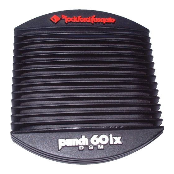
Summary of Contents for Rockford Fosgate Punch 40I
- Page 1 DSM A HANNEL MPLIFIERS PUNCH 40I PUNCH 60IX UNCH UNCH PUNCH 100IX PUNCH 200IX UNCH UNCH ’ WNER A N U A L...
-
Page 2: Practice Safe Sound
Technical Training Institute (RTTI). Please read your warranty and retain your receipt and original carton for possible future use. To add the finishing touch to your new Rockford Fosgate image order your Rockford accessories, which include everything from T- shirts and jackets to hats and sunglasses. -
Page 3: Table Of Contents
ABLE OF ONTENTS Specifications ..................Punch Accessory Pack . -
Page 4: Specifications
- l-... - Page 5 - 2 -...
-
Page 6: Punch Accessory Pack
UNCH CCESSORY 12’ (365.76cm) 12’ (365.76cm) 17’ (518.16cm) 17’ (518.16cm) Blue Remote Red Power Wire Turn-on Wire 1.5’ (45.72cm) 1.5’ (45.72cm) Black Grounding Wire Remote Turn-on Wire Power Ring Power Ring Remote Turn-on Wire Connector Plug Terminals Hex Head and Hex Head and Mounting Screws Power Fuse Holder... -
Page 7: Introduction
NTRODUCTION This manual provides information on the features, installation and operation of the Punch 40i DSM, 60ix DSM, 1 00ix DSM and 200ix DSM amplifiers. We suggest you save this manual for future refer- ence. We strongly recommend you have your Authorized Rockford Fosgate Dealer and Service Center install the new amplifier. - Page 9 The LED, located near the REM terminal, gives a visual indication of the status of the amplifier, lighting when the unit is turned on. *Rockford Fosgate’s Perfect Interface line of accessories includes high quality power and speaker wire, gold plated RCA interconnecting cable and other products to complete your installation.
-
Page 10: Installation Considerations
NSTALLATION ONSIDERATIONS This section focuses on some of the vehicle considerations for installing your new Punch Amplifier. Checking your battery and present sound system, as well as pre-planning your system layout and best wiring routes will save installation time. When deciding how to lay out your new system, be sure that each component will be easily accessible making... -
Page 11: Tools Needed
OOLS EEDED The following is a list of tools you will need for installing the Punch amplifier: Allen Wrenches (7/64” & 3/32”) Voltmeter Wire Strippers Battery Post Wrench Electric Hand Drill w/assorted bits Wire Crimpers (i.e., Perfect Interface RT-KT1) RT-KT1) ATTERY AND HARGING Punch amplifiers will naturally put an extra load on your battery and... -
Page 12: Wiring The System
Leave the wires long at this point to adjust for a precise fit later. 2 . Punch 40i, 60ix, 100ix Prepare the fuseholder supplied with the amplifier. For the Punch... - Page 13 Prepare the power cable for attachment to the amplifier by cable stripping 5/8”of insulation from the end. The use of 8 gauge can interfere with the installation of the end bells. Proper wire dress can prevent this from occurring. To stop the wire from fraying strip the insulation at a 45”...
-
Page 14: Mono Bridging
(-) terminal is the “hot” terminal for the right speaker. DO NOT chassis ground any of the speaker leads as unstable operation may result. When wiring speakers to the amplifiers, we recommend using fuses for speaker protection. (See your Authorized Rockford Fosgate Dealer for more information.) SING THE NTERNAL... -
Page 18: Troubleshooting
If the amp plays, check for shorts or blown voice coiIs in the vehicle’s speaker system. If you are still having problems, have the amplifier checked out by an Rockford Fosgate Dealer. Authorized - 15-... - Page 19 Problem Amplifier gets too hot. Solution 1. Be sure the amplifier is properly mounted. You should be able to place your hand a few inches above the amplifier housing and feel the heat rising when the unit is on. 2. Be sure the amplifie ris properly vented. An ideal situation is to have the air flow through the heatsink fins.
- Page 20 If the noise disappears, install the radio, using only one (1) grounding point. Isolate the radio chassis from the grounding on the dash, and use an antenna grounding loop isolator on the antenna. If noise persists, see your Authorized Rockford Fosgate Dealer. -17-...
-
Page 21: Dynamic Power Measurements
Real World operation of an amplifier. Many manufac- turers, including Rockford Fosgate, at times will measure amplifier power into a fixed resistor (4 Ohm, 2 Ohm). While this method is useful in some types of evaluation and testing, it is not representative of an amplifier that is connected to a speaker and playing music. - Page 22 Information Cubed The data acquired in the testing procedure is then graphed in the form PowerCube. of a 3-dimensional cube. Hence the name Angle The Phase is expressed on the horizontal axis, the Output Voltage Impedance is presented on the vertical axis and the Output Power, displayed on the Z axis.
-
Page 23: Warranty Information
Rockford Fosgate’s discretion. Repaired or replaced electronics will be covered by the balance of the original warranty period only. Rockford Fosgate shall not be responsible for any incidental or consequential damages resulting from a defect in electronics. Some states do not allow the exclusion or limitation of incidental or consequential damages, so the previous limitation may not be applicable. - Page 24 Rockford Fosgate A Division of Rockford Corporation 546 South Rockford D r i v e Tempe, Arizona 85281 U.S.A. In U.S.A., (602) 967-3565 In Canada, call Korbon (905) 567-l 929 In Europe, Fax (49) 4207-801250 REV. C 1/94 01/94 MAN-0679-C...


Need help?
Do you have a question about the Punch 40I and is the answer not in the manual?
Questions and answers