Table of Contents
Advertisement
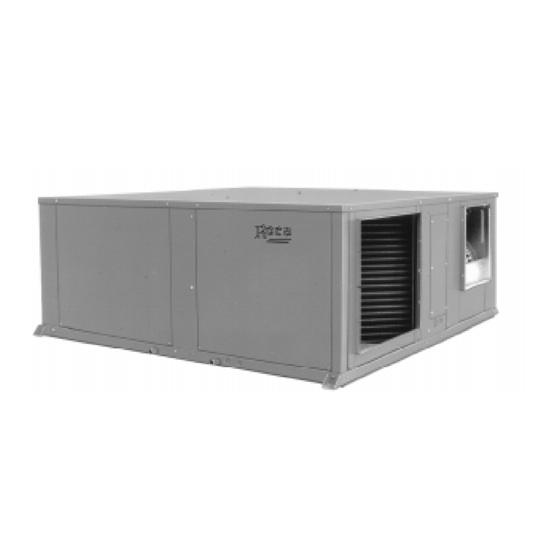
Model BCH
horizontal packaged
air to air heat pump
Technical information
RETURN TO GENERAL INDEX
ER-028/1/91
CGM-97/013
E U R O V E N T
CERTIFIED PERFORMANCE
Clima Roca York S.L. is participating in the EUROVENT Certification Programme.
Products are as listed in the EUROVENT Directory of Certified Products,
in the program
AC 1, AC2
AC3 .
and
Ref.: N-26844 0700
1
Advertisement
Table of Contents

Related Manuals for Roca BCH-7

Summary of Contents for Roca BCH-7
-
Page 1: Technical Information
Technical information RETURN TO GENERAL INDEX E U R O V E N T CERTIFIED PERFORMANCE Clima Roca York S.L. is participating in the EUROVENT Certification Programme. Products are as listed in the EUROVENT Directory of Certified Products, ER-028/1/91 CGM-97/013 AC 1, AC2 AC3 . -
Page 3: Table Of Contents
Index Page Page - Other General - General description Operation - Nomenclature - Control - Summer cycle - Winter cycle - Detail module internal connections Technical specifications with exits to the connector - Function of the pins - Mechanical specifications - Actions according to state of the probe - Physical data - Module... -
Page 5: General
General Balance point Since the heat pump operates by extracting heat from the General description outdoor air, it is possible that sometimes this temperature is The model BCH heat pump is an air to air type of equipment so low that the extracted heat is insufficient to satisfy the that provides air conditioning in summer and in winter by heating demand. -
Page 6: Physical Data
Of the air exposed wires type that allow a rapid heat dissipa- Centrifugal type with direct drive motor. tion, avoiding the thermal inertia that could affect com- These fans develop sufficient pressure for the installation of ponents. Physical data Model BCH-7 BCH-10 BCH-12 BCH-15 BCH-20 BCH-25 BCH-30... -
Page 7: Nominal Features
Nominal features Summer Winter Unit Cooling capacity W Consumption W Heating capacity W Consumption W BCH-7 6 400 3 800 7 100 3 700 BCH-10 9 200 5 000 10 800 4 000 BCH-12 11 600 6 700 12 700... -
Page 8: Sensitive Cooling Capacities
4 300 5 400 6 500 7 200 1.92 8 200 2 200 3 300 4 500 5 600 2.51 BCH-7 19.5 7 500 3 200 4 300 5 400 6 500 2.38 6 800 4 100 5 200 6 300 6 800 2.22... -
Page 9: Sensitive Cooling Capacities
Sensitive cooling capacities Sensitive capacity (W) Compressor Outside Air intake Total power Dry temperature of air °C (DB) air dry humid capacity Model absorbed temperature temperature °C (WB) °C (DB) 19 400 8 300 11 700 15 200 4.70 19.5 17 800 7 700 11 100... -
Page 10: Outdoor Fan Performance
Outdoor fan performance Indoor fan performance Static pressure Power Static pressure Air flow Air flow Power available absorbed available Model Model absorbed mm WG mm WG 1 700 78.4 0.47 58.8 2 000 0.56 1 900 58.8 0.52 39.2 2 200 0.61 2 100 BCH -7... -
Page 11: Installation Instructions
Installation instructions General The BCH heat pumps are delivered as factory charged and tested packaged units. Designed to be installed with ducts, on terraces, rooftops, in lofts or basements. Attention: Fan in operation. Protection of the environment Packing Packing is made of recyclable material. The disposal of same should be carried out in accordance with the regulations on selective residue disposal established by the local authori- ties. -
Page 12: Attaching Unit
Attention: It is essential to use all fixing points on the unit. When the heat pump operates under outdoor temperatures The BCH-7, 10, 12, 15 and 20 have 4 fixing points. below 5°C, the drain tube could become obstructed by ice The BCH-25 and 30 have 6 fixing points. -
Page 13: Air Intake And Discharge Orientations
Starting from the standard unit the orientations of the air intake and discharge of the condenser and evaporator fans can be changed to obtain any of the combinations shown in BCH-7,10,12,15 & 20 the figure below. BCH-7,10,12,15 & 20 This variation of the air intake can be used only in those... -
Page 14: Bch -7
Start-up procedure Electrical installation a) Connect the power supply cable and earth to the In every case the established national regulations should corresponding boards on the controls box. be applied. b) Give power to the auxiliary control line at 220/240.1.50. Each heat pump is delivered with a control box, to which the c) Connect the room thermostat line to 24 V on the boards power supply will be connected across a fused main discon-... -
Page 15: Utilization Limits
Utilization limits Indoor coil inlet air Outdoor coil inlet air Voltage limits temperature temperature DB Operating cycle Operating cycle Nom. 230 V Nom. 400 V Minimum °C Maximum °C Minimum °C Maximum °C Minimum Maximum Minimum Maximum Cool Heat Cool Heat Cool WB Heat DB... -
Page 16: Other
Delayed switch-off of interior fan Function of the pins The interior fan will continue to function for one minute after the stop order. This is to permit dissipation of the energy accumulated in the interior interchanger and represents an energy saving. Optionally, at the jobsite, this option can be deactivated, INTERIOR FAN FUNCTION JP19... -
Page 17: Module
Module SERIAL ROCA CODE NUMBER VALIDITY PLATE COMMUNICATION CONNECTOR BY COMPUTER 006791024 INPUT Y BCH/BCV-97/A EXTERIOR OUTDOOR INPUT G DESCARGA DISCHARGE CONTROL INPUT W BCH/AVO CABLE CONNECTOR INPUT O DESHIELO DEFROST LIQUIDO LIQUID TEST RESET FILTERS STANDBY FILTERS RESET LEDS BUTTONS STANDBY.- INDICATES COMPRESSOR DELAY... -
Page 18: Operating Sequences
Operating sequences corresponding signal from the ambient thermostat to satisfy the cooling demand. See relevant electrical diagrams. 6) When the unit stops at the end of an operating cycle, or Summer cycle: Thermostat in COOL position through a power failure, the logic module will not allow it 1) The 4-way valve is activated through the thermostat. - Page 19 Winter cycle: Thermostat in HEAT position operating voltages to even up. 1) The 4-way valve is deactivated, allowing the position for 7) If the discharge pressure exceeds 28 kg/cm , or the the heating circuit, which means that the indoor coil acts discharge pressure is over 130°C, the logic module will as condenser and the outdoor one as evaporator.
-
Page 20: Operating At -15°C
Defrost cycle (timed) the thermostat's second stage). - It leaves the indoor fan functioning under the first heating The ice which is produced on the outdoor coil during the stage of the thermostat. heating cycle must be eliminated when it begins to block the coil. -
Page 21: Operating Instructions
DSL ambient thermostat for 610 heat pump Operating instructions This thermostat has been designed to proportion a precise General introduction control of the ambient temperature and to give graphic Start up and automatic temperature regulation are imple- information of the mode in which the heat pump is opera- mented by the ambient thermostat. - Page 22 operational modes appear on the liquid crystal display panel: After a few minutes have passed the cooling system will start up, and the cooling symbol, visible on the display, will - Controls the system in the cooling mode. start to flash. (The word is displayed on the panel for 5 seconds).
- Page 23 temperature, this is the minimum differential allowed by e) Off the thermostat. Press the MODE button repeatedly until Repeatedly press the MODE button until the word the heating symbol and cooling symbol are displayed appears on the display. The heat pump will stop and on on the panel (at the same time the word will be the thermostat display panel the word...
-
Page 24: Graphic Information
operational modes). should be cleaned as frequently as necessary with a brush vacuum cleaner or detergent. When installing the thermostat the symbol will be displayed, indicating that the temperature selected is set for the day. By pressing the DAY/NIGHT button the symbol is displayed CAUTION on the panel, indicating that the temperature selected will be... -
Page 25: Bch-7
General dimensions mm BCH-7, 10 MINIMUM MINIMUM CLEARANCE CLEARANCE 22 O.D. DRAIN CONNECTIONS OUTDOOR SIDE VIEW INDOOR SIDE VIEW ELECTRICAL CONNECTIONS DETAIL "Z" OPTIONAL OUTDOOR OPTIONAL INDOOR AIR INTAKE AIR OUTLET OUTDOOR D.12 (4) INDOOR AIR INTAKE AIR OUTLET INDOOR AIR... -
Page 26: Bch-12 & 15
General dimensions mm BCH- 12, 15 & 20 MINIMUM MINIMUM CLEARANCE CLEARANCE 22 O.D. DRAIN CONNECTIONS INDOOR SIDE VIEW OUTDOOR SIDE VIEW ELECTRICAL CONNECTIONS DETAIL "Z" OPTIONAL OUTDOOR OPTIONAL INDOOR AIR INTAKE AIR OUTLET D.12 (4) OUTDOOR INDOOR AIR AIR INTAKE OUTLET OUTDOOR AIR OUTLET... -
Page 27: General Dimensions
General dimensions mm BCH - 25 & 30 MINIMUM MINIMUM CLEARANCE CLEARANCE ELECTRICAL CONNECTIONS INDOOR SIDE VIEW AIR FILTER OUTDOOR SIDE VIEW DETAIL "Z" OPTIONAL INDOOR OPTIONAL OUTDOOR AIR OUTLET AIR INTAKE INDOOR INDOOR AIR INTAKE AIR OUTLET 22 DIAM. D.12 (6) OUTDOOR DRAINAGE... -
Page 28: Wiring Diagrams
Wiring diagram BCH - 7, 230.1.50 230V, 1 ~, 50 Hz, 30 m A CROSS 32 A SECTION 4 mm 006791024 BCH/BCV-97/A INPUT Y EXTERIOR OUT DOOR INPUT G DESCARGA DISCHARGE INPUT W BCH/AVO INPUT O DESHIELO DEFROST LIQUIDO LIQUID TEST RESET FILTERS STANDBY FILTERS... -
Page 29: Wiring Diagrams
Wiring diagram BCH - 10, 12, 15, 230.3.50 BCH - 10, 12, 15, 400.3.50 230V, 3 ~, 50 Hz, 400V, 3 ~, 50 Hz,N, L1 L2 L3 N 400.3.50 230.3.50 30 m A SECTION B SECTION B Q2 (A) Q2 (A) MODEL BCH-10 CROSS... -
Page 30: Wiring Diagram
Wiring diagram BCH - 20, 230.3.50 BCH - 20, 400.3.50 230V, 3 ~, 50 Hz, 400V, 3 ~, 50 Hz,N, 400.3.50 230.3.50 L1 L2 L3 SECTION B SECTION B MODEL Q2 (A) Q2 (A) 30 m A BCH-20 CROSS SECTION B mm 006791024 INPUT Y BCH/BCV-97/A... - Page 31 Wiring diagram BCH - 25 & 30, 230.3.50 BCH - 25 & 30, 400.3.50 230V, 3 ~, 50 Hz, 400V, 3 ~, 50 Hz,N, 400.3.50 230.3.50 L1 L2 L3 SECTION B SECTION B MODEL Q2 (A) Q2 (A) 30 m A BCH-25 BCH-30 CROSS...
- Page 32 Power diagram BCH - 7, 230.1.50...
- Page 33 Power diagram BCH - 10, 12, 15, 230.3.50...
- Page 34 Power diagram BCH - 10, 12, 15, 400.3.50...
- Page 35 Power diagram BCH - 20, 230.3.50...
- Page 36 Power diagram BCH - 20, 400.3.50...
- Page 37 Power diagram BCH - 25 & 30, 230.3.50...
- Page 38 Power diagram BCH - 25 & 30, 400.3.50...
- Page 39 Control diagram BCH - 7, 10, 12, 15, 230.3.50, 400.3.50 230V.1.50 Hz...
- Page 40 Control diagram BCH - 20, 230.3.50, 400.3.50 230V.1.50 Hz...
- Page 41 Control diagram BCH - 25 & 30, 230.3.50, 400.3.50 230V.1.50 Hz...
-
Page 42: Optional Accessories
Filter rack with filter for for BCH-7, 10, 12, 15 & 20 BCH-7, 10, 12, 15 & 20 Air filter for BCH-7, 10, 12, 15 & 20, Duct electric heater RC -220 (the 25 and 30 units are supplied with a for BCH-7, 10, 12, 15, 20, 25 &... -
Page 43: Filter Rack With Filter
Filter rack with filter Due to the shape of the filter rack the access cover to the filter can be placed on any of the four sides of the rack or duct. Designed for installation in the air intakes of either the indoor When designing the air ducts consideration should be given or outdoor fans (only for the indoor one in the case of BCH- to the fact that the use of this accessory, always implies a... -
Page 44: Air Filter
Air filter Can be adapted to either the evaporator or condenser side. Once attached the filter will exceed the conditoner's outer Of the cleanable type, with open cell polyurethane foam filter dimensions by 100 mm. mat. General dimensions mm Note: With the BCH-20 unit this accessory can be connected only in the indoor air return. -
Page 45: Indoor Electric Heaters Rh
General dimensions mm Characteristics Model RH - 5.1 RH - 5.3 RH - 103 RH - 15.3 For installation in heat pump size BCH-7 BCH-7,10 BCH-7,10,12,15,20 BCH-10,12,15,20 Power Power supply V.ph.Hz 230.1.50 230.3.50 or 400.3.50 Consumption 13/7.5... -
Page 46: Duct Electric Heaters Rc-220
Duct electric heaters RC-220 Attention: A flow rate control should be installed together with every For installation in the indoor fan outlet. electric heater, to prevent the heater from operating if the fan Its intended function is to operate as an emergency heater. has not been switched on. - Page 48 Clima Roca York, S.L. AIR CONDITIONING HEATING Paseo Espronceda, 278 TILES 08204 Sabadell (Barcelona) - Spain Telephone (34) 937 102 700 BATHROOMS Telefax (34) 937 117 285...
Need help?
Do you have a question about the BCH-7 and is the answer not in the manual?
Questions and answers