Table of Contents
Advertisement
MediaCento
Extend audio and video signals via an existing LAN.
Distribute HDMI video to an unlimited number of displays using IP
multicast, or make eye-catching video walls of up to 8 x 8 displays.
Contact
Order toll-free or for FREE 24/7 technical support in the U.S.:
Information
Call 877-877-BBOX (outside U.S. call 724-746-5500)
www.blackbox.com • info@blackbox.com
IPX with PoE
™
VX-HDMI-POE-MTX
VX-HDMI-POE-MRX
Advertisement
Table of Contents

Related Manuals for Black Box VX-HDMI-POE-MTX


Summary of Contents for Black Box VX-HDMI-POE-MTX
- Page 1 VX-HDMI-POE-MTX VX-HDMI-POE-MRX MediaCento IPX with PoE ™ Extend audio and video signals via an existing LAN. Distribute HDMI video to an unlimited number of displays using IP multicast, or make eye-catching video walls of up to 8 x 8 displays.
- Page 2 Trademarks Used in this Manual Trademarks Used in this Manual Black Box and the Double Diamond logo are registered trademarks, and MediaCento is a trademark, of BB Technologies, Inc. Bonjour and Apple are registered trademarks of Apple, Inc. Windows is a registered trademark of Microsoft Corporation.
-
Page 3: Instrucciones De Seguridad
FCC and IC RFI Statement/NOM Statement FEDERAL COMMUNICATIONS COMMISSION AND INDUSTRY CANADA RADIO FREQUENCY INTERFERENCE STATEMENTS This equipment generates, uses, and can radiate radio-frequency energy, and if not installed and used properly, that is, in strict accordance with the manufacturer’s instructions, may cause inter ference to radio communication. - Page 4 NOM Statement 4. Todas las instrucciones de operación y uso deben ser seguidas. 5. El aparato eléctrico no deberá ser usado cerca del agua—por ejemplo, cerca de la tina de baño, lavabo, sótano mojado o cerca de una alberca, etc. 6.
- Page 5 NOM Statement 16. El cable de corriente deberá ser desconectado del cuando el equipo no sea usado por un largo periodo de tiempo. 17. Cuidado debe ser tomado de tal manera que objectos liquidos no sean derramados sobre la cubierta u orificios de ventilación. 18.
-
Page 6: Table Of Contents
Table of Contents Table of Contents Specifications ....................8 Overview ....................10 2.1 Introduction ..................10 2.2 Features ....................10 2.3 What’s Included ................... 11 2.4 Additional Items You Will Need ............11 2.5 Hardware Description ................12 2.5.1 Transmitter ................12 2.5.2 Receiver ................... - Page 7 Table of Contents Troubleshooting .................... 42 8.1 Problems/Solutions ................42 8.2 Contacting Black Box ................43 8.3 Shipping and Packaging ...............43 Appendix: Connector Pinouts ................44 877-877-BBOX (2269) | BlackBox.com Page 7...
-
Page 8: Specifications
Chapter 1: Specifications 1. Specifications Technical Specifications Approvals FCC, TUV, CE, UL , CSA, RoHS, WEEE ® Bandwidth 120 Mbps maximum Default IP Address 169.254.x.x (with no DHCP address) NOTE: To find the IP address of any receiver, simply connect to monitor and power up to get IP address. - Page 9 Chapter 1: Specifications Technical Specifications (continued) Connectors (1) HDMI female, (1) RJ-45 interconnect/LAN connection, (1) 2.1-mm barrel connector for power, (2) RJ-12 6P6C† †NOTE: Only 4 center pins are used at this time. Indicators (1) LED for Link and Power; (1) LED for Network Activity Environmental Temperature Tolerance:...
-
Page 10: Overview
Chapter 2: Overview 2. Overview 2.1 Introduction The MediaCento IPX with PoE is a perfect solution for audio and video signal extension via an existing Local Area Network (LAN) system. With multicast technology, one local unit can drive multiple remote units with no extra network load. -
Page 11: What's Included
Chapter 2: Overview 2.3 What’s Included • MediaCento IPX Multicast Transmitter (VX-HDMI-POE-MTX) or MediaCento IPX Multicast Receiver (VX-HDMI-POE-MRX) • (1) U.S. power supply • (1) U.S. power cord • (4) foot pads • This user manual VX-HDMI-POE-MTX also has: • (1) MediaCento IPX Multicast Transmitter •... -
Page 12: Hardware Description
Chapter 2: Overview 2.5 Hardware Description 2.5.1 Transmitter Figure 2-1. Transmitter front panel. Figure 2-2. Transmitter back panel. Figure 2-3. Transmitter top panel. 877-877-BBOX (2269) | BlackBox.com Page 12... - Page 13 Chapter 2: Overview Table 2-1. Components of the Transmitters. Number Component Description F2 button See Section 2.6.4. F1 button See Section 2.6.4. Set up an identical position for Rotary switch all units RJ-12 connector Serial port 1: For system control RJ-12 connector Serial port 2: For data transfer Locking barrel connector for...
-
Page 14: Receiver
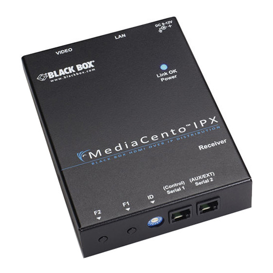
Chapter 2: Overview 2.5.2 Receiver Figure 2-4. Receiver front panel. Figure 2-5. Receiver back panel. Figure 2-6. Receiver top panel. 877-877-BBOX (2269) | BlackBox.com Page 14... - Page 15 Chapter 2: Overview Table 2-2. Components of the Receivers. Number Component Description F2 button See Section 2.6.4. F1 button See Section 2.6.4. Set up an identical position for all Rotary switch units RJ-12 connector Serial port 1: For system control RJ-12 connector Serial port 2: For data transfer Locking barrel connector for...
-
Page 16: Indicators
Chapter 2: Overview 2.5.3 Indicators The LEDs on the extender units show the real-time status indicating the linking and communication between the Transmitter/Sender unit and the Receiver unit. Users can identify the current status through the LED indicators on the unit. NOTE: The system will disable the video output signal when it detects non-HDCP- compliant display(s) trying to play on the HDCP video source. -
Page 17: Edid Copy
Chapter 2: Overview Table 2-3. Function buttons (continued). Button Action Description 1. Press and hold the F1 button. 2. Apply power to the unit. Resets the box to factory 3. Release right after the defaults. Network Status LED starts blinking. 4. -
Page 18: Installation
Chapter 3: Installation 3. Installation WARNINGS: Make sure that all devices are powered off before connecting to the unit. Make sure all devices you will connect are properly grounded. Place cables away from fluorescent lights, air conditioners, and machines. Allow adequate space around the unit for air circulation. System Requirements for PoE 1. - Page 19 Chapter 3: Installation VX-HDMI-POE-RX HDMI display PC source PoE Ethernet Switch with IGMP VX-HDMI-POE-TX (LPB2910A) Figure 3-1. Connection pattern for unicast configuration with an Ethernet switch. Monitor player PoE Ethernet switch with IGMP Monitor Monitor Blu-ray (LPB2926A) Monitor Monitor Figure 3-2. Multicast configuration. 877-877-BBOX (2269) | BlackBox.com Page 19...
- Page 20 Chapter 3: Installation MediaCento IPX POE MediaCento IPX POE ™ ™ Transmitter Receivers Digital displays (VX-HDMI-POE-TX) (VX-HDMI-POE-RX) Diagram HDMI cables Rule Size Layer 3 switch HDMI cable with IGMP CATx cable CATx cables PoE Ethernet switch with IGMP (LPB2926A) Figure 3-3. Video Wall configuration. 877-877-BBOX (2269) | BlackBox.com Page 20...
-
Page 21: Configuration
Chapter 4: Configuration 4. Configuration 4.1 Connecting to the Devices You can access devices through the Web GUI, serial interface, or Telnet for advanced configuration of network and video settings. See Chapter 6 for telnet and serial connection. 4.2 Connect to Web GUI Using the IP Address To see the IP address of a receiver: Connect receiver and transmitter to a network switch or directly with a cable. -
Page 22: Connect To Web Gui Using The Host Name
Chapter 4: Configuration 4.3 Connect to Web GUI Using the Host name Bonjour is needed to access the Web interface by the hostname. Apple products ® ® usually have this installed. If needed, you can download the free version from apple.com. - Page 23 Chapter 4: Configuration Table 4-1. Channel listing for unicast address. Rotary Switch Four Digits Domain Name 0000 http://ast-gateway0000.local 1000 http://ast-gateway1000.local 0100 http://ast-gateway0100.local 1100 http://ast-gateway1100.local 0010 http://ast-gateway0010.local 1010 http://ast-gateway1010.local 0110 http://ast-gateway0110.local 1110 http://ast-gateway1110.local 0001 http://ast-gateway0001.local 1001 http://ast-gateway1001.local 0101 http://ast-gateway0101.local 1101 http://ast-gateway1101.local 0011 http://ast-gateway0011.local 1011...
-
Page 24: Network Information For Transmitter And Receiver
Chapter 4: Configuration 4.4 Network Information for Transmitter and Receiver • IP Mode – Auto IP, DHCP, Static - Auto IP (default) – Uses Zero Conf to find an open IP address in the 169.254.x.x range. - DHCP – Assign an IP address through DHCP. - Static –... -
Page 25: Transmitter
Chapter 4: Configuration 4.4.1 Transmitter Video over IP: Figure 4-3. Video over IP screen for transmitter. 1. Click on the Functions tab. 2. Check the box next to Enable Video over IP. 3. Check the box next to Enable Video Wall. 877-877-BBOX (2269) | BlackBox.com Page 25... - Page 26 Chapter 4: Configuration Serial over IP: Figure 4-4. Serial over IP for transmitter. 1. Check the box next to Enable Serial over IP. 2. Select the Operation Mode from the four radio buttons: • Type 1 (Need extra control instructions. For advanced usage.) •...
-
Page 27: Receiver
Chapter 4: Configuration 4.4.2 Receiver Video Over IP: Figure 4-5. Video over IP for receiver. 1. Click on the Functions tab. 2. Check the box next to Enable Video over IP. 3. Check the box next to Enable Video Wall. 4. - Page 28 Chapter 4: Configuration Serial over IP: Figure 4-6. Serial over IP for receiver. 1. Check the box next to Enable Serial over IP. 2. Select the Operation Mode from the four radio buttons: • Type 1 (Need extra control instructions. For advanced usage.) •...
-
Page 29: Video Wall
Chapter 5: Video Wall 5. Video Wall 5.1 Application Diagram Using the Video Wall features, you can send video and audio to unlimited ouputs through IP. Format the video wall so that separate sections of the video can be sent to different outputs. -
Page 30: Video Wall Setup
Chapter 5: Video Wall 5.2 Video Wall Setup Step 1: Use the show OSD button to display the IP/Name of your receiver units. Select “All” from the Apply To drop down box and check the Show OSD check box. Click Apply to display the OSD on the displays connected to receivers. This information will be used in determining position of each receiver in the video wall. -
Page 31: Bezel Compensation
Chapter 5: Video Wall 5.3 Bezel Compensation Measurements of the display will need to be taken to set up bezel compensation. Measuring units (inch, cm, mm) do not matter, but the same unit should be used for all measurements. Figure 5-3. Wall size and position layout screen. Step 1: Measure the outer dimensions of the display (edge to edge including bezel). -
Page 32: Accessing Through Serial Or Telnet
Chapter 6: Accessing through Serial or Telnet 6. Accessing through Serial or Telnet 6.1 Accessing through Serial 1. Using the client, select “serial” and enter “115200” for the speed (baud rate). Figure 6-1. PuTTY configuration screen using serial. 2. No username or password is required. Just press enter. 877-877-BBOX (2269) | BlackBox.com Page 32... -
Page 33: Accessing Through Telnet
Chapter 6: Accessing through Serial or Telnet 6.2 Accessing through Telnet 1. Using the client, enter in the IP address of the device. 2. Change the port to 24. Figure 6-2. PuTTY configuration screen using Telnet. 3. The default password is root. 877-877-BBOX (2269) | BlackBox.com Page 33... -
Page 34: Command-Line Interface
Chapter 7: Command-Line Interface 7. Command-Line Interface (CLI) These are advanced configurations and require knowledge of IP networking protocols and multicasting. Do not attempt to run any commands, modify files, or change any other settings apart from the specific configurations noted here. All commands are case-sensitive. -
Page 35: Advanced Ip Commands
Chapter 7: Command-Line Interface Figure 7-2. Current configured parameters list. To reset to factory default, setting the IP mode to autoip and removing any overrides, type in: reset_to_default.sh To change the baud rate of the serial extension interface, type in: stty X –F /dev/ttyS0 (replace X with desired baud rate) To disable/enable the link for a specific device, type in:... -
Page 36: Advanced Multicast Ip Configuration
Chapter 7: Command-Line Interface 2. DHCP client gets an address from the local DHCP server. CAUTION: Make sure a DHCP client is connected or problems will occur. 3. Static allows you to manually change the IP address and netmask of the device. This requires further input before reboot. -
Page 37: Receiver
Chapter 7: Command-Line Interface To change the hostname ID of the transmitter, type in: astparam s hostname_id B0B1B2B3 ast_send_event -1 e_chg_hostname To override DIP rotary switch setting on bootup: astparam s reset_ch_on_boot n (space between boot and the n) astparam save reboot 7.2.2 Receiver To change the multicast group IP, type in:... - Page 38 Chapter 7: Command-Line Interface Table 7-1. Channel listing for multicast address. Channel IDs Multicast Address 225.0.100.0 225.0.100.1 225.0.100.8 225.0.100.9 225.0.100.100 225.0.100.101 225.0.100.110 225.0.100.111 225.0.101.0 225.0.101.1 225.0.101.8 225.0.101.9 225.0.101.100 225.0.101.101 225.0.101.110 225.0.101.111 877-877-BBOX (2269) | BlackBox.com Page 38...
-
Page 39: Serial Extension
Chapter 7: Command-Line Interface 7.3 Serial Extension Serial extension can be done from one transmitter to all linked receivers. Telnet serial extension is also available as a replacement of serial. Serial extension information: Default baud rate: 9600 (unless changed manually) Data bits: 8 Parity: Even Stop bits: 1... -
Page 40: Telnet Extension
This disables serial input coming from a transmitter but allows for 2-way communication to specific devices. NOTE: Telnet extension needs serial extension setting changed to “Type 2 guest mode” in the Web interface. For details, contact Black Box Technical Support at 724-746-5500 or info@blackbox.com. To set up a Telnet extension: 1. - Page 41 Chapter 7: Command-Line Interface 2. Turn off line echo and local line editing. Figure 7-6. Turning off line echo and local line editing. 877-877-BBOX (2269) | BlackBox.com Page 41...
-
Page 42: Troubleshooting
Chapter 8: Troubleshooting 8. Troubleshooting 8.1 Problem/Solutions Problem: No video on monitor at bootup. Solutions: 1. Check the device power using the Link/Power LED. 2. Check the network connection using the Network LED. 3. Check the video connection using the Link/Power LED. 4. -
Page 43: Contacting Black Box
• Package it carefully. We recommend that you use the original container. • If you are returning the unit, make sure you include everything you received with it. Before you ship for return or repair, contact Black Box to get a Return Authorization (RA) number. -
Page 44: Appendix: Connector Pinouts
Appendix: Connector Pinouts Appendix. Connector Pinouts Figure A-1 shows the DB9 to RJ-12 or RJ-11 connector pinouts. Figure A-1. DB9 to RJ-12 6P6C or RJ-11 (4P4C) cable pinout. 877-877-BBOX (2269) | BlackBox.com Page 44... - Page 45 NOTES 877-877-BBOX (2269) | BlackBox.com Page 45...
- Page 46 NOTES 877-877-BBOX (2269) | BlackBox.com Page 46...
- Page 47 NOTES 877-877-BBOX (2269) | BlackBox.com Page 47...
- Page 48 877-877-2269 or BlackBox.com. About Black Box Black Box provides an extensive range of networking and infrastructure products. You’ll find everything from cabinets and racks and power and surge protection products to media converters and Ethernet switches all supported by free, live 24/7 Tech Support available in 60 seconds or less.
Need help?
Do you have a question about the VX-HDMI-POE-MTX and is the answer not in the manual?
Questions and answers