Table of Contents
Advertisement
Advertisement
Table of Contents

Related Manuals for Tangent Medix KW

Summary of Contents for Tangent Medix KW
- Page 1 ...
- Page 2 Copyright 2012 All Rights Reserved Manual Version 1.2 The information contained in this document is subject to change without notice. We make no warranty of any kind with regard to this material, including, but not limited to, the implied warranties of merchantability and fitness for a particular purpose. We shall not be liable for errors contained herein or for incidental or consequential damages in connection with the furnishing, performance, or use of this material. This document contains proprietary information that is protected by copyright. All rights are reserved. No part of this document may be photocopied, reproduced or translated to another language without the prior written consent of the manufacturer. TRADEMARK ®, ® ® Intel Pentium and MMX are registered trademarks of Intel Corporation. ® ® Microsoft and Windows are registered trademarks of Microsoft Corporation. Other trademarks mentioned herein are the property of their respective owners. Safety IMPORTANT SAFETY INSTRUCTIONS 1. To disconnect the machine from the electrical power supply, turn off the power switch and remove the ...
- Page 3 CE MARK This device complies with the requirements of the EEC directive 2004/108/EC with regard to “Electromagnetic compatibility” and 2006/95/EC “Low Voltage Directive”. This device complies with part 15 of the FCC rules. Operation is subject to the following two conditions: (1) This device may not cause harmful interference. (2) This device must accept any interference received, including interference that may cause undesired operation. ...
- Page 4 LEGISLATION AND WEEE SYMBOL 2002/96/EC Waste Electrical and Electronic Equipment Directive on the treatment, collection, recycling and disposal of electric and electronic devices and their components. The crossed dust bin symbol on the device means that it should not be disposed of with other household wastes at the end of its working life. Instead, the device should be taken to the waste collection centers for activation of the treatment, collection, recycling and disposal procedure. To prevent possible harm to the environment or human health from uncontrolled waste disposal, please separate this from other types of wastes and recycle it responsibly to promote the sustainable reuse of material resources. ...
-
Page 5: Table Of Contents
Table of Contents 1. Packing List .........1 1‐1. Standard Items ............1 1‐2. Optional Items ............2 2. System View .......3 2‐1. Front & Side View ............3 2‐2. Rear View ..............3 2‐3. I/O view ..............4 2‐4. Dimensions ..............5 2‐4‐1. 15.6" System ................5 2‐4‐2. 18.5" System ................5 2‐4‐3. 21.5" System ................5 3. System Assembly ......6 3‐1. Open the Chassis Cover ...........6 3‐2. RAM Module Replacement ........7 3‐3. HDD Replacement ...........8 4. Peripheral Installation ....9 4‐1. MSR Installation ............9 4‐2. Cash Drawer Installation ........10 5. Specification .......12 4 ... - Page 6 6. Jumper Setting ......16 6‐1. C48 Motherboard ............16 6‐1‐1. Motherboard Layout ..........16 6‐1‐2. Connectors & Functions ........18 6‐1‐3. Jumper & BIOS/Utility Setting ......19 6‐2. C68 Motherboard ............25 6‐2‐1. Motherboard Layout ..........25 6‐2‐2. Connectors & Functions ........26 6‐2‐3. Jumper Setting .............27 5 ...
- Page 7 The page is intentionally left blank. ...
-
Page 8: Packing List
1.Packing List 1‐1. Standard Items System Power adapter Driver bank Power cord User manual RJ45‐DB9 cable (x2) Allen wrench Note: Power cord will be supplied differently according to region or country. 7 ... -
Page 9: 1-2. Optional Items
1‐2. Optional Items MSR 8 ... -
Page 10: System View
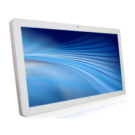
. System View 2‐1. Front & Side View 1. Touch Screen 3. Ventilation 2. Built‐in Web Cam 4. MSR Cable Hole 2‐2. Rear View 5. VESA Mounting Holes 6. Safety Label 7. Cable Cover ... -
Page 11: 2-3. I/O View
2‐3. I/O View Atom Motherboard Item No. Description a DC IN LAN b Cash Drawer c MIC IN d e Line Out f COM Port 1, 2, 3, 4 (from left to right) g USB(x4) Printer h Power Button i VGA j HDD 5V ... - Page 12 Sandy Bridge Motherboard Item No. Description MIC IN a DC IN b LAN (x2) c d Cash Drawer e Line Out f COM Port 1, 2, 3, 4 (from left to right) USB(x4) g Printer h Power Button i j VGA ...
-
Page 13: 2-4 Dimensions
2‐4 Dimensions 2‐4‐1. 15.6" System 2‐4‐2. 18.5" System 2‐4‐3. 21.5" System ... -
Page 14: System Assembly
. System Assembly 3‐1. Open the Chassis Cover The motherboard and RAM module can be replaced by opening the chassis cover, which is located on the back side of the system. Please follow the steps below to open the chassis cover. 1. Turn to the back side of the system and loosen the thumb screws (x2) to release the cable cover first. 2. Loosen the hex socket cap screws (x8) to open the back cover of the system. * Please use an Allen wrench to tighten/loosen the screws. ... -
Page 15: 3-2. Ram Module Replacement
3‐2. RAM Module Replacement To remove and replace the RAM module, please first open the chassis cover per steps described in chapter 3‐1. Removing a RAM module 1. Find the memory slot at the right side of the motherboard. Atom Motherboard Sandy Bridge Motherboard 2. Flip the ejector clips outwards to remove the memory module from the memory slot. Installing a RAM module 3. Slide the memory module into the memory slot and press down until the ejector clips snaps in place. ... -
Page 16: 3-3. Hdd Replacement
3‐3. HDD Replacement To remove and replace the HDD, please first open the cable cover per steps described in chapter 3‐1‐1. 1. Find the HDD located at the right side. 2. Pull the HDD tray from the system. For easier removal pull the plastic sheet (see picture) at the same time. 3. Attach the HDD to the HDD tray and slide it into the slot until it snaps in place. * Please note the top of the HDD should be on the upper side. ... -
Page 17: Peripheral Installation
Peripheral Installation 4‐1. MSR Installation To install MSR, please open the cable cover first per steps described in chapter 3‐1‐1. 1. Insert MSR module in place and fasten the screws (x2) on the back to secure the module. 2. Connect MSR cable to the connector on system side. 3. Close the cable cover and fasten screws (x2). Make sure the MSR cable is threaded through the MSR cable hole on the system. 16 ... -
Page 18: 4-2. Cash Drawer Installation
4‐2. Cash Drawer Installation You can install a cash drawer through the cash drawer port. Please verify the pin assignment before installation. Pin Signal Cash Drawer Pin Assignment GND 2 DOUT bit0 3 DIN bit0 4 12V / 19V 5 DOUT bit1 6 1 6 GND Cash Drawer Controller Register The Cash Drawer Controller use one I/O addresses to control the Cash Drawer. Register Location: 48Ch Attribute: Read / Write Size: 8bit BIT BIT7 BIT6 BIT5 BIT4 BIT3 BIT2 BIT1 ... - Page 19 Bit 7: Reserved Bit 6: Cash Drawer “DIN bit0” pin input status. = 1: the Cash Drawer closed or no Cash Drawer = 0: the Cash Drawer opened Bit 5: Reserved Bit 4: Reserved Bit 3: Cash Drawer “DOUT bit1” pin output control. = 1: Opening the Cash Drawer = 0: Allow close the Cash Drawer Bit 2: Cash Drawer “DOUT bit0” pin output control. = 1: Opening the Cash Drawer = 0: Allow close the Cash Drawer Bit 1: Reserved Bit 0: Reserved Note: Please follow the Cash Drawer control signal design to control the Cash Drawer. Cash Drawer Control Command Example Use Debug.EXE program under DOS or Windows98 Command Cash Drawer O 48C 04 Opening O 48C 00 Allow to close ► Set the I/O address 48Ch bit2 =1 for opening Cash Drawer by “DOUT bit0” pin control. ► Set the I/O address 48Ch bit2 = 0 for allow close Cash Drawer. Command Cash Drawer I 48C ...
-
Page 20: Specification
Specification . Model Name VITA KW Medix KW Mainboard Atom Motherboard CPU Intel Pineview dual core D525 1.8G Chipset Intel ICH8M System Memory 2 x DDR3 SO‐DIMM slot, up to 4GB Graphic Memory Intel GMA 3150 share system memory up to 256MB LCD/Touch Panel LCD Size 15.6" LED LCD 18.5" LED LCD Brightness 250 nits Maximum Resolution 1366 x 768 Touch Screen Type True flat resistive touch / True flat projected capacitive touch Storage HDD 2.5" Slim HDD bay, SATA HDD Peripherals Web Cam (Build‐in) 2M Web Cam WiFi (Optional) 802.11 b/g/n WLAN card MSR‐right side(Optional) 3 Track(USB) Expansion ... - Page 21 Environment EMC & Safety FCC Class A, CE, LVD Operating Temperature 0°C ~ 40°C (32°F ~ 104°F) Storage Temperature ‐20° ~ 60°C (‐4°F ~ 140°F) Operating Humidity 5% ‐ 95% RH non‐condensing Storage Humidity 5% ‐ 95% RH non‐condensing Dust & Water Proof IP 54 (front panel) Dimensions 396 x 245 x 48 mm 464 x 284 x 48 mm (W x D x H) Weight 4.5kg / 5.5kg 6.8kg / 7.8kg (N.W./G.W.) Mounting 75mm x 75mm Standard VESA / Panel Mount OS Support Windows XP Pro, Linux , POS Ready 2009,Windows Vista ,Windows 7 * Product specifications are subject to change without prior notice. ...
- Page 22 Model Name VITA KW Medix KW Mainboard Sandy Bridge Motherboard CPU Intel Sandy Bridge CPU, LGA 1155‐pin, 32nm i5‐2390T 2.7G, L2 6M, 65W i3‐2120 3.3G, L2 3M, 65W Pentium G850 2.9G, L2 3M, 65W Pentium G620T 2.2G, L2 3M, 65W Celeron G540 2.5G, L2 2M, 65W Chipset Intel Q67 PCH (Processor Controller Hub, AMT supported_ highend) System Memory 1 x Long DIMM socket up to 8GB DDR3 1066/1333 Mhz, standard 1GB LCD/Touch Panel LCD Size 15.6" LED LCD 18.5" LED LCD Brightness 250 nits Maximum Resolution 1366 x 768 Touch Screen Type True flat resistive touch / True flat projected capacitive touch Storage HDD 2.5" Slim HDD bay, SATA HDD Peripherals Web Cam (Build‐in) 2M Web Cam MSR‐right side(Optional) 3 Track(USB) WiFi (Optional) ...
- Page 23 Audio Speaker 2 x 2W Power Power Adapter DC 19V / 120W Environment EMC & Safety FCC Class A, CE, LVD Operating Temperature 0°C ~ 40°C (32°F ~ 104°F) Storage Temperature ‐20° ~ 60°C (‐4°F ~ 140°F) Operating Humidity 5% ‐ 95% RH non‐condensing Storage Humidity 5% ‐ 95% RH non‐condensing Dust & Water Proof IP 54 (front panel) Dimensions 396 x 245 x 48 mm 464 x 284 x 48 mm (W x D x H) Weight 4.5kg / 5.5kg 6.8kg / 7.8kg (N.W./G.W.) Mounting 75mm x 75mm Standard VESA / Panel Mount OS Support Windows XP Pro, Linux , POS Ready 2009,Windows Vista, Windows 7 * Product specifications subject to change without prior notice. ...
-
Page 24: Jumper Setting
6. Jumper Setting 6‐1. Atom Motherboard 6‐1‐1. Motherboard Layout 23 ... - Page 25 24 ...
-
Page 26: 6-1-2. Connectors & Functions
6‐1‐2. Connectors & Functions Connector Purpose CN1 Power Button Connector CN3 Printer Port Reset CN4 Printer Port CN5/8 HDD Power CN11 COM5 For Touch CN13 Card Reader Connector CN14 Line out CN15 HDD LED CN16 Speaker & MIC CN18 MIC IN CN20/JP10 System Indicator CN22 USB Port CN23 PS2 KEYBOARD CN26 LVDS CN27 Inverter Connector CN29 System Fan DDR3_A1 DDR3 SO‐DIMM1 DDR3_A2 DDR3 SO‐DIMM2 PRN1 ... -
Page 27: 6-1-3. Jumper & Bios/Utility Setting
6‐1‐3. Jumper & BIOS/Utility Setting COM2 RS232/485/422 Setting Function JP4 ▲RS232 5 7 11 9 12 8 10 10 11 9 5 7 RS485 12 8 10 10 9 9 RS422 12 10 COM3 & COM4 Power Setting COM3 and COM4 can be set to provide power to your serial device. The voltage can be set to +5V or 12V by setting jumper JP18 on the motherboard. When enabled, the power is available on pin 10 of the RJ45 serial connector. If you use the serial RJ45 to DB9 adapter cable, the power is on pin 9 of the DB9 connector. ... - Page 28 4. To switch on the power, select "Power". Please save the change before exiting BIOS so as to go for physical jumper adjustment. COM3/COM4 Jumper setup Function JP18 ▲+5V 8 COM3 +12V 8 +5V 8 COM4 ▲+12V 8 Function JP18 ▲CMOS Normal CMOS Reset ...
- Page 29 Cash Drawer Power Setting Function JP19 +19V ▲+12V Power Mode Setting Function JP9 ▲ATX Power AT Power System Indicator Function JP10 ▲Disable 6 8 Enable 4 Inverter Selection Function JP14 ▲ CCFL 4 LED 6 ...
- Page 30 CMOS Operation Mode CMOS Reset To clear the CMOS, 1. Remove the power cable from the system. 2. Open the system, and set the ‘CMOS Operation jumper’ from ‘CMOS Normal’ to ‘CMOS Reset’. (refer to the jumper shown below) 3. Connect the power cable to the system, and power on the system: in ATX mode: press the power button and it will fail power on in AT mode: turn on system power 4. Remove the power cable from the system. 5. Return the "CMOS Operation mode" jumper setting from "CMOS Reset" to "CMOS normal". 6. Connect the power cable and power on the system. Function JP1 ▲CMOS Normal CMOS Reset ▲ = Manufacturer Default Setting ...
- Page 31 LCD ID Setting Several configurations are applied to different sizes of panel. Please refer to the followings to complete relevant settings. LVDS Output JP8 Resolution Bits Channel Interface 800 x 600 24 Single 6 1024 x 768 24 Single ...
- Page 32 4. To switch on the power, select "+12V". Please save the change before exiting BIOS to avoid data lost. LCD Brightness Control Setting Please note Brightness Control can only be set by setting jumper JP14 for CCFL on the motherboard C48 V2.1. By default, the inverter is CCFL on the motherboard jumper setting. 1. Power on the system, and press the <DEL> key when the system is booting up to enter the BIOS Setup utility. 2. Select the Advanced tab. 3. Select Power Configuration COM/VGA Ports and press <Enter> to go to display the available options. 4. To change the brightness, select “Brightness Control” and press <Enter>. Choose the desired brightness level (0~7) press <Enter>. Save the change by pressing F10. NOTE: the new brightness will take effect after the system has restarted. ...
-
Page 33: 6-2-1. Motherboard Layout
6-2. Sandy Bridge Motherboard 6-2-1. Motherboard Layout 32 ... -
Page 34: Connectors & Functions
6-2-2. Connectors & Functions Connector Purpose CN1/2 SATA power Connector CN3 LVDS Connector CN4 LVDS INVERTER Connector CN5 SATA HDD LED Connector CN6 DVI Connector CN7 BATTERY Connector CN9 FT STATUS INTERFACE CN10/11 USB Port(Internal) CN12 Card Reader Connector(COM6) CN13 RF Connector CN14 COM5 for Touch CN15 SPEAKER & MIC Connector (Internal) CN16 PS2 Keyboard Connector CN17 Power On LED Connector CN18/CN19 LAN1/2 LED(Internal) CN20 Power button(Internal) CN21 Line out JACK DDR3_A1 ... -
Page 35: Jumper Setting
6-2-3. Jumper Setting Power Mode Setting Function JP1 ▲ATX Power AT Power COM2 RS232/485/422 Setting Function JP10 JP13 11 5 7 9 9 ▲RS232 8 10 11 9 9 RS485 8 10 4 6 ... - Page 36 Inverter Selection Function JP3 ▲ CCFL 4 LED 6 ME Update Function JP8 ▲Lock Un‐lock Hardware Reset Function JP9 ▲System Normal System Reset USB Touch Power Setting for CN11 Connector Function JP11 ▲+5VSB 4 ...
- Page 37 CMOS Operation Mode CMOS Reset To clear the CMOS, 1. Remove the power cable from the system. 2. Open the system, and set the ‘CMOS Operation jumper’ from ‘CMOS Normal’ to ‘CMOS Reset’. (refer to the jumper shown below) 3. Connect the power cable to the system, and power on the system: in ATX mode: press the power button and it will fail power on in AT mode: turn on system power 4. Remove the power cable from the system. 5. Return the "CMOS Operation mode" jumper setting from "CMOS Reset" to "CMOS normal". 6. Connect the power cable and power on the system. Function JP7 ▲CMOS Normal CMOS Reset COM3 & COM4 Power Setting COM3 and COM4 can be set to provide power to your serial device. The voltage can be set to +5V or 12V by setting jumper JP18 on the motherboard. When enabled, the power is available on pin 10 of the RJ45 serial connector. If you use the serial RJ45 to DB9 adapter cable, the power is on pin 9 of the DB9 connector. By default, the power option is disabled in the BIOS. BIOS/Utility setup 1. Press <DEL> key to enter BIOS SETUP UTILITY when system boot up. 2. Find tab "Advanced". 3. Select "Power Configuration COM/VGA Ports" and press <Enter> to go to sub screen. ▲ = Manufacturer Default Setting ...
- Page 38 4. To switch on the power, select "Power". Please save the change before exiting BIOS so as to go for physical jumper adjustment. COM3/COM4 Jumper setup Function JP12 ▲+5V 8 6 COM3 +12V 8 6 +5V 8 COM4 ▲+12V 6 ...
- Page 39 LCD ID Setting LVDS Output Panel# Resolution Bits Channel Interface JP2 1 800 x 600 18 LVDS 9 Single Panel 10 9 3 800 x 600 24 Single LVDS 4 10 ...
- Page 40 The page is intentionally left blank. ...
Need help?
Do you have a question about the Medix KW and is the answer not in the manual?
Questions and answers