FujiFilm FINEPIX S9100 Service Manual
Hide thumbs
Also See for FINEPIX S9100:
- Brochure & specs (4 pages) ,
- Quick start (2 pages) ,
- Basic manual (185 pages)
Table of Contents
Advertisement
Quick Links
BECAUSE THIS PRODUCTIS RoHS LEAD-FREE COMPLIANT, USE THE DESIG-
NATED AFTER-SELES PARTS AND THE DESIGNATED LEAD-FREE SOLDER WHEN
PERFORMING REPAIRS. (Refer to page 3 to page 5)
THE COMPONENTS IDENTIFIED WITH THE MARK "
DIAGRAM AND IN THE PARTS LIST ARE CRITICAL FOR SAFETY.
PLEASE REPLACE ONLY WITH THE COMPONENTS SPECIFIED ON THE SCHEMATIC
DIAGRAM AND IN THE PARTS LIST.
IF YOU USE PARTS NOT SPECIFIED, IT MAY RESULT IN A FIRE AND AN
ELECTRICAL SHOCK.
FUJI PHOTO FILM CO., LTD.
CAUTION
WARNING
Confidential: FUJIFILM Service Center Use Only
DIGITAL CAMERA
FinePix S9100/
SERVICE MANUAL
US/EU/EG/EE/AS/CH/JP-Model
" ON THE SCHEMATIC
S9600
Ref.No.:ZM00654-102
Printed in Japan 2007.01
Advertisement
Table of Contents

Related Manuals for FujiFilm FINEPIX S9100


Summary of Contents for FujiFilm FINEPIX S9100
-
Page 1: Digital Camera
Confidential: FUJIFILM Service Center Use Only DIGITAL CAMERA FinePix S9100/ S9600 SERVICE MANUAL US/EU/EG/EE/AS/CH/JP-Model CAUTION BECAUSE THIS PRODUCTIS RoHS LEAD-FREE COMPLIANT, USE THE DESIG- NATED AFTER-SELES PARTS AND THE DESIGNATED LEAD-FREE SOLDER WHEN PERFORMING REPAIRS. (Refer to page 3 to page 5) WARNING THE COMPONENTS IDENTIFIED WITH THE MARK “... - Page 2 FinePix S9100/S9600 Service Manual SAFETY CHECK-OUT After correcting the original problem, perform the following safety check before return the product to the customer. 1. Check the area of your repair for unsoldered or poorly CAUTION: FOR CONTINUED soldered connections. Check the entire board surface PROTECTION AGAINST FIRE for solder splasher and bridges.
- Page 3 FinePix S9100/S9600 Service Manual RoHS lead-free compliance Because this product is RoHS lead-free compliant, use the designated after-sales parts and the designated lead-free solder when performing repairs. <Background & Overview> With the exception of parts and materials expressly excluded from the RoHS directive (*1), all the internal connections and component parts and materials used in this product are lead-free compliant (*2) under the European RoHS directive.
- Page 4 FinePix S9100/S9600 Service Manual Setting temperature during lead-free soldering • Lead-free solder melting temperature The melting point of eutectic (Sn-Pb) solder is 183°C, while the melting point of lead-free solder (Sn-Ag-Cu) is 30°C higher at 220°C. • Soldering iron tip temperature The temperature setting for the soldering iron used should be such that the tip of the soldering iron is at the correct bonding temperature for the connection.
- Page 5 FinePix S9100/S9600 Service Manual Solder wire (thread) Use the lead-free solders specified below. Solder type: Sn96.5Ag3Cu0.5 (Displayed symbol: SnAgCu) Wire diameter: 0.6, 0.8 or 1.0 mm Sample: lead-free Wire diameter 0.8mm Solder type (Displayed symbol) SnAgCu Flux Conventional flux can be used.
-
Page 6: Table Of Contents
CONTENTS FinePix S9100/S9600 Service Manual CONTENTS 1. General ............1-1 3. Schematics ..........3-1 1-1. Product specification .......... 1-1 3-1. Cautions ............. 3-1 1-2. Explanation of Terms .......... 1-4 3-2. Basic Block Names and Functions ..... 3-1 1-3. Names of External Components ......1-5 3-3. - Page 7 CONTENTS FinePix S9100/S9600 Service Manual CONTENTS 4. Adjustments ..........4-1 6. Parts List ............6-1 4-1. Important point Adjustment when Replacing 6-1. Packing and Accessories ........6-1 Major Parts ............4-1 6-1-1. US-model ..........6-1 4-2. Measuring Instruments Used ......4-1 6-1-2.
- Page 8 FinePix S9100/S9600 Service Manual MEMO...
-
Page 9: General
Effective pixels 9.0 million pixels 1/1.6-inch Super CCD HR Storage media xD-Picture Card (16/32/64/128/256/512 MB/1 GB/2 GB) CF card and Microdrive (Compatibility is listed on Fujifilm website: http://www.fujifilm.com/products/digital/) File format Still image: DCF-compliant Compressed: Exif ver.2.2 JPEG, DPOF-compatible Uncompressed: CCD-RAW (RAF) - Page 10 1. General FinePix S9100/S9600 Service Manual System White balance Automatic scene recognition/Preset (Fine, Shade, Fluorescent (Daylight), Fluorescent (Warm White), Fluorescent (Cool White), Incandescent/Custom white balance (2 types)) Self-timer Approx. 10 sec./2 sec. Flash type Auto flash Effective range: ( : AUTO): Wide-angle: approx. 30 cm-5.6 m (1.0 ft.-18.4 ft.) Telephoto: approx.
- Page 11 Card 16MB/32MB/64MB/128MB/256MB/512MB/1GB/2GB AC Power Adapter AC-5VX Fujifilm Rechargeable Battery 2HR-3UF Fujifilm Battery Charger with Battery BK-NH2 (With Euro type or UK type plug) Soft Case SC-FXS9 Wide Conversion Lens WL-FXS6 Image Memory Card Reader DPC-R1 • Compatible with xD-Picture Card of 16 MB to 512 MB, and SmartMedia of 3.3 V, 4 MB to 128 MB.
-
Page 12: Explanation Of Terms
1. General FinePix S9100/S9600 Service Manual 1-2. Explanation of Terms Deactivated batteries: Leaving an Ni-MH battery unused in storage for a long period may cause a rise in the level of substances that inhibit current flow inside the battery and result in a dormant battery. A battery in this state is referred to as deactivated. -
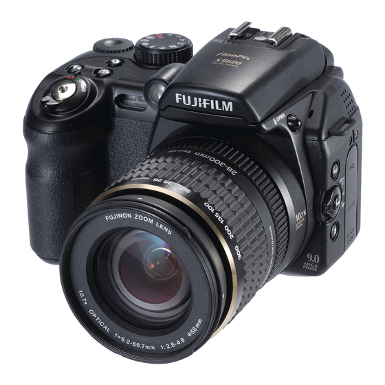
Page 13: Names Of External Components
1. General FinePix S9100/S9600 Service Manual 1-3. Names of External Components Power switch Hot shoe AF-assist illuminator / Self-timer lamp Power-OFF External AF sensor Playback mode Shutter button Photography mode Release socket Exposure compensation button Flash button Continuous shooting button... - Page 14 1. General FinePix S9100/S9600 Service Manual Flash Flash pop-up button Microphone Strap mount Focus ring Speaker INFO (information check) Zoom ring button Terminal cover USB socket (mini-B) A/V OUT (Audio / Visual output) Lens hood socket DC IN 5V (power input) socket...
-
Page 15: Disassembly
2. Disassembly FinePix S9100/S9600 Service Manual 2. Disassembly 2-1. Names of internal Components HINGE CONST ASSY CASE R SPEAKER ASSY KEY PWB ASSY FLASH CONST ASSY CASE TOP MAIN PWB ASSY EVF UNIT CONST TOP FPC CONST AF SENSOR UNIT... -
Page 16: Removing The Const Case Top
2. Disassembly FinePix S9100/S9600 Service Manual 2-2. Removing the CONST CASE TOP (1) Remove the 2 screws (M1.7 x 5.0). (2) Press BUTTON FLASH to open the flash. (3) Place your thumb on the bottom of the DIAL COMMAND on the CONST CASE TOP and push it up in the direction indicated by the arrow. - Page 17 2. Disassembly FinePix S9100/S9600 Service Manual (5) Pushing the CONST CASE TOP up in the direction of the arrow releases the catch on the front. (6) This releases the catch on the WINDOW AF side at the same time. (7) Remove the TOP FPC in the direction of the arrow.
-
Page 18: Disassembling The Const Case Top
2. Disassembly FinePix S9100/S9600 Service Manual 2-3. Disassembling the CONST CASE TOP (1) Remove the 4 screws (M1.7 x 3.0). (2) Remove the TOP FPC CONST in the direction of the arrow. [Assembly] Assemble by performing the disassembly procedure in reverse order. -
Page 19: Removing The Case R Const
2. Disassembly FinePix S9100/S9600 Service Manual 2-4. Removing the CASE R CONST (1) Remove the screw (M1.7 x 5.0). (2) Remove the screw (M1.7 x 3.5). (3) Remove the 2 screws (M1.7 x 4.0). (4) Remove the 6 screws (M1.7 x 3.5). - Page 20 2. Disassembly FinePix S9100/S9600 Service Manual (6) Release the PLATE REAR catch and the catch inside the left side. (7) Slowly pull off the CASE R CONST to the rear. (8) Remove the SPEAKER ASSY connector. (9) Remove the SHOE WIRE HARNESS connector.
- Page 21 2. Disassembly FinePix S9100/S9600 Service Manual (10) After removing the connectors, remove the LCD FPC and KEY-MAIN FPC. (11) Remove the COVER JACK. [Assembly] Assemble by performing the disassembly procedure in reverse order. [Notes on assembly] (1) Ensure that the harness is not pinched in the PLATE REAR during assembly.
-
Page 22: Disassembling The Case R Const Case
2. Disassembly FinePix S9100/S9600 Service Manual 2-5. Disassembling the CASE R CONST CASE (1) Remove the 5 screws (M1.7 x 7.0). (2) Remove the 2 screws (M1.7 x 2.5). (3) Remove the PLATE EMI. (4) Take out the SPEAKER ASSY in the direction of the arrow. - Page 23 2. Disassembly FinePix S9100/S9600 Service Manual [Notes on assembly] Ensure that the COVER CARD is open when assembling the KEY PWB. (This prevents damage to SW752.) [Notes on assembly] Run the SHOE CONST leads along the PLATE REAR, as shown in the figure on the right.
-
Page 24: Removing The Hinge Const
2. Disassembly FinePix S9100/S9600 Service Manual 2-6. Removing the HINGE CONST (1) Remove the 2 screws (M1.7 x 4.0). (2) Remove the 5 screws (M1.7 x 2.0). (3) Run the LCD FPC to the inside. (4) Pull the COVER FPC off in the direction of the arrow. - Page 25 2. Disassembly FinePix S9100/S9600 Service Manual [Assembly] Assemble by performing the disassembly procedure in reverse order. [Notes on assembly] To attach the UNIT HINGE to the CASE LCD R. (1) Engage the catches. (2) Fit the flexible cable onto the catches.
-
Page 26: Removing The Main Pwb Assy/Dcst Pwb Assy
2. Disassembly FinePix S9100/S9600 Service Manual 2-7. Removing the MAIN PWB ASSY/DCST PWB ASSY (1) Remove four WIRE HARNESS. (2) Remove the EVF FPC. (3) Remove the EVF UNIT CONST in the direction of the arrow. (4) Remove the AF SENSOR FPC. - Page 27 2. Disassembly FinePix S9100/S9600 Service Manual (13) Remove the BATT HOLDER connector. (14) Remove the SYNCHRO TERMINAL connector. To BATT HOLDER To SYNCHRO TERMINAL Take care not to touch the main capacitor terminal as this could result in an electric shock.
- Page 28 2. Disassembly FinePix S9100/S9600 Service Manual [Notes on assembling the MAIN PWB ASSY/DCST PWB ASSY] If the screw holes in the DC JACK and FRAME are misaligned as shown in the figure below, the PWB is out of position. Misalignment If this is the case, lifting the DCST PWB ASSY at point (1) will produce a clicking noise.
- Page 29 2. Disassembly FinePix S9100/S9600 Service Manual [Notes on assembling the WIRE HARNESS for the FLASH CONST] (1) To ensure that the harness is not pinched when the FLASH TOP opens and closes, arrange the wires so that they form a 4-strand twisted cable.
-
Page 30: Removing The Frame Pwb/Frame Batt
2. Disassembly FinePix S9100/S9600 Service Manual 2-8. Removing the FRAME PWB/FRAME BATT (1) Remove the screw (M1.7 x 5.0). (2) Remove the screw (M1.7 x 4.0). (3) Remove the screw (M1.7 x 5.0). (4) Remove the FRAME BATT. (5) Pull off the BASE TRIPOD in the direction of the arrow. - Page 31 2. Disassembly FinePix S9100/S9600 Service Manual (13) Remove the 2 screws (M1.7 x 4.0). (14) Pull the FLASH CONST off in the direction of the arrow. (15) Remove the 2 screws (M1.4 x 4.0). (16) Pull the SW UNIT off in the direction of the arrow.
- Page 32 2. Disassembly FinePix S9100/S9600 Service Manual [Notes on assembly] (1) Ensure that the GATE section of the BUTTON FLASH is upwards when assembled. GATE (2) When assembling the SW UNIT, set the LEVER FOCUS to “S” and assemble with the SW UNIT lever set to the center position.
- Page 33 2. Disassembly FinePix S9100/S9600 Service Manual (4) Ensure that the SYNCHRO TERMINAL harness is not pinched between the CASE F rib and the BATT HOLDER. (5) Run the 2 WIRE HARNESS pairs through the BATT HOLDER catches as shown in the figure.
-
Page 34: Removing The Af Sensor Unit
2. Disassembly FinePix S9100/S9600 Service Manual 2-10. Removing the AF SENSOR UNIT [Notes] SENSOR ADJUSTER Hold the base of the AF SENSOR UNIT when working on Do not touch the sensor or adjuster. BASE (1) Remove the 2 screws (M1.7 x 4.0). -
Page 35: Location Specifications For Sticking On Sheets
2. Disassembly FinePix S9100/S9600 Service Manual 2-11. Location specifications for sticking on sheets 2-11-1. Sticking the SHEET CF to the MAIN PWB ASSY Stick the sheet in place with the square notches aligned with the slits as shown in the figure. -
Page 36: Sticking The Sheet Emi Side To The Frame Pwb
2. Disassembly FinePix S9100/S9600 Service Manual 2-11-3. Sticking the SHEET EMI SIDE to the FRAME PWB Purpose: To ensure conductivity between the two metal plates Fold the sheet into upper and lower halves and ensure that the sheet does not protrude beyond either of the metal plates. -
Page 37: Sticking The Sheet Emi-Cd To The Ccd Fpc
2. Disassembly FinePix S9100/S9600 Service Manual 2-11-5. Sticking the SHEET EMI-CD to the CCD FPC Purpose: To cover the CCD FPC with a conducting sheet to ensure that it makes contact with the CCD metal backing plate Pressure must NOT be Fold this section over. -
Page 38: Sheet Emi-Frame
2. Disassembly FinePix S9100/S9600 Service Manual 2-11-7. Sticking K TAPE onto the LCD FPC Purpose: To protect the LCD FPC Apply the K TAPE (19 x 23 mm) from a position The entire tape is folded no more than 1 mm from back over on both sides. -
Page 39: Sticking The Sheet Emi-Frame To The Frame Pwb/Ccd Plate
2. Disassembly FinePix S9100/S9600 Service Manual 2-11-9. Sticking the SHEET EMI-FRAME to the FRAME PWB/CCD plate Purpose: To insulate the conducting sheet Apply the K TAPE (19 x 17 mm) so that the conducting sheet in this section is completely covered and hidden. -
Page 40: Sticking The Sheet Graphite To The Holder Lens/Ccd Plate
2. Disassembly FinePix S9100/S9600 Service Manual 2-11-10. Sticking the SHEET GRAPHITE to the HOLDER LENS/CCD plate Purpose: To connect area A and CCD backing plate B with the SHEET GRAPHITE (to release heat from the CCD) Do not press on this area when applying the sheet (to prevent FPC breakage). - Page 41 2. Disassembly FinePix S9100/S9600 Service Manual 2-11-11. Sticking the GASKET to the UNIT HINGE BB19729-100 2-11-12. Sticking K TAPE to the MAIN PWB ASSY Purpose: To prevent short-circuits with the MAIN PWB ASSY ZS00116-100 Apply the K TAPE (19 x 19 mm) so that these 3 components are all covered and hidden.
- Page 42 2. Disassembly FinePix S9100/S9600 Service Manual MEMO 2-28...
-
Page 43: Schematics
3. Schematics FinePix S9100/S9600 Service Manual 3. Schematics 3-1. Cautions <Cautions when replacing parts> • Do not reuse removed parts. Always use new parts. • Note that the negative side of tantalum condensers is readily damaged by heat. • Except for chemical condensers and tantalum condensers, voltage is not displayed on condensers with a voltage resistance of 50V or less. -
Page 44: Description Of Main Block Functions
3-3-1. Technical Overview Featuring the "Super CCD Honeycom V HR" and the "Real Photo Engine", the FinePix S9100/S9600 not only gives you images with superb resolution and minimal noise, it is also highly effective at high sensitivities, providing images with little or no camera shake or subject blurring even in low-light conditions and telephoto shots. -
Page 45: Block Diagram
3. Schematics FinePix S9100/S9600 Service Manual 3-4. Block Diagram MAIN PWB JTAG CF Card IC204 FF4193 3.3V Operation AF Sensor IST,GS1,GS2,END,S/S,CP Micro Drive Slot (50PIN) IBFC AUTO RECC IC103 AD9996 BCS_RESET xD PictureCard 10.7xZOOM LENS HA-CCD xD Card 3.3V Operation... -
Page 46: Overall Connection Diagram
3. Schematics FinePix S9100/S9600 Service Manual 3-5. Overall connection Diagram... -
Page 47: Circuit Diagrams
3. Schematics FinePix S9100/S9600 Service Manual 3-6. Circuit Diagrams 3-6-1. CAMERA BLOCK... -
Page 48: Dcdc Block
3. Schematics FinePix S9100/S9600 Service Manual 3-6-2. DCDC BLOCK... -
Page 49: Key Block
3. Schematics FinePix S9100/S9600 Service Manual 3-6-3. KEY BLOCK... -
Page 50: Lcd/Evf Block
3. Schematics FinePix S9100/S9600 Service Manual 3-6-4. LCD/EVF BLOCK... -
Page 51: Process Block
3. Schematics FinePix S9100/S9600 Service Manual 3-6-5. PROCESS BLOCK... - Page 52 3. Schematics FinePix S9100/S9600 Service Manual MEMO 3-10...
-
Page 53: Audio Block
3. Schematics FinePix S9100/S9600 Service Manual 3-6-6. AUDIO BLOCK 3-11... -
Page 54: Ccd Fpc Block
3. Schematics FinePix S9100/S9600 Service Manual 3-6-7. CCD FPC BLOCK 3-12... -
Page 55: Ips2 Block
3. Schematics FinePix S9100/S9600 Service Manual 3-6-8. IPS2 BLOCK 3-13... -
Page 56: Main I/F Block
3. Schematics FinePix S9100/S9600 Service Manual 3-6-9. MAIN I/F BLOCK 3-14... -
Page 57: Motor Block
3. Schematics FinePix S9100/S9600 Service Manual 3-6-10. MOTOR BLOCK 3-15... -
Page 58: Strb Block
3. Schematics FinePix S9100/S9600 Service Manual 3-6-11. STRB BLOCK 3-6-12. LCD CITI BLOCK 3-16... -
Page 59: Top Fpc Block
3. Schematics FinePix S9100/S9600 Service Manual 3-6-13. TOP FPC BLOCK 3-17... -
Page 60: Ml Fpc Block
3. Schematics FinePix S9100/S9600 Service Manual 3-6-14. ML FPC BLOCK 3-6-15. STSW BLOCK 3-6-16. TRG BLOCK 3-18... -
Page 61: Mounted Parts Diagrams
3. Schematics FinePix S9100/S9600 Service Manual 3-7. Mounted Parts Diagrams 3-7-1. CCD PWB ASSY 3-19... -
Page 62: Key Pwb Assy
3. Schematics FinePix S9100/S9600 Service Manual 3-7-2. KEY PWB ASSY <SIDE A> 3-20... - Page 63 3. Schematics FinePix S9100/S9600 Service Manual <SIDE B> 3-21...
-
Page 64: Led Pwb Assy
3. Schematics FinePix S9100/S9600 Service Manual 3-7-3. LED PWB ASSY <SIDE A> <SIDE B> 3-22... -
Page 65: Ml Pwb Assy
3. Schematics FinePix S9100/S9600 Service Manual 3-7-4. ML PWB ASSY 3-7-5. TRG PWB ASSY 3-23... -
Page 66: Stsw Pwb Assy
3. Schematics FinePix S9100/S9600 Service Manual 3-7-6. STSW PWB ASSY 3-7-7. TOP PWB ASSY 3-24... -
Page 67: Dcst Pwb Assy
3. Schematics FinePix S9100/S9600 Service Manual 3-7-8. DCST PWB ASSY 3-25... -
Page 68: Main Pwb Assy
3. Schematics FinePix S9100/S9600 Service Manual 3-7-9. MAIN PWB ASSY 3-26... -
Page 69: Adjustments
4. Adjustments FinePix S9100/S9600 Service Manual 4. Adjustments 4-1. Important point Adjustment when Replacing Major Parts Adjust the item shown by in the table below at the part replacement of LENS ASSY, MAIN PWB, DCST PWB, AF-SENSOR and FLASH CONST. (Other part replacements need not be adjusted.) -
Page 70: Use Jig List
AF Sensor adjustment Common with the FinePix M603 *1: Please downloaded from Web server (http://fujifilm-di.intranets.com/). *2: Select one the power cable suitable each country. *3: S9000/9500 Zoom drive jig is a Jig by which the thing that the zoom position match of the shading compensation adjustment... -
Page 71: Calibration Method Of Pattern Box
4. Adjustments FinePix S9100/S9600 Service Manual 4-4. Calibration method of pattern box < Use the pattern box for Camera adjustment > Turn on the power supply in the pattern box. Afterwards, wait for about ten minutes so that the source of Pattern BOX light may stabilize. -
Page 72: Installation Of Dsc Jig Driver
4. Adjustments FinePix S9100/S9600 Service Manual <Step3> My Computer When all the folders have been copied to the C:drive, double- click on [C:\ FxS9100_9600_W\ FFW.exe] to start the 3.5inch FD(A:) adjustment software. (C:) (Note) ZJ01001-100 * Specify the preservation drive for C drive if it... -
Page 73: Initial Settings Of The Adjustment Software
4. Adjustments FinePix S9100/S9600 Service Manual 4-6. Initial Settings of the Adjustment Software * The initial settings are already written in the "FFW.ini" file, therefore perform the following procedure to the letter. Note that, if you change file names, the software will not start up. - Page 74 4. Adjustments FinePix S9100/S9600 Service Manual <Step 3> Select the "EVR&Comm." tab ([1] in Fig. 4-6-3) in the "Customize" dialog box that appears. Set the "EVR&Comm." items as follows. Item Details etc (-V2) Check LANC page Check <Fig. 4-6-3> <Step 4>...
- Page 75 4. Adjustments FinePix S9100/S9600 Service Manual [ Setting when S9000/9500 Zoom drive jig is used ] Always use this jig for AF adjustment. But it can be used for either manual or automatic adjustment for CCD Line Defect and shading.
-
Page 76: Starting The Adjustment Software
4. Adjustments FinePix S9100/S9600 Service Manual 4-7. Starting the Adjustment Software <Step 1> Double-click on [FFW.EXE] (Fig. 4-5-3) in the folder copied to the C drive (see ‘4-5-1. Various downloading software decompressions, preservation methods and notes’) to display the adjustment software start-up screen. - Page 77 4. Adjustments FinePix S9100/S9600 Service Manual <Step 4> FinePix S9100_9600_W Adjustment Software < Camera Jig Mode Setup Procedure > 1. Set the mode to the [AUTO] mode. 2. Open the Card cover. 3. Connect the USB cable. 4. Supply 5.0+-0.1V to the camera using the [DC Jack cable] as appropriate for the adjustment details.
- Page 78 4. Adjustments FinePix S9100/S9600 Service Manual <Step 6> FinePix S9100_9600_W adjustment item select screen 0. [ R ] : Flash memory reset *Only use for when the MAIN PWB has been replaced. 1. [ F 9 ] : AF Sensor Adjustment 2.
-
Page 79: R] : Flash Memory Reset
4. Adjustments FinePix S9100/S9600 Service Manual 4-8. [R] : Flash Memory Reset <Note> Only reset the flash memory when the MAIN PWB ASSY has been replaced. When the MAIN PWB ASSY has been replaced, always reset the flash memory before making any other adjustments. - Page 80 4. Adjustments FinePix S9100/S9600 Service Manual <Step 2> Flash memory reset (EVR) < Attention > When the MAIN PWB ASSY has been replaced, always reset the flash memory before making any other adjustments. Only reset the flash memory when the MAIN PWB ASSY has been replaced.
-
Page 81: F9] : Af-Sensor Adjustment
4. Adjustments FinePix S9100/S9600 Service Manual 4-9. [F9] : AF-Sensor Adjustment < Setup for AF-Sensor Adjustment> (1) Prepare as follows using non-defective equipment. (2) Mount the camera on a tripod, and place the S9000/S9500 AF-1mV Chart (for 1005mm) at a distance of 1005mm from the front face of the AF-Sensor window. - Page 82 4. Adjustments FinePix S9100/S9600 Service Manual <Cautions During Adjustment> Adjust the AF-Sensor when the AF-Sensor unit detaches or replaces it from the camera. As the accuracy of AF distance measurement with the AF-Sensor unit changes with temperature, this adjustment should be performed immediately after the camera power supply is switched ON.
- Page 83 4. Adjustments FinePix S9100/S9600 Service Manual <Step 3> When preparations are complete, press the Enter key. AF-Sensor vertical Adjustment (1) Place the S9000/S9500 AF-1mV Chart at a distance of 1005+-5mm from the Zoom-Ring edge. (2) Don't set the conversion lens yet.
- Page 84 4. Adjustments FinePix S9100/S9600 Service Manual <Step 4> Adjust the screen angle so that the 'Red circle' symbol displayed on the TV monitor is within the circle. When preparations are complete, press the Enter key. AF-Sensor vertical Adjustment < Adjustment preparation >...
- Page 85 4. Adjustments FinePix S9100/S9600 Service Manual <Step 5> Adjust the AF-Sensor by turning the AF-Sensor Adjustment screw (silver colored) with a + screwdriver in accordance with the instructions from the adjustment software. AF-Sensor vertical Adjustment THRE1 MAX = Turn the AF-Sensor vertica adjustment screw.
- Page 86 4. Adjustments FinePix S9100/S9600 Service Manual When [Adjustment OK!] appears on the screen, press the [Enter] key on the PC and make adjustment preparations in accordance with the instructions from the adjustment software. AF-Sensor vertical adjustment THRE1 MAX = Turn the AF-Sensor vertical adjustment screw.
- Page 87 4. Adjustments FinePix S9100/S9600 Service Manual <Step 7> AF-Sensor horizontal adjustment THRE1 MAX = Turn the AF-Sensor horizontal adjustment screw. Press the [Enter] of PC when the adjustment is completed. TURN CW Press [0]key of PC when you cannot complete the adjustment.
- Page 88 4. Adjustments FinePix S9100/S9600 Service Manual When [Adjustment OK!] appears on the screen, press the [Enter] key on the PC and make adjustment preparations in accordance with the instructions from the adjustment software. AF-Sensor horizontal Adjustment THRE1 MAX = Turn the AF-Sensor horizontal adjustment screw.
- Page 89 4. Adjustments FinePix S9100/S9600 Service Manual <Step 9> Prepare the AF sensor Linearity adjustment according to the instruction of the adjustment software. AF-1mH chart setup distance : 1005mm+/-5mm from front Zoom-Ring edge. Chart surface reflective luminance : 7.0Ev to 9.0Ev.
- Page 90 4. Adjustments FinePix S9100/S9600 Service Manual <Step 10> Prepare the AF sensor Linearity adjustment (900mm) according to the instruction of the adjustment software. 900mm conversion lens setup distance : 105mm+/-5mm from Zoom-Ring edge. Chart surface reflective luminance : 7.0Ev to 9.0Ev.
- Page 91 4. Adjustments FinePix S9100/S9600 Service Manual <Step 12> The AF-Sensor adjustment is completed. Press the [Enter] key to return to the Adjustment Item selection Screen. <Fig. 4-9-13> 4-23...
-
Page 92: F4] : Ccd Data Input
4. Adjustments FinePix S9100/S9600 Service Manual 4-10. [F4] : CCD Data Input CCD data input is required when the LENS ASSY or MAIN PWB ASSY is replaced. [Method of acquiring CCD data] 05001A0 1. When you exchange LENS ASSY 0179AC -->... - Page 93 4. Adjustments FinePix S9100/S9600 Service Manual < Adjustment > <Step 1> Select [F4] CCD Defect Data Input on the [Adjustment Items Select] screen. --> The [CCD Defect Data Input Start] screen appears. <Step 2> Run the adjustment in accordance with the instructions on the screen.
-
Page 94: F5] : Camera Adjustment
4. Adjustments FinePix S9100/S9600 Service Manual 4-11. [F5] : Camera Adjustment (shutter adjustment, adjustment for reduced aperture sensitivity, ISO sensitivity adjustment, white balance adjustment, AE adjustment, offset level adjustment) < Setup for Camera Adjustment> < Importance! > 1. Calibrate the pattern box before adjusting the camera. - Page 95 4. Adjustments FinePix S9100/S9600 Service Manual <Step 3> Shutter adjustment (1) Set the distance between the camera and pattern box. (2) The LB140 filter is not placed in front of the lens. When preparations are complete, press the [Enter] key.
- Page 96 4. Adjustments FinePix S9100/S9600 Service Manual <Step 5> OFD dependence sensitivity decreasing rate adjustment (1) Set the distance between the camera and pattern box. (2) The LB140 filter is not placed in front of the lens. When preparations are complete, press the [Enter] key.
- Page 97 4. Adjustments FinePix S9100/S9600 Service Manual <Step 7> WB adjustment without filter (1) Set the distance between the camera and pattern box. (2) Remove the LB140 filter from front of the lens. When preparations are complete, press the [Enter] key.
- Page 98 4. Adjustments FinePix S9100/S9600 Service Manual <Step 9> WB adjustment without filter (avobe ISO800) (1) Set the distance between the camera and pattern box. (2) Remove the LB140 filter from front of the lens. When preparations are complete, press the [Enter] key.
-
Page 99: C ] : Ccd Line Defect Adjustment
4. Adjustments FinePix S9100/S9600 Service Manual 4-12. [ C ] : CCD Line Defect Adjustment <Setup for CCD Line Defect Adjustmen> Set up DPC-R1 to the computer as explained by instructing CCD Line Defect Adjustment. After Camera adjustment and CCD data input are complete, this adjustment is done. - Page 100 4. Adjustments FinePix S9100/S9600 Service Manual <Step 2> Run the adjustment in accordance with the instructions on the screen. CCD Line defect adjustment < CCD Line Defect Adjustment Preparations > (1) Insert the xD card of 64MB or more that has been formatted in the camera.
- Page 101 4. Adjustments FinePix S9100/S9600 Service Manual <Step 4> FinePix S9100/9600 PC for adjustments and checks xD-Picture Card 64MB or more) Regurated Digital Voltmeter Power supply DPC-R1 USB cable DC JACK Power supply cable jig COPY DSCF0001.CM From ‘100_FUJI’ to ‘MS3931’...
- Page 102 4. Adjustments FinePix S9100/S9600 Service Manual <Step 5> 50010179 CCD Line defect adjustment < Preparations > (1) Enter the 8-digit ccdserial number in the CCD Data Input dialog box. The file extrension need not be entered. (2) Insert the floppy disk in the A: drive (floppy disk drive) on the PC.
-
Page 103: S ]: Shading Compensation Adjustment
4. Adjustments FinePix S9100/S9600 Service Manual 4-13. [ S ]: Shading compensation adjustment (Shading compensation adjustment) < Setup for Shading compensation adjustment > < Importance! > 1. Calibrate the pattern box before adjusting the shading. 2. Ensure that shading adjustment is carried out in dark surroundings (ideally in a darkroom environment). - Page 104 4. Adjustments FinePix S9100/S9600 Service Manual <Step 2> Set the zoom position in Zoom position Darken the surrounding, and press enter key of PC. <Fig. 4-13-2> --> The [Zoom setting of [12] position] screen appears. <Step 3> Set the zoom position in...
- Page 105 4. Adjustments FinePix S9100/S9600 Service Manual <Step 4> Set the zoom position in Zoom position Out of alignment to the zoom position <Fig. 4-13-4> --> The [Zoom setting of [27] position] screen appears. <Step 5> Set the zoom position in...
- Page 106 4. Adjustments FinePix S9100/S9600 Service Manual <Step 6> Set the zoom position in Zoom position Out of alignment to the zoom position <Fig. 4-13-6> --> The [Zoom setting of [1] position] screen appears. <Step 7> Set the zoom position in...
- Page 107 4. Adjustments FinePix S9100/S9600 Service Manual <Step 8> Set the zoom position in Zoom position Out of alignment to the zoom position <Fig. 4-13-8> --> Write the adjustment data to the flash ROM when adjustment has been completed correctly. --> The [Shading compensation adjustment Complete] screen appears.
-
Page 108: F6] : Af Adjustment
4. Adjustments FinePix S9100/S9600 Service Manual 4-14. [F6] : AF Adjustment <Setup for AF Adjustment> (1) Set the camera in the zoom drive jig. (2) Set up the camera so that the distance from the multi-stripe chart to the front edge of the camera's filter ring is 897.3±1 (3) Illuminate the AF chart with a light source. - Page 109 4. Adjustments FinePix S9100/S9600 Service Manual <Step 2> Run the adjustment in accordance with the instructions on the screen. <Note> Always use a 800mm conversion lens. AF Adjustment < AF Adjustment Preparations > (1) Prepare a 800mm conversion lens. (2) Prepare a S9100/S9600 Multi-stripe chart.
- Page 110 4. Adjustments FinePix S9100/S9600 Service Manual <Step 4> AF Adjustment (900mm) (1) Remove the conversion lens. (2) Adjust the position of the camera so that the center of the S9100/S9600 Multi-stripe chart is displayed in the camera LCD. When preparations (1) - (2) are complete, press the [Enter] key.
-
Page 111: F7] : Flash Adjustment
4. Adjustments FinePix S9100/S9600 Service Manual 4-15. [F7] : Flash Adjustment <Setup for Flash Adjustment> (1) As flash adjustment is readily affected by external light, ensure that the vicinity of the gray chart is very dark. (2) Ensure that distance is measured from the front of the camera during flash adjustment. - Page 112 4. Adjustments FinePix S9100/S9600 Service Manual <Step 3> Flash Adjustment (1) Adjust brightness so that the periphery of the gray chart is as dark as possible. (2) Adjust the camera so that the entire chart is shown on the LCD monitor.
-
Page 113: F1] : Battery Voltage Adjustment
4. Adjustments FinePix S9100/S9600 Service Manual 4-16. [F1] : Battery Voltage Adjustment <Setup for Battery Voltterge Adjustment> (1) When adjusting the battery voltage, supply power (5.0V) to the camera from the [Power Cable Jig] before setting the jig mode. (2) Always measure input voltage in the vicinity of the DC IN terminal. - Page 114 4. Adjustments FinePix S9100/S9600 Service Manual <Step 2> Run the adjustment in accordance with the instructions on the screen. Battery Voltage Adjustment <Preparations> 1. Check that the Power Cable Jig and the camera are connected. *If not, return to the Jig Mode Setup screen, and connect the Power Cable Jig and the camera.
- Page 115 4. Adjustments FinePix S9100/S9600 Service Manual <Step 4> Battery Voltage Adjustment (1) Supply 4.50V (+0.02V/-0.00V). When preparations are complete, press the [Enter] key. Result= (2) Supply 4.00V (+0.02V/-0.00V). When preparations are complete, press the [Enter] key. <Fig. 4-16-3> —> The [7.20V Input] screen appears.
- Page 116 4. Adjustments FinePix S9100/S9600 Service Manual <Step 6> Battery Voltage Adjustment (1) Supply 4.50V (+0.02V/-0.00V). When preparations are complete, press the [Enter] key. Result= (2) Supply 4.00V (+0.02V/-0.00V). When preparations are complete, press the [Enter] key. Result= (3) Supply 7.20V (+0.02V/-0.00V).
-
Page 117: F2] : Mode Dial Adjustment
4. Adjustments FinePix S9100/S9600 Service Manual 4-17. [F2] : Mode Dial Adjustment <Setup for Mode Dial Adjustment> (1) When adjusting the Mode Dial, supply power (5.0V) to the camera from the [Power Cable Jig] before setting the jig mode. (2) Always measure input voltage in the vicinity of the DC IN terminal. - Page 118 4. Adjustments FinePix S9100/S9600 Service Manual <Step 2> Mode Dial Adjustment (1) Set the mode dial to [AUTO]. (2) Please input 5.00+-0.01V from DC-IN Jack. Press the [Enter] key of PC after setting the camera. Press [1] key to PC when not proceeding to the next step.
-
Page 119: F11] : Video Adjustment
4. Adjustments FinePix S9100/S9600 Service Manual 4-18. [F11] : Video Adjustment <Setup for Video Adjustment> (1) Set up the PCI-2746C board in the computer as explained in the instructions for the video adjustment jig. (2) If the waveform of the brightness signal (Y) or color signal (C) does not appear in the “WAVE No. 0” window during adjustments, check the connections of the video adjustment jig. - Page 120 4. Adjustments FinePix S9100/S9600 Service Manual <Step 2> Run the adjustment in accordance with the instructions on the screen. Video Adjustment < VIDEO Adjustment Preparations > (1) Connect the camera and video adj. jig with the video cable. (2) Confirm Video jig is connected with the video cable.
-
Page 121: F8] : Firmware Download
4. Adjustments FinePix S9100/S9600 Service Manual 4-19. [F8] : Firmware Download Attention : When the download of the firmware is needed, FUJI SERVICE BULLETIN is contacted from FTYO/QA. Till then, disregard this item. <Setup for Firmware Download> FinePix S9100/S9600 PC for adjustment and checks... - Page 122 4. Adjustments FinePix S9100/S9600 Service Manual <Step 3> Firmware download is completed (1) Remove the DC Jack cable from the camera. (2) Turn off power lever switch. (3) Reconnect DC Jack cable. (4) Switch camera power ON while pressing the shutter button.
-
Page 123: F12] : End Setting
3. USB ID write details 1) USB ID write requires that the USB device (in this case FinePix S9100/S9600) be unique throughout the world. For this reason, each device has a unique ID as determined by the USB standard. If multiple devices with the same USB ID are connected to a single PC, the PC will be unable to identify each USB device, thus preventing operation. - Page 124 4. Adjustments FinePix S9100/S9600 Service Manual <Step 1> Select [F12] End Setting on the [Adjustment Items Select] screen. —> The [End Setting Description] screen appears. <Step 2> Run the adjustment in accordance with the instructions on the screen. End Setting...
- Page 125 4. Adjustments FinePix S9100/S9600 Service Manual <Step 4> Destination setting The destination is selected from an undermentioned list, according to third character from left side of the serial number. The third character <A> FinePix S9100 J-model 0 to 9 <B> FinePix S9100 US-model A to H,J,K <C>...
- Page 126 4. Adjustments FinePix S9100/S9600 Service Manual <Step 6> USB ID Selected U.S.A.. Press the [Enter] key! <Fig. 4-20-5> —> The [FinePix S9100_9600 Adjustment End] screen appears. <Step 7> FinePix S9100_9600 Adjustment is completed. 1) Remove USB cable from the camera.
-
Page 127: Inspection
5. Inspection FinePix S9100/S9600 Service Manual 5. Inspection 5-1. Required Measuring Equipment Measuring equipment Remarks Power supply AC adapter (AC-5V), Regurated power supply Digital voltmeter For general use Ammeter For general use (able to measure 1mA or less) POWER CABLE JIG... -
Page 128: Inspection And Factory Settings
5. Inspection FinePix S9100/S9600 Service Manual 5-3. Inspection and Factory Settings Sequemnce Item Mode Preparations for adjustment Method of adjustment Measuring Measurement points (measurement points, subject, other) (VRs, waveforms, required values) equipment and jigs (VRs, positions) External visual Camera observation... - Page 129 5. Inspection FinePix S9100/S9600 Service Manual Sequemnce Item Mode Preparations for adjustment Method of adjustment Measuring Measurement points (measurement points, subject, other) (VRs, waveforms, required values) equipment and jigs (VRs, positions) Resolution check Auto mode (1) Use a macro resolution...
- Page 130 5. Inspection FinePix S9100/S9600 Service Manual Sequemnce Item Mode Preparations for adjustment Method of adjustment Measuring Measurement points (measurement points, subject, other) (VRs, waveforms, required values) equipment and jigs (VRs, positions) Movie/audio Movie (1) Set the Mode dial to (1) Check that “STANDBY”...
- Page 131 5. Inspection FinePix S9100/S9600 Service Manual Sequemnce Item Mode Preparations for adjustment Method of adjustment Measuring Measurement points (measurement points, subject, other) (VRs, waveforms, required values) equipment and jigs (VRs, positions) LCD dust/defect Playback (1) Insert a standard xD- ZJ00885-100 check Picture card.
- Page 132 5. Inspection FinePix S9100/S9600 Service Manual Sequemnce Item Mode Preparations for adjustment Method of adjustment Measuring Measurement points (measurement points, subject, other) (VRs, waveforms, required values) equipment and jigs (VRs, positions) Current Auto mode (1) Connect the power ZJ00580-100 consumption...
- Page 133 5. Inspection FinePix S9100/S9600 Service Manual Sequemnce Item Mode Preparations for adjustment Method of adjustment Measuring Measurement points (measurement points, subject, other) (VRs, waveforms, required values) equipment and jigs (VRs, positions) *Setting and clearing date (1) Connect the USB cablefrom the PC to the camera (ensure that the PC isswitched ON).
-
Page 134: Resolution Checking
5. Inspection FinePix S9100/S9600 Service Manual 5-4. Resolution Checking <Step 1> Fluorescent light stand Refer to the settings for resolution checking in the figure at right and set up the camera and the high-resolution chart. High-resolution chart Use a light source to illuminate the high-resolution chart so ZJ00398-100 that the surface brightness of the chart is 9.0 to 11.5 EV. - Page 135 5. Inspection FinePix S9100/S9600 Service Manual The centrally enlarged image (Fig. 5-4-4 (1)) is normal if a resolution of 1400 lines can be confirmed. Use the same procedure to check the resolution of peripherally enlarged versions (Fig. 5-4-5 (1)) of the resolution checking image (Fig.
- Page 136 5. Inspection FinePix S9100/S9600 Service Manual MEMO 5-10...
-
Page 137: Parts List
6. Parts List FinePix S9100/S9600 Service Manual 6. Parts List 6-1. Packing and Accessories 6-1-1. US-model A107 A108 A114 A113 A112 A104 A122 A109 A117 A121 A110 A120 A119 A118 A111 A116 A106 A115 A102 A103 A101 A105 Ref No. -
Page 138: Jp-Model
6. Parts List FinePix S9100/S9600 Service Manual 6-1-2. JP-model A107 A108 A114 A113 A112 A104 A109 A117 A110 A119 A116 A111 A115 A106 A102 A103 A101 A118 A105 Ref No. Parts No. Description Comment Ref No. Parts No. Description Comment... -
Page 139: Eu-Model
6. Parts List FinePix S9100/S9600 Service Manual 6-1-3. EU-model A107 A108 A114 A113 A112 A124 A104 A123 A122 A109 A117 A121 A110 A120 A119 A118 A111 A116 A106 A115 A102 A103 A101 A105 A125 N.S.=Not Supply Ref No. Parts No. -
Page 140: Eg-Model
6. Parts List FinePix S9100/S9600 Service Manual 6-1-4. EG-model A107 A108 A114 A113 A112 A104 A120 A109 A117 A110 A119 A118 A111 A116 A106 A115 A102 A103 A101 A105 A121 Ref No. Parts No. Description Comment Ref No. Parts No. -
Page 141: Ee-Model
6. Parts List FinePix S9100/S9600 Service Manual 6-1-5. EE-model A107 A108 A114 A113 A112 A104 A109 A117 A110 A119 A118 A111 A116 A106 A115 A102 A103 A101 A105 A120 Ref No. Parts No. Description Comment A101 FZ06681-100 UNITARY BOX A102... -
Page 142: As-Model
6. Parts List FinePix S9100/S9600 Service Manual 6-1-6. AS-model A107 A108 A114 A113 A112 A104 A109 A117 A110 A119 A118 A111 A116 A106 A115 A102 A103 A101 A105 A120 Ref No. Parts No. Description Comment A101 FZ06681-100 UNITARY BOX A102... -
Page 143: Ch-Model
6. Parts List FinePix S9100/S9600 Service Manual 6-1-7. CH-model A107 A108 A114 A113 A112 A104 A109 A118 A110 A117 A111 A116 A115 A106 A102 A103 A119 A101 A105 Ref No. Parts No. Description Comment A101 FZ06680-300 UNITARY BOX A102 FZ06406-100... -
Page 144: Cabi Front Block
6. Parts List FinePix S9100/S9600 Service Manual 6-2. Cabi Front Block 6-2-1. US-model M207 M220 M227 M221 M219 M215 M215 M207 M234 M207 M217 M228 M222 M215 M233 M207 M226 M223 M211 M229 M213 M210 M215 K TAPE M202 M229... -
Page 145: Jp-Model
6. Parts List FinePix S9100/S9600 Service Manual 6-2-2. JP-model M207 M220 M227 M221 M219 M215 M215 M207 M234 M207 M217 M228 M222 M215 M233 M207 M226 M223 M211 M229 M213 M210 M215 K TAPE M202 M229 M207 M225 M214 M208 N.S. -
Page 146: Eu/Eg/Ee-Model
6. Parts List FinePix S9100/S9600 Service Manual 6-2-3. EU/EG/EE-model M207 M220 M227 M221 M219 M215 M215 M207 M234 M207 M217 M228 M222 M215 M233 M207 M226 M223 M211 M229 M213 M210 M215 K TAPE M202 M229 M207 M225 M214 M208 N.S. -
Page 147: As/Ch-Model
6. Parts List FinePix S9100/S9600 Service Manual 6-2-4. AS/CH-model M207 M220 M227 M221 M219 M215 M215 M207 M234 M207 M217 M228 M222 M215 M233 M207 M226 M223 M211 M229 M213 M210 M215 K TAPE M202 M229 M207 M225 M214 M208 N.S. -
Page 148: Internal Block
6. Parts List FinePix S9100/S9600 Service Manual 6-3. Internal Block 6-3-1. US/JP-model M311 M309 M301 M308 M308 M310 M326 M303 M307 M323 M323 M315 M304 M325 M308 M324 M308 M304 A D O M313 N.S. M312 M308 M320 M304 M319... -
Page 149: Eu/Eg/Ee/As/Ch-Model
6. Parts List FinePix S9100/S9600 Service Manual 6-3-2. EU/EG/EE/AS/CH-model M311 M309 M301 M308 M308 M310 M326 M303 M307 M323 M323 M315 M304 M325 M308 M324 M308 M304 A D O M313 N.S. M312 M308 M320 M304 M319 M304 M318 M317... -
Page 150: Cabi Rear Block
6. Parts List FinePix S9100/S9600 Service Manual 6-4. Cabi Rear Block M427 M428 M401 M415 M419 M420 M431 M425 M422 M404 M409 M408 M424 K TAPE M407 M406 M413 M403 M421 M418 M405 M414 M416 M432 M430 M423 N.S. M415... -
Page 151: Electrical Parts
6. Parts List FinePix S9100/S9600 Service Manual 6-5. Electrical parts [NOTE] The components indicated by mark are critical for safety. * Due to standardization, replacement in the parts list may be different from When indicated parts by reference number, please include the parts list specified in the circuit or the components used on the set. - Page 152 6. Parts List FinePix S9100/S9600 Service Manual MEMO 6-16...
-
Page 153: Appendix
7. Appendix FinePix S9100/S9600 Service Manual 7. Appendix 7-1. List of Related Technical Updates Issued To ensure that after-sales srevice is performed accuratety, keep a record here of the technical updates issued that cover this device. Technical Update No. Date... - Page 154 FUJI PHOTO FILM CO., LTD. 26-30, Nishiazabu 2-chome, Minato-ku, Tokyo 106-8620, Japan.
Need help?
Do you have a question about the FINEPIX S9100 and is the answer not in the manual?
Questions and answers