Table of Contents
Advertisement
Quick Links
Advertisement
Table of Contents

Related Manuals for Dell Vostro 3010


Summary of Contents for Dell Vostro 3010
- Page 1 Dell Vostro 3010 Owner's Manual Regulatory Model: W09B Regulatory Type: W09B002...
-
Page 2: Notes, Cautions, And Warnings
WARNING: A WARNING indicates a potential for property damage, personal injury, or death. Copyright © 2014 Dell Inc. All rights reserved. This product is protected by U.S. and international copyright and intellectual property laws. Dell ™... -
Page 3: Working On Your Computer
Damage due to servicing that is not authorized by Dell is not covered by your warranty. Read and follow the safety instructions that came with the product. -
Page 4: Recommended Tools
Press and hold the power button while the computer is unplugged to ground the system board. Remove the cover. CAUTION: Before touching anything inside your computer, ground yourself by touching an unpainted metal surface, such as the metal at the back of the computer. While you work, periodically touch an unpainted metal surface to dissipate static electricity, which could harm internal components. -
Page 5: After Working Inside Your Computer
Connect any telephone or network cables to your computer. Connect your computer and all attached devices to their electrical outlets. Turn on your computer. If required, verify that the computer works correctly by running the Dell Diagnostics. -
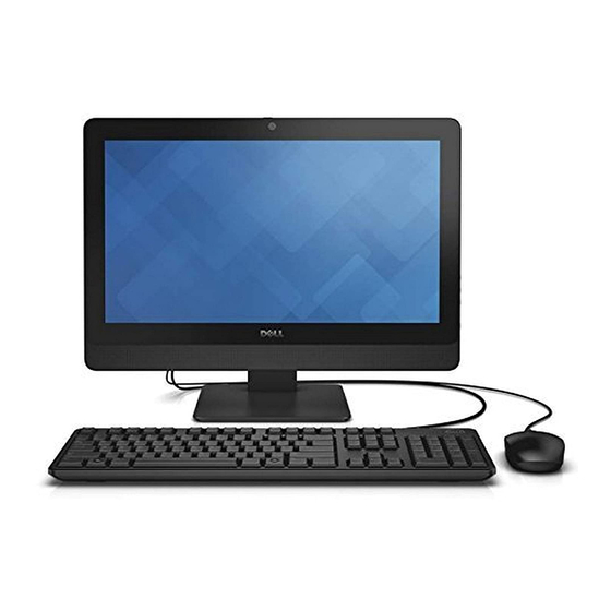
Page 7: System Overview
System Overview Figure 1. Features Microphone Camera Camera-status light Camera-privacy latch Optical drive On-Screen Display (OSD) buttons Hard-drive activity light Power button/Power status light... - Page 8 Stereo speaker 10. USB 2.0 connectors 11. Line-out connector 12. Power-cable connector 13. Network connector 14. Audio connector 15. USB 3.0 connectors 16. Memory card reader Figure 2. Inside View – 1 Memory shield System board shield Speaker cover VESA bracket Hard Drive Power-switch board Convertor board...
-
Page 9: System Board Layout
Figure 3. Inside View – 2 Memory module Coin-cell battery System board Speakers Display bracket WLAN card System Board Layout The following image displays the system board layout of the computer. - Page 10 Memory card reader USB 3.0 connectors Coin-cell battery Audio connector Speaker connector USB 2.0 connectors Line-out connector Power connector Network connector 10. Touch connector 11. Power-switch connector 12. Convertor board connector 13. Hard-drive/Optical-drive power connector 14. Hard-drive connector 15. Optical-drive connector 16.
-
Page 11: Removing And Installing Components
Removing and Installing Components This section provides detailed information on how to remove or install the components from your computer. Removing the Stand Follow the procedures in Before Working Inside Your Computer. Place the computer on a flat surface, display side facing downwards. Pry and remove the panel from the computer. -
Page 12: Installing The Stand
Remove the screws that secure the stand to the computer and remove it from the computer. Installing the Stand Align the stand on the computer, tighten the screws to secure the stand to the computer. Place and press the panel on the computer, until it clicks into place. Follow the procedures in After Working Inside Your Computer. -
Page 13: Installing The Back Cover
Pry up along the edges to release the back cover and remove if from the computer. Installing the Back Cover Align and press the back cover, until it clicks into place. Install the stand. Follow the procedures in After Working Inside Your Computer. Removing the Optical Drive Follow the procedures in Before Working Inside Your Computer. -
Page 14: Installing The Optical Drive
Remove the screw that secures the optical drive to the computer and slide to remove it from the computer. Remove the screws that secure the optical-drive bracket, and remove it from the optical drive. Installing the Optical Drive Tighten the screws to secure the optical-drive bracket to the optical drive. Insert the optical-drive into its slot. -
Page 15: Removing The Hard Drive
Follow the procedures in After Working Inside Your Computer. Removing the Hard Drive Follow the procedures in Before Working Inside Your Computer. Remove the stand. Remove the back cover. Push the hard-drive bracket to release it from its lock and lift the hard drive from one edge. Slide and remove it to access the hard-drive cable. -
Page 16: Installing The Hard Drive
Pry the hard-drive bracket apart to release the hard drive. Remove the hard drive from the hard-drive bracket. Installing the Hard Drive Insert the hard drive into the hard-drive bracket. Connect the hard-drive cable to the hard drive and align the hard drive to its slot on the computer. Install: a) back cover b) stand... -
Page 17: Installing The Convertor Board
Disconnect the cables from the convertor board. Remove the screws and lift the convertor board from the computer. Installing the Convertor Board Tighten the screws to secure the convertor board to the computer. Connect the cables to the convertor board. Install: a) back cover b) stand... -
Page 18: Installing The Memory
Slide and lift the memory shield to remove it from the computer. Pry the retention clips away from the memory module until it pops-up. Lift and remove the memory module from its connector. Installing the Memory NOTE: Please use DIMM 2 slot if there is only one memory module available. Align the notch on the memory-card with the tab in the system-board connector. -
Page 19: Installing The System-Board Shield
Remove the screws that secure the system-board shield to the computer. Lift and remove the system-board shield from the computer. Installing the System-Board Shield Align the system-board shield on the system board. Tighten the screws to secure it to the computer. Install: a) back cover b) stand... -
Page 20: Installing The Heat Sink
Remove the screws that secure the heatsink to the computer. Lift and remove the heatsink from the computer. Installing the Heatsink Align the heatsink on the system board. Tighten the screws to secure it to the computer. Install: a) system-board shield b) back cover c) stand Follow the procedures in After Working Inside Your Computer. - Page 21 Remove the screws that secure the speaker cover to the computer. Release the speaker cover from the computer. Remove the speaker cover from the computer.
-
Page 22: Installing The Speakers
Disconnect the speaker cable from the system board and release the cable from the tabs on the computer. Remove the screws that secure the speakers to the computer. Remove the speakers from the computer. Installing the Speakers Align the speakers on the computer. Tighten the screws to secure them to the computer. Align the speaker cables through their tabs on the computer and connect the speaker cable to the system board. -
Page 23: Removing The Vesa Bracket
Install: a) system-board shield b) back cover c) stand Follow the procedures in After Working Inside Your Computer. Removing the VESA Bracket Follow the procedures in Before Working Inside Your Computer. Remove: a) stand b) back cover Remove the screws that secure the VESA bracket to the computer and remove it from the computer. Installing the VESA Bracket Align the VESA bracket on the computer. -
Page 24: Removing The System Fan
Removing the System Fan Follow the procedures in Before Working Inside Your Computer. Remove: a) stand b) back cover c) System-board shield d) VESA bracket Disconnect the system-fan cable from the system board. Remove the screws that secure the system fan and remove it from the computer. -
Page 25: Installing The Power-Switch Board
Peel the tape that secures the power-switch board to the computer. Lift the power switch board to access the cable. Disconnect the power-switch cable from the power-switch board to remove it from the computer. Installing the Power-Switch Board Insert the power-switch board into its slot on the computer and fix the tape to secure it. Connect the power-switch cable to the power-switch board. -
Page 26: Removing The System Board
Removing the System Board Follow the procedures in Before Working Inside Your Computer. Remove: a) stand b) back cover c) memory d) VESA bracket e) system-board shield f) heatsink g) WLAN card Disconnect the following from the system board: a) camera cable b) LVDS cable c) system-fan cable d) optical-drive cable... -
Page 27: Installing The System Board
Remove the screws that secure the system board to the computer. Slide the system board to release it from the computer. Remove the system board from the computer. Installing the System Board Align the system board on the computer. Tighten the screws to secure the system board to the computer. -
Page 28: Removing The Display Bracket
Connect the following cables to the system board: a) camera cable b) LVDS cable c) system fan cable d) optical-drive cable e) hard-drive cable f) hard-drive/optical-drive power cable g) convertor-board cable h) touch cable (if available) power-switch cable speaker cable Install: a) WLAN card b) heatsink... -
Page 29: Installing The Display Bracket
Release the LVDS, camera, convertor-board cables from their tabs on the display bracket. Remove the screws that secure the display bracket to the computer. Lift and remove the display bracket from the computer. Installing the Display Bracket Align the display bracket on the computer. Tighten the screws to secure the display bracket to the computer. -
Page 30: Removing The Camera
Install: a) system board b) convertor board c) WLAN card d) system fan e) heatsink f) speakers g) system-board shield h) VESA bracket memory hard drive k) optical drive l) back cover m) stand Follow the procedures in After Working Inside Your Computer. Removing the Camera Follow the procedures in Before Working Inside Your Computer. -
Page 31: Installing The Camera
Remove the screws that secure the camera to the computer and release the camera from its slot to access the camera cable. Disconnect the camera cable from the camera and remove the camera from the computer. Installing the Camera Connect the camera cable to the camera. Align the camera into it’s slot and tighten the screws to secure it to the computer... -
Page 32: Removing The Microphone
Install: a) display bracket b) system board c) convertor board d) WLAN card e) system fan f) heatsink g) speakers* h) system-board shield VESA bracket memory k) hard drive l) optical drive m) back cover n) stand Follow the procedures in After Working Inside Your Computer. Removing the Microphone Follow the procedures in Before Working Inside Your Computer. -
Page 33: Boot Sequence
Boot Sequence allows you to bypass the System Setup‐defined boot device order and boot directly to a specific device (for example: optical drive or hard drive). During the Power-on Self Test (POST), when the Dell logo appears, you can: •... - Page 34 Table 1. Navigation Keys Keys Navigation Up arrow Moves to the previous field. Down arrow Moves to the next field. <Enter> Allows you to select a value in the selected field (if applicable) or follow the link in the field. Spacebar Expands or collapses a drop‐down list, if applicable.
- Page 35 Memory Installed Displays the total computer memory. Memory Available Displays the available memory. Memory Running Speed Displays the memory speed. Memory Technology Displays the memory type. SATA Information SATA 1 Displays the type, model number and capacity of the hard drive. SATA 2 Displays the model number and capacity of the hard drive or the device connected.
- Page 36 Numlock Key Allows you to select Default: On Numlock power-on state. Secure Boot Control Enable or disable the Default: Disabled Secure Boot Control. Secure Boot Mode Allows you to select the Default: Standard secure boot mode selector. Load Legacy OPROM This option control Default: Disabled whether CSM should be...
- Page 37 Network Drivers Allows you to specify the boot sequence from the available devices Power The Power tab allows you to configure auto power modes. Wake Up By Integrated LAN Allows the computer to be Default: Disabled remotely turned on. AC Recovery Allows you to select the power Default: Power Off state of the computer after an AC...
-
Page 38: Updating The Bios
For laptops, ensure that your computer battery is fully charged and connected to a power outlet Re-start the computer. Go to dell.com/support. Enter the Service Tag or Express Service Code and click Submit. NOTE: To locate the Service Tag, click Where is my Service Tag? NOTE: If you cannot find your Service Tag, click Detect My Product. -
Page 39: Assigning A System Password And Setup Password
Assigning a System Password and Setup Password You can assign a new System Password and/or Setup Password or change an existing System Password and/or Setup Password only when Password Status is Unlocked. If the Password Status is Locked, you cannot change the System Password. NOTE: If the password jumper is disabled, the existing System Password and Setup Password is deleted and you need not provide the system password to log on to the computer. - Page 40 Press <Y> to save the changes and exit from the System Setup. The computer reboots.
-
Page 41: Technical Specifications
Technical Specifications NOTE: Offerings may vary by region. The following specifications are only those required by law to ship with your computer. For more information about the configuration of your computer, go to Help and Support in your Windows operating system and select the option to view information about your computer. - Page 42 Feature Specification Volume controls Volume up/down buttons (Windows 7 only), program menus, and keyboard media-control keys Table 6. Communications Feature Specification Network adapter Intel 10/100/1000 Mbps Ethernet LAN Table 7. Displays Feature Specification Type 19.5 inch full-HD WLED Maximum resolution 1600 x 900 Refresh rate 60 Hz...
- Page 43 Feature Specification Adapter Physical Dimensions: Height 32.00 mm (1.26 inches) Width 52.00 mm (2.05 inches) Depth 128.00 mm (5.04 inches) Coin-cell battery 3 V CR2032 lithium coin cell Table 11. Camera (optional) Feature Specification Image resolution 2.0 Megapixel Video resolution HD / 720P / 0.92 Megapixels (1280 x 720 pixels) Diagonal viewing angle 66.2 degrees...
- Page 44 Table 14. Controls and Lights Feature Specification Power button light White light — Solid white light indicates power-on state; blinking white light indicates sleep state of the computer. Hard Drive activity light White light — Blinking white light indicates that the computer is reading data from or writing data to the hard drive.
- Page 45 Feature Specification Altitude: Operating –15.2 m to 3048 m (–50 to 10,000 ft) Storage –15.20 m to 10,668 m (–50 ft to 35,000 ft) Airborne contaminant level G2 or lower as defined by ANSI/ISA-S71.04-1985...
-
Page 47: Contacting Dell
Dell product catalog. Dell provides several online and telephone-based support and service options. Availability varies by country and product, and some services may not be available in your area. To contact Dell for sales, technical support, or customer service issues: Visit dell.com/support...