Table of Contents
Advertisement
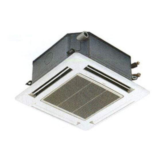
SPLIT-TYPE, HEAT PUMP AIR CONDITIONERS
TECHNICAL & SERVICE MANUAL
Indoor unit
[Model names]
PLH-3AAK
PLH-4AAK
PLH-5AAK
PLH-6AAK
PLH-3AAKH
PLH-4AAKH
PLH-5AAKH
PLH-6AAKH
Model name
indication
INDOOR UNIT
ON/OFF
TEMP
WIRELESS REMOTE
CONTROLLER
[Service Ref.]
PLH-3AAK
PLH-4AAK
PLH-5AAK
PLH-6AAK
PLH-3AAKH
PLH-4AAKH
PLH-5AAKH
PLH-6AAKH
TEMP.
ON/OFF
WIRED REMOTE
CONTROLLER
NOTE:
• This manual does not
CONTENTS
1. REFERENCE MANUAL ······································2
2. PART NAMES AND FUNCTIONS ···················3
3. SPECIFICATIONS ············································6
4. DATA ······························································14
5. OUTLINES AND DIMENSIONS ·····················28
6. WIRING DIAGRAM ········································31
7. REFRIGERANT SYSTEM DIAGRAM ············32
8. TROUBLESHOOTING ···································34
9. FUNCTION SETTING·····································50
10. 4-WAY AIR FLOW SYSTEM ··························57
11. SYSTEM CONTROL ······································62
12. DISASSEMBLY PROCEDURE ······················76
13. PARTS LIST ···················································79
14. OPTIONAL PARTS ········································84
February 2006
No. OC360
cover outdoor units.
When servicing outdoor
units, please refer to the
Outdoor Unit`s service
manual together with this
manual.
Advertisement
Table of Contents
Troubleshooting

Related Manuals for Mitsubishi PLH-3AAK


Summary of Contents for Mitsubishi PLH-3AAK
- Page 1 SPLIT-TYPE, HEAT PUMP AIR CONDITIONERS February 2006 No. OC360 TECHNICAL & SERVICE MANUAL Indoor unit [Model names] [Service Ref.] NOTE: • This manual does not PLH-3AAK PLH-3AAK cover outdoor units. When servicing outdoor PLH-4AAK units, please refer to the PLH-4AAK outdoor unit`s service PLH-5AAK...
-
Page 2: Reference Manual
REFERENCE MANUAL 1-1. OUTDOOR UNIT’S SERVICE MANUAL Service Ref. Service Manual No. PUH-3VKA .TH-A PUH-3YKA .TH-A OC156 PUH-4YKSA .TH-A PUH-5/6YKSA .TH-A PUH-3VKA.TH OC325 PUH-3YKA.TH PUH-4/5/6YKSA.TH PUH-3NKA.TH OC354 PUH-4/5/6TKSA.TH... -
Page 3: Part Names And Functions
PART NAMES AND FUNCTIONS Indoor Unit Filter Removes dust and pollutants from intake air Horizontal Air Outlet Sets airflow of horizontal automatically during cooling or dehumidifying. Grille Auto Air Swing Vane Disperses airflow up and down and adjusts the angle of airflow direction. - Page 4 Display “Sensor” indication Displayed when the remote controller sensor is used. Day-of-Week For purposes of this explanation, Shows the current day of the week. all parts of the display are shown as lit. During actual operation, only Time/Timer Display the relevant items will be lit. “Locked”...
-
Page 5: Wireless Remote Controller
Wireless remote controller display CHECK TEST RUN CHECK&TEST RUN display indicates that the unit is being checked or test-run. display MODEL SELECT Blinks when model is selected. display Lights up while transmission to the indoor unit is mode using switches. display SET TEMP. -
Page 6: Specifications
SPECIFICATIONS Service Ref. Item PLH-3AAK(H) Function Cooling Heating Btu/h 26,300 28,700[35,800] Capacity 7,700 8,400[10,500] Total input 3.32 3.11[5.21] Service Ref. PLH-3AAK(H) Power supply(phase, cycle,voltage) Single, 50Hz, 220-240V Input 0.17 0.17[2.27] Running current 0.81 0.81[9.47] Starting current 1.00 1.00[9.7] External finish Grille : Munsell 0.70Y 8.59/0.97... - Page 7 Service Ref. Item PLH-3AAK Cooling w1/w2 Heating w1 Function Btu/h 23,200/27,300 31,700 Capacity 6,800/8,000 9,300 Total input 4.29/3.68 3.49 Service Ref. PLH-3AAK Power supply(phase, cycle,voltage) Single, 60Hz, 220V Input 0.16 0.16 Running current 0.77 0.77 Starting current 1.00 1.00 External finish Grille : Munsell 0.70Y 8.59/0.97...
- Page 8 Service Ref. PLH-4AAK(H) Item Function Cooling Heating 33,100 35,500[44,400] Btu/h Capacity 9,700 10,400[13,000] Total input 3.46 3.45[6.05] Service Ref. PLH-4AAK(H) Power supply(phase, cycle,voltage) Single, 50Hz, 220-240V Input 0.26 0.26[2.86] Running current 1.25 1.25[11.93] Starting current 2.0[12.7] External finish Grille : Munsell 0.70Y 8.59/0.97 Heat exchanger Plate fin coil Fan(drive) x No.
- Page 9 Service Ref. PLH-4AAK Item Cooling w1/w2 Heating w1 Function Btu/h 33,800/37,400 41,300 Capacity 9,900/10,950 12,100 Total input 5.26/4.93 4.21 Service Ref. PLH-4AAK Power supply(phase, cycle,voltage) Single, 60Hz, 220V Input 0.25 0.25 Running current 1.19 1.19 Starting current External finish Grille : Munsell 0.70Y 8.59/0.97 Heat exchanger Plate fin coil Fan(drive) x No.
- Page 10 Service Ref. PLH-5AAK(H) Item Function Cooling Heating 42,300 47,800[58,000] Btu/h Capacity 12,400 14,000[17,000] Total input 4.51 4.46[7.46] Service Ref. PLH-5AAK(H) Power supply(phase, cycle,voltage) Single, 50Hz, 220-240V Input 0.30 0.30[3.30] Running current 1.43 1.43[13.77] Starting current 2.0[14.3] External finish Grille : Munsell 0.70Y 8.59/0.97 Heat exchanger Plate fin coil Fan(drive) x No.
- Page 11 Service Ref. PLH-5AAK Item Cooling w1/w2 Heating w1 Function Btu/h 37,500/44,400 56,300 Capacity 11,000/13,000 16,500 Total input 6.78/5.58 6.02 Service Ref. PLH-5AAK Power supply(phase, cycle,voltage) Single, 60Hz, 220V Input 0.26 0.26 Running current 1.24 1.24 Starting current External finish Grille : Munsell 0.70Y 8.59/0.97 Heat exchanger Plate fin coil Fan(drive) x No.
- Page 12 Service Ref. Item PLH-6AAK(H) Function Cooling Heating Btu/h 47,800 54,900[65,200] Capacity 14,000 16,100[19,100] Total input 5.07 4.92[7.92] Service Ref. PLH-6AAK(H) Power supply(phase, cycle,voltage) Single, 50Hz, 220-240V Input 0.34 0.34[3.34] Running current 1.64 1.64[13.94] Starting current 2.0[14.3] External finish Grille : Munsell 0.70Y 8.59/0.97 Heat exchanger Plate fin coil Fan(drive) x No.
- Page 13 Service Ref. Item PLH-6AAK Cooling w1/w2 Heating w1 Function 45,700/51,900 59,700 Btu/h Capacity 13,400/15,200 17,500 Total input 7.32/6.15 Service Ref. PLH-6AAK Power supply(phase, cycle,voltage) Single, 60Hz, 220V Input 0.28 0.28 Running current 1.34 1.34 Starting current External finish Grille : Munsell 0.70Y 8.59/0.97 Heat exchanger Plate fin coil Fan(drive) x No.
- Page 14 DATA 1. PERFORMANCE DATA [50Hz] 1) COOLING CAPACITY(1) PLH-3AAK(H) Outdoor intake air D.B.(°C) Indoor Indoor Intake air Intake air D.B.(°C) W.B.(°C) P.C. P.C. P.C. 7768 4972 0.64 2.66 7555 4835 0.64 2.77 7278 4658 0.64 2.99 0.52 0.52 8271 4301 2.71...
- Page 15 COOLING CAPACITY(2) PLH-3AAK(H) Outdoor intake air D.B.(°C) Indoor Indoor Intake air Intake air D.B.(°C) W.B.(°C) P.C. P.C. P.C. 6983 4469 0.64 3.20 6671 4269 0.64 3.42 6342 4059 0.64 3.64 7452 3875 0.52 3.28 7130 3708 0.52 3.51 6793 3532 0.52...
- Page 16 COOLING CAPACITY(3) PLH-4AAK(H) Outdoor intake air D.B.(°C) Indoor Indoor Intake air Intake air D.B.(°C) W.B.(°C) P.C. P.C. P.C. 9786 6752 0.69 2.77 9518 6567 0.69 2.89 9168 6326 0.69 3.11 10419 5939 0.57 2.83 10145 5783 0.57 2.95 0.57 9775 5572 3.18 9786...
- Page 17 COOLING CAPACITY(4) PLH-4AAK(H) Outdoor intake air D.B.(°C) Indoor Indoor Intake air Intake air D.B.(°C) W.B.(°C) P.C. P.C. P.C. 8797 6070 0.69 3.34 8404 5798 0.69 3.56 7989 5512 0.69 3.79 9388 5351 0.57 3.42 8982 5120 0.57 3.65 0.57 8558 4878 3.89 8797...
- Page 18 COOLING CAPACITY(5) PLH-5AAK(H) Outdoor intake air D.B.(°C) Indoor Indoor Intake air Intake air D.B.(°C) W.B.(°C) P.C. P.C. P.C. 12510 7881 0.63 3.61 12167 7665 0.63 3.77 11720 7384 0.63 4.06 13319 6793 0.51 3.69 12969 6614 0.51 3.85 12496 6373 0.51 4.15 12510...
- Page 19 COOLING CAPACITY(6) PLH-5AAK(H) Outdoor intake air D.B.(°C) Indoor Indoor Intake air Intake air D.B.(°C) W.B.(°C) P.C. P.C. P.C. 11245 7085 0.63 4.35 10743 6768 0.63 4.64 10212 6434 0.63 4.94 12001 6120 0.51 4.46 11482 5856 0.51 4.76 10939 5579 0.51 5.07 11245...
- Page 20 COOLING CAPACITY(7) PLH-6AAK(H) Outdoor intake air D.B.(°C) Indoor Indoor Intake air Intake air D.B.(°C) W.B.(°C) P.C. P.C. P.C. 14124 8616 0.61 4.06 13737 8380 0.61 4.24 13232 8072 0.61 4.56 15038 7369 0.49 4.15 14642 7175 0.49 4.32 14109 6913 0.49 4.67 14124...
- Page 21 COOLING CAPACITY(8) PLH-6AAK(H) Outdoor intake air D.B.(°C) Indoor Indoor Intake air Intake air D.B.(°C) W.B.(°C) P.C. P.C. P.C. 12696 7745 0.61 4.89 12129 7399 0.61 5.22 11530 7033 0.61 5.55 13549 6639 0.49 5.01 12963 6352 0.49 5.35 12351 6052 0.49 5.70 12696...
-
Page 22: Performance Curve
0.993 0.990 PLH-6AAK(H) 1.00 1.00 1.00 1.00 1.00 1.00 0.998 0.995 0.993 0.990 2. PERFORMANCE CURVE PLH-3AAK(H) / PLH-4AAK(H) / PLH-5AAK(H) / PLH-6AAK(H) Cooling Heating INDOOR WB(°C) INDOOR DB (°C) INDOOR WB(°C) INDOOR DB (°C) -12-10 OUTDOOR DB(°C) OUTDOOR WB(°C) - Page 23 3. PERFORMANCE DATA [60Hz] 1) COOLING CAPACITY(1) PLH-3AAK / PLH-4AAK / PLH-5AAK / PLH-6AAK Indoor Outdoor intake air D.B.(°C) Service Ref. intake air W.B.(°C) P.C. P.C. P.C. P.C. P.C. P.C. 8071 2.95 7850 3.08 7561 3.31 7255 3.55 6931 3.79 6589 4.03...
-
Page 24: Electrical Data
4. ELECTRICAL DATA 3SPECIFICATIONS regarding the combination of Refer to Indoor unit … 220V 50Hz 1phase PUH-3NKA or PUH-4/5/6TKSA. Outdoor unit … 220V 50Hz 1phase / 380V 50Hz 3phase Service Ref. PLH-3AAK(H) PLH-4AAK(H) PLH-5AAK(H) PLH-6AAK(H) Mode Cool Heat Cool Heat... -
Page 25: Standard Operation Data
5. STANDARD OPERATION DATA Service Ref. PLH-3AAK(H) PLH-4AAK(H) PLH-5AAK(H) PLH-6AAK(H) Mode Cooling Heating Cooling Heating Cooling Heating Cooling Heating Capacity 7,700 8,400 9,700 10,400 12,400 14,000 14,000 16,100 Input 3.32 3.11 3.46 3.45 4.51 4.46 5.07 4.92 Indoor unit Service Ref. -
Page 26: Noise Criterion Curves
7. NOISE CRITERION CURVES PLH-3AAK(H) PLH-4AAK(H) NOTCH SPL(dB) LINE NOTCH SPL(dB) LINE High High NC-70 NC-70 NC-60 NC-60 NC-50 NC-50 NC-40 NC-40 NC-30 NC-30 APPROTIMATE APPROTIMATE TERESHOLD OF TERESHOLD OF REARING FOR REARING FOR NC-20 NC-20 CONTINUOUS CONTINUOUS NOISE NOISE... - Page 27 UNIT Ambient temperature 27: CEILING Test conditions are based on JIS Z8731 1.5m MICROPHONE...
-
Page 28: Outlines And Dimensions
OUTLINES AND DIMENSIONS 1. INDOOR UNIT PLH-3AAK(H) Unit : mm PLH-4AAK(H) PLH-5AAK(H) PLH-6AAK(H) Ceiling hole 20~45 860~910 20~45 Branch duct hole Fresh air intake (Cut out hole) Suspension bolt pitch 90 100 100 90 Branch duct hole Branch duct hole Terminal block 14 - {2.8... - Page 29 Unit : mm WIRED REMOTE CONTROLLER...
- Page 30 Unit : mm WIRELESS REMOTE CONTROLLER...
-
Page 31: Wiring Diagram
WIRING DIAGRAM PLH-3AAK PLH-4AAK PLH-5AAK PLH-6AAK PLH-3AAKH PLH-4AAKH PLH-5AAKH PLH-6AAKH [LEGEND] SYMBOL NAME SYMBOL NAME SYMBOL NAME INDOOR POWER BOARD CAPACITOR(FAN MOTOR) WIRELESS REMOTE CONTROLLER BOARD INDOOR CONTROLLER BOARD FAN MOTOR RECEIVING UNIT FUSE FUSE(T6.3AL250V) VANE MOTOR BUZZER VARISTOR DEW PREVENTION HEATER... -
Page 32: Refrigerant System Diagram
REFRIGERANT SYSTEM DIAGRAM Unit : mm PLH-3AAK(H)/ PUH-3VKA.TH · PUH-3VKA .TH-A Refrigerant flow in cooling Refrigerant flow in heating PUH-3YKA.TH · PUH-3YKA .TH-A <R.V.coil> High pressure Heating ON control switch Oil separator Cooling OFF Refrigerant pipe Outdoor unit Service Ball valve... - Page 33 PLH-4AAK/PUH-4TKSA.TH Outdoor unit Oil separator High pressure Refrigerant pipe Outdoor heat exchanger control switch Ball valve (option) 4-way valve Indoor unit 19.05 ( [3/4") Service (with heat insulator) Strainer port Flexible tube Thermistor Indoor Service heat port Bypass exchanger Restrictor valve Flared valve...
- Page 34 TROUBLESHOOTING 8-1. TROUBLESHOOTING <Error code display by self-diagnosis and actions to be taken for service (summary)> Present and past error codes are logged and displayed on the wired remote controller or controller board of outdoor unit. Actions to be taken for service,which depends on whether or not the the inferior phenomenon is reoccurring at service, are summarized in the table below.
- Page 35 < Malfunction-diagnosis method at maintenance service> Wireless remote controller [Procedure] 1. Press the CHECK button twice. • "CHECK" lights, and address "00" flash- Address display • Check that the remote controller's CHECK display has stopped before continuing. CHECK display 2. Press the temperature •...
- Page 36 • If the unit cannot be operated properly after the above test run has been performed, refer to the following table to remove the cause. Symptom Cause Wired remote controller For about 2 •For about 2 minutes following power-on,op- PLEASE WAIT minutes follow- eration of the remote controller is not possible ing power-on...
- Page 37 Note: Refer to the manual of outdoor unit for the details of display 8-3. SELF-DIAGNOSIS ACTION TABLE such as F, U, and other E. Error Code Meaning of error code and detection method Countermeasure Cause Abnormality of room temperature 1 Defective thermistor 1–3 Check resistance value of thermistor.
- Page 38 Error Code Meaning of error code and detection method Countermeasure Cause Freezing/overheating protection is (Cooling or drying mode) (Cooling or drying mode) working 1 Clogged filter (reduced airflow) 1 Check clogs of the filter. 1 Freezing protection (Cooling mode) 2 Short cycle of air path 2 Remove shields.
- Page 39 Error Code Meaning of error code and detection method Countermeasure Cause Remote controller transmission 1 Contact failure at transmission 1 Check disconnection or looseness of indoor error(E0)/signal receiving error(E4) wire of remote controller unit or transmission wire of remote controller. 2 Set one of the remote controllers “main”.
- Page 40 Error Code Meaning of error code and detection method Countermeasure Cause 1 Defective indoor controller 1 Replace indoor controller board. Abnormality of indoor controller board Abnormal if data cannot be normally read board. from the nonvolatile memory of the indoor controller board.
- Page 41 8-4. TROUBLESHOOTING BY INFERIOR PHENOMENA Phenomena Cause Countermeasure (1)LED2 on indoor controller board • When LED1 on indoor controller board is also off. 1 Power supply of 220~240V AC is not supplied to 1 Check the voltage of indoor power supply is off.
-
Page 42: Before Test Run
Phenomena Cause Countermeasure (3)Upward/downward vane 1 The vane is not downward during defrosting and 1 Normal operation (The vane is set to hor- heat preparation and when the thermostat is OFF in izontal regardless of remote control.) performance failure HEAT mode. (Working of COOL protection function) 2 Vane motor does not rotate. - Page 43 8-5-3. Test run (Using wireless remote controller) 1 Turn on the power to the unit at least 12 hours before the test run. TEST RUN 2 Press the button twice continuously. (Start this operation from the status of remote controller display turned off.) TEST RUN and current operation mode are displayed.
- Page 44 8-6. HOW TO CHECK THE PARTS PLH-3AAK PLH-4AAK PLH-5AAK PLH-6AAK PLH-3AAKH PLH-4AAKH PLH-5AAKH PLH-6AAKH Parts name Check points Room temperature Disconnect the connector then measure the resistance using a tester. thermistor (TH1) (Surrounding temperature 10:~30:) Pipe temperature Normal Abnormal thermistor/liquid(TH2) (Refer to the thermistor) 4.3k"~9.6k"...
- Page 45 <Thermistor Characteristic graph> Room temperature thermistor(TH1) Thermistor for < Thermistor for lower temperature > Pipe temperature thermistor/liquid(TH2) lower temperature Thermistor R =15k' ± 3% Fixed number of B=3480 ± 2% Rt=15exp { 3480( 273+t 15k' 9.6k' 6.3k' 5.4k' 4.3k' 3.0k' -20 -10 0 10 20 30 40 50 Temperature (:)
- Page 46 8-7.TEST POINT DIAGRAM 8-7-1. Power board PLH-3AAK(H) PLH-4AAK(H) PLH-5AAK(H) PLH-6AAK(H) CN2S Connect to the indoor controller board (CN2D) Between 1 1 to 3 3 12.6-13.7V DC (Pin1 1 (+)) CNSK Connect to the indoor controller board (CNDK) 1 1 to 3 3 220-240V AC...
- Page 47 8-7-2. Indoor controller board PLH-3AAK(H) PLH-4AAK(H) PLH-5AAK(H) PLH-6AAK(H) CN2D LED1 LED2 Connect to the indoor Power supply (I.B) Power supply (R.B) power board (CN2S) (12.5~13.7V DC) CN22 Connect to the terminal block(TB5) (Remote controller connecting wire) (10.4~14.6V DC) CN30 Transmission...
- Page 48 Remarks MODELS 1 2 3 4 5 Model PLH-AAK settings 1 2 3 4 5 PLH-AAKH MODELS 1 2 3 4 5 PLH-3AAK PLH-3AAKH 1 2 3 4 5 PLH-4AAK PLH-4AAKH Capacity settings 1 2 3 4 5 PLH-5AAK PLH-5AAKH...
- Page 49 8-9 OUTDOOR UNIT SERVICE FUNCTIONS (OUTDOOR CONTROLLER BOARD) (1) Compulsory defrosting 1When all of the following conditions are satisfied, pressing SW2 starts the compulsory defrosting. During HEAT mode The compressor is ON. The outdoor coil temperature is being displayed by LED. (Outdoor controller board dip switch SW3-1 : OFF, SW3-2 : The outdoor coil thermistor reads 8°C or below.
-
Page 50: Function Setting
FUNCTION SETTING 9-1. UNIT FUNCTION SETTING BY THE REMOTE CONTROLLER Each function can be set according to necessity using the remote controller. The setting of function for each unit can only be done by the remote controller. Select function available from the table 1. <Table 1>... - Page 51 Rotation setting ( Function setting mode No.20 ) Function setting Features Indoor controller board Mode No. SW5-3 setting SW5-4 setting Setting No. Each system operates alternately for ( 24hours 24hours. cycle ) Each system operates alternately for OFF : Main ( 168hours 168hours.
- Page 52 Selecting functions using the wired remote controller 1 Check the function selection setting. 2 Switch to function setting mode. For modes 15 and higher, (Press A and B at the same time press J and B at the same time. with the remote controller stopped.) 3 Specify address 4 Specify unit No.
- Page 53 [Operating Procedure] 1 Check the setting items provided by function selection. If settings for a mode are changed by function selection, the functions of that mode will be changed accordingly. Check all the current settings according to steps 2 to 7 , fill in the "Check" column in Table 1, and then change them as necessary. For factory settings, refer to the indoor unit's installation manual. 2 Switch off the remote controller.
- Page 54 9-1-2. Selecting functions using the wireless remote controller (Type C) Functions can be selected with the wireless remote controller. Function selection using wireless remote controller is available only for refriger- ant system with wireless function. Address cannot be specified by the wireless remote controller. [Flow of function selection procedure] The flow of the function selection procedure is shown below.
- Page 55 9-2. FUNCTION SELECTION OF REMOTE CONTROLLER The setting of the following remote controller functions can be changed using the remote controller function selection mode. Change the setting when needed. Item 1 Item 2 Item 3 (Setting content) 1.Change Language Language setting to display •...
- Page 56 Flowchart of Function Setting Setting language (English) Normal display (Display when the air condition is not running) Hold down the button and press the button for 2 seconds. Hold down the button and press the button for 2 seconds. Press the operation mode button. Press the TIMER MENU button.
-
Page 57: Way Air Flow System
2) According to the number of air outlets and height of the ceiling to install the unit, be sure to set the unit function setting by the remote controller. Correspondence of ceiling heights to numbers of air outlets. Ceiling height & discharge direction (Unit : m) High ceiling 1 High ceiling 2 PLH-3AAK(H) Standard 4 direction 2.7m 3.0m 3.5m 3 direction 3.3m... - Page 58 3. Fresh air intake amount & static pressure characteristics l l PLH-3AAK(H) Multifunction casement + Standard filter Multifunction casement + High efficiency filter Static pressure [Pa] Static pressure [Pa] Air flow [m /min] Air flow [m /min] 2 intakes 2 intakes...
- Page 59 4. Interlocking operation method with duct fan (Booster fan) Whenever the indoor unit is operating, the duct fan also Be sure to secure insulation operates. material by tape and such (1)Connect the optional multiple remote controller Green CN51 adapter(PAC-SA88HA-E)to the connector CN51 on the Yellow indoor indoor controller board.
- Page 60 6. Air flow & Static pressure characteristics of Branch Duct (Air flow( Fan speed) at “Standard”) 4 direction airflow (Horizontal vane) Rounded duct Angled duct PLH-3AAK(H) PLH-3AAK(H) Static Static pressure pressure [Pa] [Pa] Air flow [m /min] Air flow [m...
- Page 61 2 direction airflow (Horizontal vane) Rounded duct Angled duct PLH-3AAK(H) PLH-3AAK(H) Static Static pressure pressure [Pa] [Pa] 1 2 3 4 5 6 7 8 9 10 11 1 2 3 4 5 6 7 Air flow [m /min] Air flow [m...
-
Page 62: System Control
SYSTEM CONTROL 11-1. VARIETY OF SYSTEM CONTROL FUNCTIONS Parts Required in Addition to Standard System System Name System Diagram Features Components (Indoor/Outdoor Units, Remote Controller) • There are two types of remote controllers: wired type Indoor unit and wireless type. A.Remote control- •... - Page 63 (Only the microcomputer type Lossnay ventilator Enables control of Remote can be used.) Mitsubishi Lossnay Controller ventilator by remote controller. • When abnormality occurs while operating, it changes This system can correspond only by...
- Page 64 11-2. ONE REMOTE CONTROLLER (STANDARD) OPERATION (1) One Wired Remote Controller (OC: Outdoor unit IC: Indoor unit R: Remote controller (for wireless type: optical receiver adapter) Slim Air Conditioners System Standard 1:1 Simultaneous Twin Indoor controller board switch setting Outdoor unit Remote controller SW5-3 Indoor unit IC...
- Page 65 11-3. TWO-REMOTE CONTROLLER OPERATION (1) Two Wired Remote Controllers Indoor controller board switch setting (R: Wired remote controller) Slim Air Conditioner System Standard 1:1 Simultaneous Twin SW5-3 Indoor unit IC Outdoor unit Indoor/outdoor IC-1 (Main) connection cable Indoor unit IC IC-1 IC-2 Remote...
-
Page 66: Group Control Operation
11-4. GROUP CONTROL OPERATION (COLLECTIVE OPERATION AND CONTROL OF MULTIPLE REFRIGERANT SYSTEMS (2 to 16)) Group control can be operated by using MAC-397IF-E. The setting of wired remote controller is subjected to variation according to the function of the indoor unit. (for mode operation, setting temperature, fan step, air direction) The display of remote controller and operating the indoor unit might be different. - Page 67 Use as a Wired Remote Control (Using the MA Remote Controller) Note: 1. Be sure the Auto Heating/Cooling Display Setting on the MA remote controller is set to OFF before use. • For information on how to set the Auto/Heating Cooling Display Setting, see the MA remote controller instruction manual.
- Page 68 SW501: Settings to accommodate MA remote controller and settings to accommodate outdoor units SW No. Functions Comments No. 1 Only specify these settings when connecting an MA remote controller. Refrigerant address 0 No. 2 No. 3 No. 4 Refrigerant address 1 Refrigerant address 2 Refrigerant address 3 Refrigerant address 4...
- Page 69 SW502 : Air Conditioner Function Settings SW No. Functions Comments No. 1 Cooling only type/ Heat pump type Heat pump type Cooling only type Set the mode in accordance with the operation manual for the indoor unit. Not available Available Heat pump type : Set to ON.
- Page 70 When Mounting Directly to a Wall Mount the interface unit case to the wall using the mounting When mounting the interface unit inside a ceiling or wall, install an access door to facilitate mainte- screws. nance. Interface case When the interface unit is mounted mounting screws above an indoor unit, it should be positioned 40 mm or more away from the...
- Page 71 11-5. POWER OUTAGE AUTOMATIC RECOVERY OPERATION • Whenever a power outage or switching of the power supply causes the power supply of an operating air conditioner to go from OFF to ON, this function will automatically restore the operation of the air conditioner to its previous operating mode. w If the power is turned from OFF to ON when the air conditioner is not in operation, the air conditioner will not automatically be turned on.
- Page 72 (2). Basic wiring diagram (3). Part specifications No.1 unit No.2 unit Remote/Hand-held 1 Remote/Hand-held 2 Adapter for 3 Relay box relay box relay box selection switch selection switch remote start/stop Control circuit (Example) Model T Timer power supply next Single polarity PAC-SE55RA-E (On delay system) unit...
-
Page 73: Timer Operation
11-8. OBTAINING REMOTE DISPLAY Use the A control operating display kit (PAC-SF40RM-E) to provide operation/error non-voltage contact output and on/off input function. (1). Wiring method External input External input No voltage (Momentary "a" contact) Wireless CN90 Error output Error (No voltage momentary "a" contact) Operating output Operation (No voltage momentary "a"... - Page 74 Humidifier Relay box unit X: Relay (On-site tinstallation) (DC12V) CN25 (Indoor unit circuit board) W Please consult your nearest Mitsubishi Electric Indoor unit representative for information about obtaining the adapter for humidifier signal. Remote controller Remote controller 11-12. EXTERNAL MOUNTING OF TEMPERATURE SENSOR Temperature control from an alternative external location can be performed by connecting the temperature sensor (Model PAC-SE41TS-E - sold separately) to the CN20 connector on the circuit board for the indoor unit.
- Page 75 Indoor controller board 11-13. MULTIPLE REMOTE CONTROL DISPLAY You can control several units with a multiple remote control display, by Indoor controller board wiring an optional multiple display adapter (PAC-SA88HA-E) with relays and lamps on the market. How to wire (1) Connect the multiple display adapter to the connector CN51 on the indoor controller board.
-
Page 76: Disassembly Procedure
DISASSEMBLY PROCEDURE PLH-3AAKH Be careful on removing heavy parts. OPERATING PROCEDURE PHOTOS&ILLUSTRATIONS 1. Removing the air intake grille Figure 1 (1) Slide the knob of air intake grille to the direction of the arrow 1 to open the air intake grille. Air intake grille (2) Remove the string hook from the panel to pretend the grille from dropping. - Page 77 OPERATING PROCEDURE PHOTOS&ILLUSTRATIONS 4. Remove the fan motor Photo 3 (1) Remove the bell mouth.(See photo 1) Fan motor (2) Remove the electrical box.(See photo 2) (3) Remove the turbo fan nut. (4) Pull out the turbo fan. (5) Disconnect the connector of the fan motor lead wire. (6) Remove the 4 nuts of the fan motor.
- Page 78 OPERATING PROCEDURE PHOTOS&ILLUSTRATIONS 8. Removing the drain pump and drain sensor Photo 8 (1) Remove the panel. (See photo 5) (2) Remove the bell mouth. (See photo 1) (3) Remove the electrical box. (See photo 2) (4) Remove the drain pan. (See photo 6) (5) Remove the 3 screws of the drain pump.
-
Page 79: Parts List
PARTS LIST PANEL PARTS PLP-6AA PLP-6AAL GEAR GEAR (VANE) VANE BUSH VANE MOTOR RECEIVER CHECK TEST RUN MODEL SELECT ˚C AMPM AMPM NOT AVAILABLE CENTRALLY CONTROLLED 1Hr. ON/OFF TEMP ON OFF ˚C CHECK CLOCK FILTER CHECK MODE ˚C TEST RUN STAND BY ERROR CODE NOT AVAILABLE... - Page 80 FUNCTIONAL AND STRUCTURE PARTS PLH-3AAK PLH-4AAK PLH-5AAK PLH-6AAK SPL WASHER PIPE TEMPERATURE THERMISTOR RESTRICTOR VALVE Q'ty / set Price Wiring Recom- Remarks PLH-AAK Parts No. Specification Parts Name Diagram mended (Drawing No.) Symbol Q'ty Unit Amount — (RG00G462G34) BASE —...
- Page 81 FUNCTIONAL AND STRUCTURE PARTS PLH-3AAKH PLH-4AAKH PLH-5AAKH PLH-6AAKH SPL WASHER THERMAL FUSE HEATER THERMAL SWITCH PIPE TEMPERATURE THERMISTOR RESTRICTOR VALVE Q'ty / set Price Wiring Recom- Remarks Specification Parts No. Parts Name PLH -AAKH Diagram mended (Drawing No.) Amount Unit Symbol Q'ty —...
- Page 82 FUNCTIONAL AND STRUCTURE PARTS PLH-3AAK PLH-4AAK PLH-5AAK PLH-6AAK DRAIN PLUG DRAIN PLUG CAPACITOR TERMINAL BLOCK TERMINAL BLOCK FUSE TERMINAL BLOCK ROOM TEMPERATURE THERMISTOR Q'ty / set Price Wiring Recom- Remarks PLH-AAK Parts No. Specification Parts Name Diagram mended (Drawing No.)
- Page 83 FUNCTIONAL AND STRUCTURE PARTS PLH-3AAKH PLH-4AAKH PLH-5AAKH PLH-6AAKH DRAIN PLUG DRAIN PLUG CAPACITOR RELAY TERMINAL BLOCK TERMINAL BLOCK TERMINAL BLOCK ROOM TEMPERATURE THERMISTOR Q'ty / set Price Wiring Recom- Remarks Specification PLH -AAKH Parts No. Parts Name Diagram mended (Drawing No.) Amount Unit Symbol...
-
Page 84: Optional Parts
OPTIONAL PARTS 1. REFRIGERANT PIPES Service Ref. : PLH-3AAK(H) Part No. PAC-05FFS-E PAC-07FFS-E PAC-10FFS-E PAC-15FFS-E Pipe length Pipe size O.D . Liquid:[9.52 Gas:[15.88 Connection method Indoor unit: Flared Outdoor unit: Flared Service Ref. : PLH-4AAK(H), PLH-5AAK(H), PLH-6AAK(H) Part No. PAC-PC51PI-E... - Page 85 6. MULTI FUNCTION CASEMENT (For HIGH EFFICIENCY FILTER AND FRESH AIR INTAKE) Part No. PAC-SG03TM-E Applicable Service Ref. PLH-3/4/5/6AAK(H) (PAC-SG03TM-E is needed) 7. HIGH EFFICIENCY FILTER ELEMENT PAC-SG01KF Part No. PLH-3/4/5/6AAK(H) Applicable Service Ref. 8. AIR OUTLET SHUTTER PLATE (20set, 2pcs/set) Part No.
- Page 86 HEAD OFFICE : TOKYO BLDG., 2-7-3, MARUNOUCHI, CHIYODA-KU TOKYO 100-8310, JAPAN © Copyright 2006 MITSUBISHI ELECTRIC ENGINEERING CO.,LTD. Distributed in Feb. 2006 No.OC360 PDF 9 New publication, effective Feb. 2006 Made in Japan Specifications subject to change without notice...
Need help?
Do you have a question about the PLH-3AAK and is the answer not in the manual?
Questions and answers