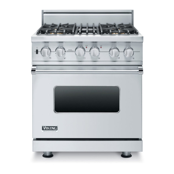
Viking VGSC530 Service Manual
30, 36, & 48 inch self-clean gas ranges
Hide thumbs
Also See for VGSC530:
- Manual (48 pages) ,
- Installation manual (30 pages) ,
- Installation instructions manual (12 pages)
Table of Contents
Advertisement
Quick Links
Service
Manual
This manual is to be used by qualifi ed appliance technicians only. Viking
does not assume any responsibility for property damage or personal
injury for improper service procedures done by an unqualifi ed person.
30, 36, & 48 Inch
Self-Clean
Gas Ranges
Preferred Service
This Base Manual covers general and
specifi c information including, but not
limited to the following models:
®
VGSC530
VGSC536
VGSC548
SMC-0010
April 2010
Advertisement
Table of Contents

Related Manuals for Viking VGSC530


Summary of Contents for Viking VGSC530
- Page 1 Service Preferred Service Manual This manual is to be used by qualifi ed appliance technicians only. Viking does not assume any responsibility for property damage or personal injury for improper service procedures done by an unqualifi ed person. 30, 36, & 48 Inch This Base Manual covers general and specifi...
-
Page 2: Important Information
All safety messages will be preceded by the safety alert symbol and the word “DANGER”, “WARNING”, or “CAUTION”. These words mean: VIKING will not be responsible for any injury or property damage from improper service procedures. If performing service on your own product, you must... - Page 3 Freestanding gas ranges and all of their component parts, except as detailed below*, are warranted to be free from defective materials or workmanship in normal household use for a period of twelve (12) months from the date of original retail purchase. Viking Range Corporation, warrantor, agrees to repair or replace, at its option, any part which fails or is found to be defective during the warranty period.
-
Page 4: Table Of Contents
Bake Operation ........... 18 Cooling Fan Removal (VGSC536 Only) ....38 Checking Oven Broil Operation ......19 Cooling Fan Removal (VGSC530 and VGSC548) . 38 Checking 48" LH Oven Operation....... 20 Gas Solenoid Valve Removal......... 39 Checking Griddle Operation ....... 21 Pressure Regulator Removal ......... -
Page 5: General Information
8 ” 26-7/16” (67.2 cm) - 7 / ( 7 5 8 ” 8-1/8” 1” (20.6 cm) (2.5 cm) 35-7/8” (91.1 cm) min. 37” (94 cm) max. 19-3/8” (49.2 cm) 25-3/4” (65.4 cm) 45-1/8” (114.6 cm) ©2010 Viking Preferred Service... -
Page 6: Specifi Cations
• Wall cabinets directly above product must be a minimum of 42" (106.7 cm) above cooking surface • Rear - 0" with 8" backguard or high shelf; 0" with island trim and non-combustible rear wall • 6" (15.2 cm) with island trim and combustible rear wall ©2010 Viking Preferred Service... -
Page 7: Warnings
To Prevent Fire or Smoke Damage such as the oven vent opening, the surface near the • Be sure all packing materials are removed from the vent opening, and the oven door window. appliance before operating it. ©2010 Viking Preferred Service... -
Page 8: Cleaning Safety
After oven is turned off, DO NOT touch the oven vent or surrounding areas until they have had suffi cient time to cool. ©2010 Viking Preferred Service... -
Page 9: Electrical & Gas Requirements
DO NOT USE AN OPEN FLAME TO CHECK FOR GAS LEAKS. Connect gas and electric. Before placing appliance in operation, always check for gas leaks. This must be performed by your dealer, a qualifi ed licensed plumber, or gas service company. ©2010 Viking Preferred Service... -
Page 10: Performance Checklist
• Four lights illuminate the oven cavity with less glare. • Six rack positions and three racks provide ample space for your baking needs. • This appliance is certifi ed by Star-K to meet strict regulations in conjunction with specifi c instructions found on www.star-k.org. ©2010 Viking Preferred Service... -
Page 11: Range Features
2. Island trim 48” Six-Burner/Grill 48” Four-Burner/Grill/Griddle 3. Grill (Optional) 4. Griddle (Optional) 5. Identifi cation plate (or located under base) 6. Three standard heavy-duty tilt-proof racks. Six rack positions 7. Broiler pan–located inside oven ©2010 Viking Preferred Service... -
Page 12: Troubleshooting
2 fl ashes, then 4 seconds OFF (Oven Probe) Model Header 3 fl ashes, then 4 seconds OFF Thermostat Control Connections This controller is used for the 48" left oven and for the griddle. (Part may vary) ©2010 Viking Preferred Service... -
Page 13: Fault Codes For Dsi Boards
Gas solenoid fault. Check wiring and gas solenoid. 7 fl ashes every 4 seconds Power up with channel on. Switch channel off and retry. 8 fl ashes every 4 seconds Gas solenoid fault. Check wiring and gas solenoid. Direct Spark Module Connections ©2010 Viking Preferred Service... -
Page 14: Led Error Codes
1 second ON, 1 second OFF (Oven Probe) Model 2 fl ashes, then 4 seconds OFF A/D Stuck 3 fl ashes, then 4 seconds OFF Fan Hall 4 fl ashes, then 4 seconds OFF Self-Cleaning Oven Control Board Connections ©2010 Viking Preferred Service... -
Page 15: Oven Components - Rh Oven
Defective cycle or clean light Replace light oven, LH oven, surface burner, grill, and (neon) griddle igniters operate Open oven control board Replace oven control board Defective oven wiring (shorted, Repair or replace defective wiring open, or burned) ©2010 Viking Preferred Service... -
Page 16: Oven Components - Lh Oven
Oven cycle light inoperable - RH Defective cycle light (neon) Replace cycle light oven, LH oven, surface burner, grill, and griddle igniters operate Open thermostat Replace thermostat Defective oven wiring (shorted, Repair or replace defective wiring open, or burned) ©2010 Viking Preferred Service... -
Page 17: Surface Burners, Grill, And Griddle
Griddle cycle light inoperable - RH Defective cycle light (neon) Replace cycle light oven, LH oven, surface burner, grill, Open griddle control Replace griddle control and griddle igniters operate Defective oven wiring (shorted, Repair or replace defective wiring open, or burned) ©2010 Viking Preferred Service... -
Page 18: Checking 30", 36", Or 48" Rh Oven Bake Operation
SC to S1 while 210 present S1 brown to SC black\white? arcing, yet no gas present to bake burner? (Gas supply valve in open position) Replace bake solenoid valve. Repair or replace defective wiring. ©2010 Viking Preferred Service... -
Page 19: Checking Oven Broil Operation
SC to S2 while 210 present S2 yellow to SC black\white? arcing, yet no gas present to broil burner? (Gas supply valve in open position) Replace broil solenoid valve. Repair or replace defective wiring. ©2010 Viking Preferred Service... -
Page 20: Checking 48" Lh Oven Operation
(Gas supply valve in open position) Disconnect power to range. Replace bake solenoid Check bake solenoid resistance. valve. 210 present S1 brown to SC black\white? ©2010 Viking Preferred Service... -
Page 21: Checking Griddle Operation
Disconnect power to range. Check griddle solenoid resistance. Replace griddle 210 present S1 yellow (48" Series) to SC black\white? solenoid valve. 210 present S1 orange (36" Series) to SC black\white? ©2010 Viking Preferred Service... -
Page 22: Selector And Thermostat Characteristics
6.06 k Broil 8.79 k 1.91 k 6.95 k 680 Clean 8.79 k 8.20 k Resistance checks are made on the thermostat wire harness with the thermostat wire harness disconnected from the board at location P14. ©2010 Viking Preferred Service... -
Page 23: Component Characteristics
Oven Light Switch - 0 VAC Oven light switch terminals - black to red Light Switch Closed Single Point Spark 120 VAC Not Applicable Single Point Spark Module - black to white Module *Resistance checks made with power off. ©2010 Viking Preferred Service... -
Page 24: Spark Module Test
RTD. If the RTD test resistance is within specifi cations and the consumer is having erratic oven temperatures, please call Viking 7. Remove the grate, burner cap, and burner head. Technical support (1-800-914-4799) for assistance. -
Page 25: Disassembly
Note: If the door needs to be adjusted, loosen hinge trim screws. Adjust the screws located between the door and kick plate using a " hex head allen wrench. Tighten hinge trim screws after adjustment is made. ©2010 Viking Preferred Service... -
Page 26: Door Handle Removal
4. Reverse procedure for installation. 2. Reverse procedure for installation. Door Logo Removal Condition Requirements: Outer Door Panel Assembly Removed 1. Remove two pal nuts and logo from outer door panel. 2. Reverse procedure for installation. ©2010 Viking Preferred Service... -
Page 27: Outer Door Glass Removal
Note: Use care with insulation; make sure to replace Note: The outer door glass is secured with double- any damaged or missing insulation. sided tape. Use care when removing from window holder. 3. Remove screws and inner door panel from inner door glass assembly. ©2010 Viking Preferred Service... -
Page 28: Left Oven Bake Burner And Igniter Removal (Vgsc548 Series)
4. Remove screw and igniter from burner. 1. Loosen two screws that secure bake burner in rear of cavity. 2. Remove two screws and bake burner from range. 5. Reverse procedure for installation. 3. Reverse procedure for installation. ©2010 Viking Preferred Service... -
Page 29: Bake Burner Orifi Ce Removal
3. Mark and disconnect two connectors from convection motor assembly. 4. Remove left hand nut and fan blade from convection fan. (View of top of oven cavity) 3. Reverse procedure for installation. 5. Reverse procedure for installation. ©2010 Viking Preferred Service... -
Page 30: Control Components Accessed
7. Remove grommets from control panel assembly. 7. Place control panel assembly on protective surface 8. Remove screws and false drip tray handle from on the top of range. control panel assembly. 9. Reverse procedure for installation. 8. Reverse procedure for installation. ©2010 Viking Preferred Service... -
Page 31: 48" Lh Oven/Griddle Control Removal
Control Components Accessed 30", 36" and 48" RH Oven Function 1. Remove screws and slide component tray forward. Selector Removal Note: VGSC530 shown. Other component tray Condition Requirements: configurations may be different on other models. Control Components Accessed 2. Mark and disconnect wires from door latch assembly. -
Page 32: Control Board Removal
Control Components Accessed 1. Remove screws and slide component tray forward. 1. Remove screws and slide component tray forward. Note: VGSC530 shown. Other component tray Note: VGSC530 shown. Other component tray configurations may be different on other models. configurations may be different on other models. -
Page 33: Oven Light Bulb Removal
3. Reverse procedure for installation. Control Components Accessed 1. Mark and disconnect two connectors from light switch. 2. Press tabs on both ends of the switch and push switch through control panel. 3. Reverse procedure for installation. ©2010 Viking Preferred Service... -
Page 34: Orifi Ce Removal
2. Pull to remove spark module from burner valve. 3. Remove fl ex tubing from back of burner valve. 4. Remove screw and burner valve from manifold assembly. 4. Reverse procedure for installation. 5. Reverse procedure for installation. 6. Perform gas leak test. ©2010 Viking Preferred Service... -
Page 35: Bake/Broil Gas Shutoff Valve Removal
2. Pull to remove spark module from burner valve. 3. Remove tubing from back of shutoff valve. 4. Remove screw and shutoff valve from manifold assembly. 4. Reverse procedure for installation. 5. Reverse procedure for installation. 6. Perform gas leak test. ©2010 Viking Preferred Service... -
Page 36: Griddle Temperature Sensor (Rtd) Removal (Vgsc536-4G, Vgsc548-6G, & Vgsc548-4Gq)
3. Reverse procedure for installation. Griddle Burner Igniter Removal (VGSC536-4G, VGSC548-6G, & VGSC548-4GQ) Condition Requirements: Griddle Plate and Drip Pan Removed 1. Remove two screws and igniter from range. 2. Disconnect wire from igniter. 3. Reverse procedure for installation. ©2010 Viking Preferred Service... -
Page 37: Main Top Removal
2. Remove fl ex tubing from jet holder. 3. Remove two screws and jet holder from top support. 5. Remove two screws and side trim from each side of range. 4. Reverse procedure for installation. 5. Perform gas leak test. ©2010 Viking Preferred Service... -
Page 38: Cooling Fan Removal (Vgsc536 Only)
Discharge capacitor through a resistor before attempting to service. Ensure all ground wires are connected before certifying unit as repaired and/or operational. Cooling Fan Removal Cooling Fan Removal (VGSC536 Only) (VGSC530 and VGSC548) Condition Requirements: Condition Requirements: Main Top Removed Main Top Removed 1. -
Page 39: Gas Solenoid Valve Removal
4. Remove two screws and solenoid valve from range. 3. Reverse procedure for installation. Note: Use approved sealant when installing pressure regulator. 4. Perform gas leak test. 5. Reverse procedure for installation. 6. Perform gas leak test. ©2010 Viking Preferred Service... -
Page 40: Side Trim And Side Panel Removal
4. Remove four screws and side panel from range. 3. Pull back insulation to access hinge receiver. 4. Remove two screws, hinge trim and hinge receiver from range. 5. Reverse procedure for installation. 5. Reverse procedure for installation. ©2010 Viking Preferred Service... -
Page 41: Back Panel Removal
(VGSC548 Left Oven) Island Trim or Backguard Assembly Removed Condition Requirements: Door Assembly Removed Note: VGSC530 shown. Other models will have 1. Remove two screws that attach the sensor to the different back panels. back of the oven liner. 1. Remove screws and back panel from range. -
Page 42: Temperature Sensor (Rtd) Removal
Back Panel Removed Back Panel Removed Note: The RTD on the VGSC536 has a connector Note: The RTD on the VGSC530 and VGSC548 right between the sensor and the oven control. oven does not have a connector between the 1. Find the RTD connector in the burner box area and sensor and the oven control. -
Page 43: Gas Tubing For Bake Burner Removal
3. Remove nut from broil burner and gas tubing from range. range. 4. Remove nut and bracket from gas tubing. 4. Reverse procedure for installation. 5. Reverse procedure for installation. 5. Perform gas leak test. 6. Perform gas leak test. ©2010 Viking Preferred Service... -
Page 44: Broil Burner Removal
3. Remove fi ve screws and rear broil burner bracket from oven cavity. 4. Remove four screws and front broil burner bracket from oven cavity. 5. Pull broil burner from range. 6. Reverse procedure for installation. ©2010 Viking Preferred Service... -
Page 45: Wiring Diagrams
Wiring Diagrams Electronic Thermostat - DSI System Griddle Control Thermostat and DSI Module System (VGSC536-4G) Oven and Griddle Control Thermostat and DSI Module System (VGSC548-4GQ/6G LH Oven) ©2010 Viking Preferred Service... - Page 46 Wiring Diagrams Oven Control Thermostat and DSI Module System (VGSC548-8B/6Q LH Oven) ©2010 Viking Preferred Service...
-
Page 47: Wiring Diagrams
Wiring Diagrams Wiring Diagrams VGSC530 Gas Self-Clean Range ©2010 Viking Preferred Service... - Page 48 Wiring Diagrams VGSC536-4G Gas Self-Clean Range ©2010 Viking Preferred Service...
- Page 49 Wiring Diagrams VGSC536-6B/4Q Gas Self-Clean Range ©2010 Viking Preferred Service...
- Page 50 Wiring Diagrams VGSC548-4GQ/6G Gas Self-Clean Range ©2010 Viking Preferred Service...
- Page 51 Wiring Diagrams VGSC548-6Q/8B Gas Self-Clean Range ©2010 Viking Preferred Service...
- Page 52 ©2010 Viking Preferred Service...
Need help?
Do you have a question about the VGSC530 and is the answer not in the manual?
Questions and answers