Table of Contents
Advertisement
Quick Links
Advertisement
Table of Contents

Subscribe to Our Youtube Channel
Related Manuals for NF WF1973

Summary of Contents for NF WF1973
- Page 1 MULTIFUNCTION GENERATOR WF1973/WF1974 Instruction Manual (Basics) NF Corporation...
- Page 2 DA00016809-001 MULTIFUNCTION GENERATOR WF1973/WF1974 Instruction Manual (Basics)
- Page 3 If reading this manual for the first time, start from 1. OVERVIEW of the Basics Instruction Manual. Basics 1. OVERVIEW Briefly describes and explains the features and brief operation principles of the WF1973/ WF1974. 2. PREPARATIONS BEFORE USE Describes various cautions regarding preparations to be made before using the WF1973/ WF1974, ranging from installation to connection of the power supply.
- Page 4 3. HANDY USE OF 2-CHANNEL DEVICE (WF1974 ONLY) Explains how to operate two channels at the same time. 4. SYNCHRONIZING MULTIPLE UNITS Describes how to configure a multi-phase oscillator by connecting multiple units of this product. 5. USING EXTERNAL FREQUENCY REFERENCE Describes how to use external frequency reference.
-
Page 5: Safety Precautions
Safety Precautions To ensure safe use, be sure to observe the following warnings and cautions. NF Corporation shall not be held liable for damages that arise from a failure to observe these warnings and cautions. This product is a Class I product (with protective conductor terminal) that conforms to the JIS and IEC insulation standards. - Page 6 ●Safety-related symbols The general definitions of the safety-related symbols used on this product and in the instruction manual are provided below. Instruction Manual Reference Symbol This symbol is displayed to alert the user to potential danger and refer him/her to the instruction manual. Electric Shock Danger Symbol This symbol indicates locations that present a risk of electric shock under specific conditions.
-
Page 7: Table Of Contents
2.3 Grounding and Power Supply Connection............6 2.4 Calibration......................7 3. PANELS AND I/O TERMINALS..............8 3.1 Panel Components and Operations..............8 3.1.1 Front panel of WF1973 ................8 3.1.2 Rear panel of WF1973 ................9 3.1.3 Front panel of WF1974 ................10 3.1.4 Rear panel of WF1974 ................11 3.2 I/O Terminals .................... - Page 8 4.3.1 Changing the frequency, amplitude, and other values......30 4.3.2 Changing the waveform and oscillation mode ......... 33 4.3.3 Manipulating shortcut keys for changing basic parameters ..... 34 4.3.4 Operations of ENTER key, CANCEL key, and UNDO key ..... 35 4.3.5 Changing the display unit................. 36 4.3.6 CH1/CH2 switching key and active channel (WF1974 only)....
- Page 9 7.5.2 Square wave ..................132 7.5.3 Pulse wave..................... 132 7.5.4 Ramp wave .................... 133 7.5.5 Parameter-variable waveforms .............. 133 7.6 Modulated Oscillation Mode ................136 7.6.1 General ....................136 7.6.2 Modulation conditions ................137 7.7 Sweep Oscillation Mode ................138 7.7.1 General ....................138 7.7.2 Sweep conditions ................... 139 WF1973/WF1974...
-
Page 10: Figures And Tables
Figure 3-4. Rear Panel of WF1974 ................11 Figure 3-5. Multi-I/O Connector Pin Assignment............17 Figure 3-6. Cautions on Floating Ground Connection for WF1973 ......20 Figure 3-7. Cautions on Floating Ground Connection for WF1974 ......20 Table 3-1. Signals Selectable for Sync/Sub-Output ..........13 Table 3-2. -
Page 11: Overview
The WF1973 and WF1974 are multifunctional generators based on direct digital synthesizers (DDS). The WF1973 is a 1-channel generator, while the WF1974 is a two-channel generator. • Highest frequency: 30 MHz (sine wave), 15 MHz (square wave, pulse) • Frequency accuracy: ±(3 ppm + 2 pHz), high resolution of 0.01 µHz. 10 MHz external frequency reference can be used. -
Page 12: Operating Principles
1. OVERVIEW 1.2 Operating Principles ■ WF1973 block diagram ANALOG EXTERNAL MODULATION MOD/ADD WAVE MEMORY EXTERNAL 16bit ADDITION 512Kw 2Vmax FCTN ISOLATION 10Vmax 0/-10/-20/-30dB 16bit- TTL/ 3V SYNC/SUB 120MHz CLOCK GENERATOR DC OFFSET 20MHz 100V ...230V LINE AC/DC 10MHz REF IN... - Page 13 (WF1974 only) is sent to the analog block of each channel. ■ Power supply block • The AC/DC directly connected to the power supply input is in a constantly powered state. • Control of each power supply circuit is done through power switch manipulation. WF1973/WF1974...
-
Page 14: Preparations Before Use
2.1 Checking Before Use a) Safety check To ensure safety in using the WF1973/WF1974, the user should read the following sections of this instruction manual before using the WF1973/WF1974: • Safety Precautions (provided at the beginning of this instruction manual) •... -
Page 15: Installation
Further, a condensation-free environment must be ensured. For limitations related to absolute humidity, refer to the specifications in this manual. • Do not install the WF1973/WF1974 in the following locations: • Location with flammable gas An explosion may occur. Never install and use this product in such a location. -
Page 16: Grounding And Power Supply Connection
Power supply conditions Voltage range: 100 V AC to 230 V AC ±10% (250 V or lower) Frequency range: 50 Hz/60 Hz Power consumption: WF1973: 50 VA or lower; WF1974: 75 VA or lower MULTIFUNCTION GENERATOR... -
Page 17: Calibration
Performance testing of this equipment should be performed by a person with general knowledge of test instruments and experienced in their operation. For details on performance tests, “10. MAINTENANCE” in the Application Instruction Manual. WF1973/WF1974... -
Page 18: Panels And I/O Terminals
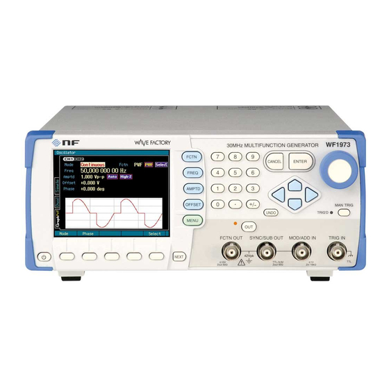
3.1 Panel Components and Operations This section describes the names and functions of the various components on the front and rear panels. 3.1.1 Front panel of WF1973 Figure 3-1. Front Panel of WF1973 Numeric keypad Used for numerical input p. 31... -
Page 19: Rear Panel Of Wf1973
3.1 Panel Components and Operations 3.1.2 Rear panel of WF1973 Figure 3-2. Rear Panel of WF1973 Exhaust vent p. 5 Power supply input p. 6 USB connector GPIB connector Multi-I/O connector Used for sweep, sequence control, sync code output p. 16 Frequency reference output terminal p. -
Page 20: Front Panel Of Wf1974
3. PANELS AND I/O TERMINALS 3.1.3 Front panel of WF1974 Figure 3-3. Front Panel of WF1974 Numeric keypad Used for numerical input p. 31 UNDO key Basic parameter Press to undo setting changes shortcut keys p. 35 Press to allow the waveform, CANCEL key frequency, amplitude, and DC Press to cancel. -
Page 21: Rear Panel Of Wf1974
16 Frequency reference output terminal p. 16 External 10 MHz frequency reference input terminal p. 15 CH2 external modulation/addition input terminal p. 14 CH1 external modulation/addition input terminal p. 14 Figure 3-4. Rear Panel of WF1974 WF1973/WF1974... -
Page 22: I/O Terminals
If a difference in potential exists between the grounds of the BNC connectors, CAUTION do not short circuit these BNC connector grounds, as this may damage the equipment. 3.2.1 Waveform output (FCTN OUT) WF1973 WF1974 FCTN OUT [Insulated from housing] FCTN OUT... -
Page 23: Sync/Sub-Output (Sync/Sub Out)
3.2 I/O Terminals 3.2.2 Sync/sub-output (SYNC/SUB OUT) WF1973 WF1974 SYNC/SUB SYNC/SUB SYNC/SUB [Insulated from housing] [Insulated from [Insulated from housing] housing] A sync signal is output according to the waveform or oscillation status. This signal can be used as the oscilloscope synchronization signal. -
Page 24: External Modulation/Addition Input (Mod/Add In)
3. PANELS AND I/O TERMINALS 3.2.3 External modulation/addition input (MOD/ADD IN) WF1973 WF1974 MOD/ADD MOD/ADD MOD/ADD [Insulated from housing] [Insulated from [Insulated from housing] housing] When the modulation source is external, except for FSK and PSK, an external modulation signal is input. In the case of the FSK and PSK, the external trigger input is used as external modulation signal input. -
Page 25: External 10 Mhz Frequency Reference Input (10 Mhz Ref In)
“4. SYNCHRONIZING MULTIPLE UNITS” in the Application Instruction Manual The frequency accuracies of the connected WF1973 and WF1974 units are all the same as that of the master unit. An external frequency standard can also be used for the master unit. -
Page 26: Frequency Reference Output (Ref Out)
REF OUT REF OUT Use REF OUT to unify the frequency and phase for multiple WF1973, WF1974 units. Connect the frequency reference output of the master unit when multiple units are combined in synchronous connection, or the master WF1973 or WF1974, to the external 10 MHz frequency reference input of the WF1973 or WF1974. -
Page 27: Figure 3-5. Multi-I/O Connector Pin Assignment
Check When not using control input for multi-I/O connector, it is recommended to disable control input to prevent malfunction due to external noise. p. 94 Figure 3-5. Multi-I/O Connector Pin Assignment Figure 3-5. Multi-I/O Connector Pin Assignment WF1973/WF1974... - Page 28 Output voltage TTL level (low: 0.4 V or lower; high: 2.7 V or higher) Signal GND Same potential as housing Connector Mini D-sub 15-pin The connection cable is an option. Contact NF Corporation or an NF distributor for details. MULTIFUNCTION GENERATOR...
-
Page 29: Cautions On Floating Ground Connection
Nor is noise caused by ground-loop a problem in the case of synchronized connection of multiple units of the WF1973 or WF1974. However, in all cases, the floating voltage should be limited to 42 Vpk (DC+AC peak) or lower to prevent electric shocks. -
Page 30: Figure 3-6. Cautions On Floating Ground Connection For Wf1973
3. PANELS AND I/O TERMINALS ■ Cautions on Floating Ground Connection for WF1973 Figure 3-6. Cautions on Floating Ground Connection for WF1973 FCTN OUT ANALOG SYNC/SUB OUT MOD/ADD IN Use with potential difference of 42 Vpk 1 MΩ Use with potential... -
Page 31: Basic Operation
(standby state) Once the power is switched on, a self-check test is automatically executed and the unit becomes operable. ■ Power-off procedure The display goes off. Press the Power on state power switch. The power is switched off (standby state) WF1973/WF1974... -
Page 32: Restoration Of Settings At Power-On
4. BASIC OPERATION 4.1.2 Restoration of settings at power-on When the power is switched on/off with the power switch, the settings before the previous time the power was switched off are restored when the power is switched on again. The output on/off settings at power-on can be set on the Utility screen. p. - Page 33 •The settings before the equipment was powered off last are restored. •The output on/off settings at power-on can be set on the Utility screen. p. 41 Check The previous settings can be restored only if the equipment was powered off using the power switch. WF1973/WF1974...
- Page 34 4. BASIC OPERATION b) Restoration of settings during power supply on/off This applies to switching the power supply on/off at one time for this equipment and other embedded devices when this equipment is mounted in a rack. When the power supply is cut off while the equipment power is on, the equipment power automatically goes on the next time the power supply is reconnected.
-
Page 35: Screen Configuration And Operation
• Uncalibrated status UCal Displayed when the calibration information of the equipment is lost due to a problem, and the prescribed performance cannot be maintained. Since this is a malfunction, notify NF Corporation or an NF distributor. • Overheating status Temp Displayed when the internal temperature of the equipment becomes abnormally high. - Page 36 4. BASIC OPERATION ■ Setting area This area is used to display and set the various parameters. When multiple display formats can be selected, display format switch tabs are displayed on the left side of the screen. p. 27 Due to the large number of setting parameters in the case of modulation, sweep, and burst oscillation, the setting screen consists of two or three pages.
-
Page 37: Switching Display Format With Tabs (Displaying Waveform Graph)
Display format types There are three types of display formats, as follows. ■ Text display [Text] (WF1973) ■ Graph display [Graph] or [Single](WF1974) Displays the settings of one channel in both... - Page 38 4. BASIC OPERATION b) Switching the display format In the example on the left, the Text tab screen is displayed. The Text tab On this screen, the settings are displayed screen is in text form. displayed. Select the Graph tab with the arrow keys or the modify knob.
-
Page 39: Top Menu
■ Utility Various settings and manipulations can be done. p. 39 ■ Store memory The settings can be saved to the setting memory. p. 122 ■ Recall memory The settings can be called from the setting memory. p. 124 WF1973/WF1974... -
Page 40: Basic Settings And Operations
4. BASIC OPERATION 4.3 Basic Settings and Operations 4.3.1 Changing the frequency, amplitude, and other values a) Changing a value with the up/down arrow keys or the modify knob Select the desired item with the arrow keys or the modify knob. In the example on the left, the [Freq] frequency field is selected. - Page 41 If the CANCEL key is pressed instead of the ENTER key, the input value is discarded and the setting remains unchanged. Check During numeric input, the left arrow key serves as the delete key, and the right arrow key as the zero input key. WF1973/WF1974...
- Page 42 4. BASIC OPERATION Check If a setting item is displayed on a soft key, the input field for that item can be opened by pressing that soft key. MULTIFUNCTION GENERATOR...
-
Page 43: Changing The Waveform And Oscillation Mode
The list of choices closes. The setting is changed and the ENTER choice list closes. If the CANCEL key is pressed instead of the ENTER key, the setting remains unchanged and the status of step 1 is returned to. WF1973/WF1974... -
Page 44: Manipulating Shortcut Keys For Changing Basic Parameters
4. BASIC OPERATION 4.3.3 Manipulating shortcut keys for changing basic parameters The choice list or input field for waveform, frequency, amplitude, and DC offset can be immediately opened with the corresponding basic parameter shortcut key. ■ Waveform p. 44 The waveform choice list opens. -
Page 45: Operations Of Enter Key, Cancel Key, And Undo Key
When the UNDO key is pressed again immediately following undo manipulation, the settings are restored to their state before undo. It should be noted, however, that undo does not work for some items. WF1973/WF1974... -
Page 46: Changing The Display Unit
4. BASIC OPERATION 4.3.5 Changing the display unit a) Changing the prefix (unit prefix: k, m, M, etc.) Frequency is used as an example below. The amplitude and pulse width can be changed in a similar manner. Select frequency and then press the ENTER key to open the input field. - Page 47 45. • Changing the amplitude unit (Vp-p, Vpk, Vrms, dBm, dBV) p. 48. • Changing the pulse width time and duty settings p. 61. • Setting the user-defined unit “7. USING USER-DEFINED UNITS” in the Application Instruction Manual WF1973/WF1974...
-
Page 48: Ch1/Ch2 Switching Key And Active Channel (Wf1974 Only)
4. BASIC OPERATION 4.3.6 CH1/CH2 switching key and active channel (WF1974 only) The channel to be set is switched each time the CH1/CH2 switching key is pressed. MENU This key is invalid in setting screens that are channel independent. FCTN OU CH 1/CH 2 NEXT The channel that is to be set is called the “active channel”... -
Page 49: Actions Possible In The Utility Screen
Performs inter-unit synchronization during multiple unit synchronization connection and inter-channel synchronization of the WF1974. “3.3 Phase Synchronization Between Channels” and “4. SYNCHRONIZING MULTIPLE UNITS” in the Application Instruction Manual. User-defined unit setting [User Unit] Sets user-defined units. “7. USING USER-DEFINED UNITS” in the Application Instruction Manual. WF1973/WF1974... - Page 50 4. BASIC OPERATION Remote setting [Remote] Selects GPIB/USB and sets the GPIB address. The USB ID is also displayed. “8.1 Selecting Remote Interface [Remote]” in the Application Instruction Manual. Display setting [Display] Sets the backlight of the display. “8.2 Display Settings [Display]” in the Application Instruction Manual.
-
Page 51: Restoring The Initial Settings
Setting at power-on The waveform output on/off status at power-on can be specified. The output setting at power-on can be selected from the following three. • Off [Off] The output is off. • On [On] The output is on. WF1973/WF1974... - Page 52 4. BASIC OPERATION • Return to previous setting [Last State] The operation differs as follows according to the method used the previous time to set the power off. If the power was switched off the previous time with the power switch on the panel The settings before the power was switched off are restored.
-
Page 53: Setting Methods For Main Items
The oscillation mode can also be set by inputting a number from the numeric keypad while the [Mode] field is selected (without the choice list displayed). WF1973/WF1974... -
Page 54: Setting The Waveform
4. BASIC OPERATION 4.4.3 Setting the waveform Press the FCTN shortcut key to FCTN display waveform choice list. Alternatively, select the [Fctn] field and press the ENTER key to open the ENTER choice list. Waveform Even if there are several setting screens, choice list the [Fctn] field is always displayed at the top right of the first page. -
Page 55: Performing Setting With Period
Then press the ENTER key or the [deg] unit key (soft key) to set the input value and reflect it to the ENTER output. If the ENTER key is used, the unit is also set to deg. WF1973/WF1974... - Page 56 4. BASIC OPERATION b) Items that can be changed in the phase setting The following items can be changed with the phase setting. ■ The phase difference between the sync/sub-output’s reference phase sync output and waveform output can be changed The following example assumes a phase setting of +90°.
- Page 57 For details on sync oscillation and 2-phase oscillation, “3.3 Phase Synchronization Between Channels” and “3.4 Maintaining Both Channels to Same Frequency (2-Channel Ganged Operation, 2-Phase)” in the Application Instruction Manual. CH1 waveform output CH2 waveform output CH2 phase setting – CH1 phase setting WF1973/WF1974...
-
Page 58: Setting The Amplitude
4. BASIC OPERATION 4.4.7 Setting the amplitude a) Setting method Press the AMPTD shortcut key to AMPTD open amplitude input field. Alternatively, select the [Amptd] field and then press the ENTER key to open ENTER Amplitude input the amplitude input field. field Even if there are several setting screens, the [Amptd] field is always displayed on... - Page 59 For example, if the AC amplitude is 5 Vp-p/open, the DC offset range is limited to the range from −7.5 V/open to +7.5 V/open. The maximum value varies according to the output voltage range setting and the external addition input setting. p. 54, p. 57 WF1973/WF1974...
-
Page 60: Setting Dc Offset
4. BASIC OPERATION 4.4.8 Setting DC offset a) Setting method Press the OFFSET shortcut key to OFFSET open offset input field. Alternatively, select the [Offset] field and then press the ENTER key to open ENTER the DC offset input field. DC offset input Even if there are several setting screens, field... -
Page 61: Setting The Output Level With High Level/Low Level
Soft key: High → Amptd, Low → Offset b) AC+DC limitation The high level and low level are limited to the range of −10 V to + 10 V/open. The maximum range varies according to the output voltage range setting and the external WF1973/WF1974... -
Page 62: Setting The Waveform Polarity And Amplitude Range
4. BASIC OPERATION addition input setting. p. 54, p. 57 4.4.10 Setting the waveform polarity and amplitude range a) Setting method Select the polarity/amplitude range icon to Select the the right of the waveform name to display polarity/amplitude range icon and current polarity/amplitude range... - Page 63 1 bit compared to ±FS. • The amplitude setting when the amplitude setting is ±FS is Vp-p, and in the case of −FS/ 0 or 0/+FS, it is Vpk. In either case, the amplitude refers to the peak-to-peak size of the waveform. WF1973/WF1974...
-
Page 64: How To Use Auto Range/Range Hold For The Output Voltage
4. BASIC OPERATION 4.4.11 How to use auto range/range hold for the output voltage Since auto range is set as part of the initial settings, the optimum range is automatically selected according to the amplitude and DC offset (including settings with high level and low level). -
Page 65: Setting The Load Impedance
CANCEL key. b) Conversion formula Conversion is done with the following formula. Load impedance setting value: R (Ω) load Load-open output voltage: V open Output voltage setting value (load-end voltage): V load load -------------------------- - × load open load WF1973/WF1974... - Page 66 4. BASIC OPERATION Check ・The output impedance is constant at 50 Ω. ・The output impedance error and output voltage error are not corrected. The output voltage accuracy specification is the load-open value. MULTIFUNCTION GENERATOR...
-
Page 67: Adding External Signal
An external signal can be added to the waveform output of this equipment. a) Connecting the addition signal Connect the addition signal to the external modulation/addition input (MOD/ADD IN) BNC terminal on the front panel and the rear panel in the WF1973 and WF1974, respectively. WF1973 WF1974... - Page 68 4. BASIC OPERATION Once the external addition settings have been completed, select [OK] in the lower part of the window and then press the ENTER key to apply the external ENTER addition setting change and close the window. To not change the external addition Select [OK] and setting, select [Cancel] in the lower part of then press the...
-
Page 69: Setting The Square Wave Duty
The desired condition can also be set by inputting a number from the numeric keypad while the [Extend] field is selected (without the choice list displayed). WF1973/WF1974... - Page 70 4. BASIC OPERATION c) Difference between normal and extended variable duty range Variable Range Characteristics Normal Setting range: 0.0100% to 99.9900% • Range in which the duty can be changed with little jitter and no pulse loss • The higher the frequency, the narrower the duty setting range. •...
-
Page 71: Setting The Pulse Width And Leading/Trailing Edge Time Of A Pulse Wave
When the pulse width time input field is open and the current pulse width time is displayed, the [Duty] soft key is displayed. Press this key to open the pulse width duty input field and change the item display from [Width] to [Duty]. The [Duty] soft key changes to [Width]. WF1973/WF1974... - Page 72 4. BASIC OPERATION ○ Pulse width duty → Pulse width time When the pulse width duty input field opens and the current pulse width duty is displayed, the [Width] soft key is displayed. Press this soft key to open the pulse width time input field and change the item display from [Duty] to [Width].
- Page 73 trailing edge time For example, when the leading edge time and the trailing edge time are each set to 100 ns at 1 kHz, the pulse width time can vary in the range of 170 ns to 999.83 µs. WF1973/WF1974...
-
Page 74: Setting The Ramp Wave Symmetry
4. BASIC OPERATION 4.4.16 Setting the ramp wave symmetry The waveform is assumed to be set to [Ramp] (ramp wave). For the waveform setting method, p. 44. The symmetry setting unit is % only. Setting and display with time is not possible. a) Symmetry setting method Select the [Symm] field and then press the ENTER key to open the symmetry... -
Page 75: Using Parameter-Variable Waveforms
These settings are done independently for each waveform, and can be changed even when the selection screen has been exited. Each waveform has up to 5 specific parameters. Set the desired value for each one of these parameters. WF1973/WF1974... - Page 76 4. BASIC OPERATION To return the variable parameter values to their initial value, press the [Reset] soft key. The change is instantly reflected to the output waveform, and the shape of the set waveform is displayed in graph form. For details on the variable parameters, “1.
-
Page 77: Using Arbitrary Waveforms
Arbitrary waveforms cannot be created on this screen. For how to create arbitrary waveforms, data fomat, and memory size, “2. CREATING ARBITRARY WAVEFORMS” in the Application Instruction Manual. The name changing method is the same as for the setting memory. Names of up to 20 characters can be set. p. 123 WF1973/WF1974... - Page 78 4. BASIC OPERATION To apply the changes and quit the selection screen, press the [OK] soft key. To discard the changes and quit the selection screen, press the [Cancel] soft key. The changes can also be discarded and the selection screen exited by pressing a basic parameter shortcut key (the operation differs from that in the parameter-variable waveform selection screen).
-
Page 79: Modulation Setting And Manipulation
• AM: Amplitude Modulation p. 79 • AM(DSB-SC): Amplitude Modulation(Double Side Band − Suppressed Carrier) This is AM that does not include the carrier frequency component. p. 80 • DC offset modulation p. 81 • PWM: Pulse Width Modulation p. 82 WF1973/WF1974... -
Page 80: Screen For Modulation Setting And Manipulation
4. BASIC OPERATION 4.7.2 Screen for modulation setting and manipulation This subsection describes the screen configuration used in common for the modulated oscillation mode. The settings and manipulations are done on the Oscillator setting screen. The Oscillator setting screen is displayed as “Oscillator” in the top left part of the screen. When another screen is displayed, press the MENU key to display the top menu, then select MENU... - Page 81 This is the frequency of the internal modulation source. p. 72 Sync output [SyncOut] This is the output signal from the sync/sub-output terminal. Waveform basic phase sync, internal modulation sync, and internal modulation waveform can be chosen from. p. 74 WF1973/WF1974...
-
Page 82: Common Modulation Settings And Manipulations
4. BASIC OPERATION 4.7.3 Common modulation settings and manipulations This subsection describes the settings and manipulations that are common to all types of modulation. a) To set the oscillation mode to modulation → Oscillation mode setting On the Oscillator setting screen, set [Mode] (oscillation mode) to [Modulation]. - Page 83 To stop modulation → [Stop] soft key Modulation can be paused. When the [Stop] soft key is pressed during modulation, modulation stops and the carrier signal is output without being modulated. The oscillation mode remains the modulated oscillation mode. WF1973/WF1974...
- Page 84 4. BASIC OPERATION i) To output modulation sync signal, modulation waveform signal → Sync output setting Perform the sync output setting with [SyncOut] (sync output) on the 2nd page of the setting screen. The sync output setting can be chosen from the following three. ・Signal synchronized with reference phase of waveform [Sync] ・Signal synchronized with internal modulation waveform [ModSync] ・Internal modulation waveform [ModFctn]...
-
Page 85: Setting Fm
If [Source] (modulation source) is set to [Int] (internal), set [ModFctn] (modulation waveform) and [ModFreq] (modulation frequency). If [Source] (modulation source) is set to [Ext] (external), input the modulation signal to the external modulation/addition input terminal. In the case of ±1 V input, the prescribed peak frequency deviation results. WF1973/WF1974... -
Page 86: Setting Fsk
4. BASIC OPERATION 4.7.5 Setting FSK This is binary frequency shift modulation by which the output frequency switches between the carrier frequency and hop frequency according to the modulation signal. For the manipulation methods that are common with the modulation setting screen, refer to pp. -
Page 87: Setting Pm
If [Source] (modulation source) is set to [Int] (internal), set [ModFctn] (modulation waveform) and [ModFreq] (modulation frequency). If [Source] (modulation source) is set to [Ext] (external), input the modulation signal to the external modulation/addition input terminal. In the case of ±1 V input, the prescribed peak frequency deviation results. WF1973/WF1974... -
Page 88: Setting Psk
4. BASIC OPERATION 4.7.7 Setting PSK This is binary phase shift modulation by which the output phase is offset according to the modulation signal. For the manipulation methods that are common with the modulation setting screen, refer to pp. 70 and 72. a) PSK example Since the phase changes suddenly, the output signal waveform is non-continuous. -
Page 89: Setting Am
If [Source] (modulation source) is set to [Int] (internal), set [ModFctn] (modulation waveform) and [ModFreq] (modulation frequency). If [Source] (modulation source) is set to [Ext] (external), input the modulation signal to the external modulation/addition input terminal. In the case of ±1 V input, the prescribed modulation depth results. WF1973/WF1974... -
Page 90: Setting Am (Dsb-Sc)
4. BASIC OPERATION 4.7.9 Setting AM (DSB-SC) The output amplitude varies according to the instantaneous value of the modulation signal. This is AM without the carrier frequency component. DSB-SC stands for Double Side Band − Suppressed Carrier. For the manipulation methods that are common with the modulation setting screen, refer to pp. -
Page 91: Setting Dc Offset Modulation
If [Source] (modulation source) is set to [Int] (internal), set [ModFctn] (modulation waveform) and [ModFreq] (modulation frequency). If [Source] (modulation source) is set to [Ext] (external), input the modulation signal to the external modulation/addition input terminal. In the case of ±1 V input, the prescribed peak DC offset deviation results. WF1973/WF1974... -
Page 92: Setting Pwm
4. BASIC OPERATION 4.7.11 Setting PWM The duty of square waves and pulse waves varies according to the instantaneous value of the modulation signal. For the manipulation methods that are common with the modulation setting screen, refer to pp. 70 and 72. a) PWM example The duty of the output signal grows larger when the modulation signal swings to the positive side. -
Page 93: Sweep Setting And Manipulation
Set the oscillation Indicates that the mode to [Sweep] 1st page is displayed Press the NEXT key to display There are two the 2nd page stages of soft keys WF1973/WF1974... - Page 94 4. BASIC OPERATION c) 2nd page of setting screen: Screen for the main sweep settings The figure is an example that shows frequency selection as the sweep type. Sweep start value Indicates that the 2nd page is Sweep stop value displayed Sweep type Sweep time...
- Page 95 1 cycle and 1/2 cycle. Normally, the unit is set to 1 cycle. p. 89 Sync output [SyncOut] This is the output signal from the sync/sub-output terminal. Waveform reference phase sync, sweep sync, sweep marker, and sweep X drive can be selected from. p. 92 WF1973/WF1974...
-
Page 96: Common Sweep Settings And Manipulations
4. BASIC OPERATION 4.8.3 Common sweep settings and manipulations This subsection describes the settings and manipulations that are used in common regardless of the item to be swept. a) To set the oscillation mode to sweep → Oscillation mode setting On the Oscillator setting screen, set [Mode] (oscillation mode) to [Sweep]. - Page 97 Set [SwpMode] (sweep mode) on the 2nd page of the setting screen to [Cont] (continuous). No trigger signal is required. The transition time from the start value to the stop value is set with [Time] (sweep time) on the 2nd page. WF1973/WF1974...
- Page 98 4. BASIC OPERATION Since the sweep time is the transition time from the start value to the stop value, when the sweep function is shuttle, the repeat period is twice the length of the sweep time setting, as shown in the following figure. Continuous one-way sweep Stop value Sweep value...
- Page 99 (1 cycle) is set, whole integer cycle oscillation results. When oscillation is stopped, it always stops either in 1-cycle or half-cycle units according to the [OscStop] (oscillation stop unit) setting, and the oscillation time is usually longer than the sweep time setting. WF1973/WF1974...
- Page 100 4. BASIC OPERATION Gated single-shot one-way sweep Trigger Stop value Sweep value Start value Start value Sweep time Frequency sweep example Gated single-shot shuttle sweep Trigger Stop value Sweep value Start value Sweep time Sweep time Frequency sweep example Check In the case of phase sweep, the start phase setting is the oscillation start phase, and the stop phase setting is the oscillation stop phase.
- Page 101 The [SttState] soft key is displayed in the sweep start value output state or in the sweep stop value output state. If the [SttState] soft key is not displayed, press the [ ▼ 2/2] soft key on the right end to switch the soft key sets. WF1973/WF1974...
- Page 102 4. BASIC OPERATION In the case of gated single-shot sweep, the state is the start value oscillation state. To stop oscillation, press the [Stop] soft key. p) To output the sweep stop value → [StpState] soft key Press the [StpState] soft key to set the sweep stop value output state. The status of the equipment under test at the sweep stop value can be checked.
- Page 103 (marker disabled) stop value Low from Low from Sweep sync signal start value to start value to SwpSync+Mkr marker value marker value (marker enabled) +3 V +3 V Sweep X drive signal X-Drive Sweep time Sweep time Sweep time WF1973/WF1974...
- Page 104 4. BASIC OPERATION r) To substitute center value to marker value, or substitute marker value to center value When the [Ctr ⇒ Mkr] soft key on the 2nd page of the setting screen is pressed, the center value is substituted to the marker value. When the [Mkr ⇒ Ctr] soft key is pressed, the marker value is substituted to the center value.
-
Page 105: Setting Frequency Sweep
Setting with [Center] (center frequency) and [Span] (span frequency) instead of the start frequency and stop frequency is also possible. p. 86 When the sweep mode is single-shot or gated single-shot, [Trig] (trigger condition) must be set. p. 90 WF1973/WF1974... - Page 106 4. BASIC OPERATION Set the following items as needed. • Marker frequency [Marker] (2nd page of setting screen) p. 92 • Stop level [StpLvl] (3rd page of setting screen) p. 89 This setting can be used only for gated single-shot sweep. •...
-
Page 107: Setting Phase Sweep
• Start phase [Start] • Stop phase [Stop] • Sweep time [Time] This is the transition time from the start phase to the stop phase. p. 87 • Sweep mode [SwpMode] Continuous, single-shot, and gated single-shot can be chosen from. p. 87 WF1973/WF1974... - Page 108 4. BASIC OPERATION • Sweep function [SwpFctn] One-way/shuttle can be chosen from. p. 86 Setting with [Center] (center phase) and [Span] (span phase) instead of the start phase and stop phase is also possible. p. 86 When the sweep mode is single-shot or gated single-shot, [Trig] (trigger condition) must be set.
-
Page 109: Setting Amplitude Sweep
Setting with [Center] (center amplitude) and [Span] (span amplitude) instead of the start amplitude and stop amplitude is also possible. p. 86 When the sweep mode is single-shot or gated single-shot, [Trig] (trigger condition) must be set. p. 90 WF1973/WF1974... - Page 110 4. BASIC OPERATION Set the following items as needed. • Marker amplitude [Marker] (2nd page of setting screen) p. 92 • Stop level [StpLvl] (3rd page of setting screen) p. 89 This setting can be used only for gated single-shot sweep. •...
-
Page 111: Setting Dc Offset Sweep
Setting with [Center] (center DC offset) and [Span] (span DC offset) instead of start DC offset and stop DC offset is also possible. p. 86 When the sweep mode is single-shot or gated single-shot, [Trig] (trigger condition) must be set. p. 90 WF1973/WF1974... - Page 112 4. BASIC OPERATION Set the following items as needed. • Marker DC offset [Marker] (2nd page of setting screen) p. 92 • Stop level [StpLvl] (3rd page of setting screen) p. 89 This setting can be used only for gated single-shot sweep. •...
-
Page 113: Setting Duty Sweep
Continuous, single-shot, and gated single-shot can be chosen from. p. 87 • Sweep function [SwpFctn] One-way/shuttle can be chosen from. p. 86 Setting with [Center] (center duty) and [Span] (span duty) instead of the start duty and stop duty is also possible. p. 86 WF1973/WF1974... - Page 114 4. BASIC OPERATION When the sweep mode is single-shot or gated single-shot, [Trig] (trigger condition) must be set. p. 90 Set the following items as needed. • Marker duty [Marker] (2nd page of setting screen) p. 92 • Stop level [StpLvl] (3rd page of setting screen) p.
-
Page 115: Burst Setting And Manipulation
• Gate oscillation Oscillation is done in integer cycles or half cycles while the gate is on. p. 113 • Triggered gate oscillation This is gate oscillation that switches the gate on/off each time a trigger is received. p. 118 WF1973/WF1974... -
Page 116: Auto Burst
4. BASIC OPERATION 4.9.2 Auto burst Oscillation and stop are automatically repeated with the respectively specified wave number. No trigger signal is required. Settings and manipulations are done on the Oscillator setting screen. “Oscillator” is displayed at the top left of the Oscillator setting screen. When another screen is displayed, pressing the MENU key displays the top menu, so select [Oscillator] and then press MENU... - Page 117 Set [Mark[ (mark wave number) and [Space] (space wave number) on the 2nd page of the setting screen. Each wave number is normally set to an integer value. [StpLvl] (stop level) on the 2nd page of the setting screen is normally set to [Off] (off). p. 108 WF1973/WF1974...
- Page 118 4. BASIC OPERATION f) To start auto burst → Automatically starts When, in the auto burst mode, the mode is set to the burst oscillation mode, burst starts automatically. However, if the burst setting is improper, burst oscillation will not start. ([Conflict!] is displayed in the top right part of the screen.) When the [?] soft key appearing at the left end is pressed, a message about the inappropriate setting is displayed.
-
Page 119: Trigger Burst
NEXT key. NEXT Next, set [BrstMode] (burst mode) on the 2nd page of the burst oscillation mode setting screen to [Trigger] (trigger burst). Select [Trigger] in [BrstMode] and then press the ENTER key WF1973/WF1974... - Page 120 4. BASIC OPERATION c) Trigger burst setting screen ■ 1st page: Screen for the basic parameters These are the common setting items that are common to all the oscillation modes. Indicates that the 1st page is displayed Set the oscillation mode to [Burst].
- Page 121 This setting is done with [SyncOut] (sync output) on the 2nd page of the setting screen. One of the following two settings can be selected. • Signal synchronized with the reference phase of the waveform [Sync] • Signal synchronized with burst oscillation [BrstSync] WF1973/WF1974...
- Page 122 4. BASIC OPERATION ■ When [Sync] is selected A TTL level signal that rises at the reference phase of the waveform is output from the sync/ sub-output terminal. ■ When [BrstSync] is selected A TTL level signal synchronized with the burst oscillation is output from the sync/sub- output terminal.
-
Page 123: Gate Oscillation
NEXT key. NEXT Next, set [BrstMode] (burst mode) on the 2nd page of the burst oscillation mode Select [Gate] in setting screen to [Gate] (gate oscillation). [BrstMode] and then press the ENTER key WF1973/WF1974... - Page 124 4. BASIC OPERATION c) Gate oscillation setting screen ■ 1st page: Screen for the basic parameters These are the common setting items that are common to all the oscillation modes. Indicates that the 1st page is displayed Set the oscillation mode to [Burst] Press the NEXT Oscillation start/stop...
- Page 125 • Signal synchronized with the reference phase of the waveform [Sync] • Signal synchronized with burst oscillation [BrstSync] ■ When [Sync] is selected A TTL level signal that rises at the reference phase of the waveform is output from the sync/ sub-output terminal. WF1973/WF1974...
- Page 126 4. BASIC OPERATION ■ When [BrstSync] is selected A TTL level signal synchronized with the gate oscillation is output from the sync/sub-output terminal. As shown in the following figure, this signal is low during oscillation and high during oscillation stop. Note that this differs from the gate signal. When the signal during burst is observed with an oscilloscope, it can be used as the trigger signal for the oscilloscope.
- Page 127 Further, since noise has no phase, the stop level setting is always enabled. The next figure is an example of noise gate oscillation when the stop level is 0%. Gate signal Gate on Gate off Gate on Burst sync signal Oscillation Stop Oscillation Signal output Stop level: 0% WF1973/WF1974...
-
Page 128: Triggered Gate Oscillation
4. BASIC OPERATION 4.9.5 Triggered gate oscillation Triggered gate oscillation is gate oscillation that switches the gate on/off each time a trigger is received. The settings and manipulations are done on the Oscillator setting screen. “Oscillator” is displayed at the top left of the Oscillator setting screen. When another screen is displayed, press the MENU key to display the top menu, then select [Oscillator] and press the MENU... - Page 129 Set [Phase] (oscillation start/stop phase) on the 1st page of the setting screen. [StepLvl] (stop level) on the 2nd page of the setting screen is set to [Off] normally. p. 121 [OscStop] (oscillation stop unit) on the 2nd page of the setting screen is set to [Cycle] (1 WF1973/WF1974...
- Page 130 4. BASIC OPERATION cycle) normally. p. 121 A trigger is required for triggered gate oscillation. Refer to the following item. f) Trigger settings for triggered gate oscillation The trigger can be selected from internal trigger oscillator, external signal, manual trigger key manipulation, and remote trigger manipulation.
- Page 131 Noise triggered gate oscillation Noise having no cycle, the gate-on period is the oscillation period, and the gate-off period is the period stop interval. Further, since noise has no phase, the stop level setting is always enabled. p. 117 WF1973/WF1974...
-
Page 132: Saving And Recalling Settings
SAVING AND RECALLING SETTINGS 5.1 Saving Settings The current setting conditions can be saved to the setting memory and then recalled for use. The setting saving operation is done on the Store Memory screen. The settings when the power supply is cut off/restored are saved to setting memory No. 1. p. - Page 133 0 1 2 3 4 5 6 7 8 9 ’ ( ) * + , - . / : ; < = > ? @ [ ] \ ^ _ ` { | } ~ space ! # $ % & WF1973/WF1974...
-
Page 134: Recalling Settings
5. SAVING AND RECALLING SETTINGS 5.2 Recalling Settings The setting conditions saved to the setting memory can be recalled for use. The setting recall operation is done on the Recall Memory screen. At shipping, the same contents as the initial settings are saved to all the setting memories. a) Setting recall procedure Press the MENU key to display the... - Page 135 [Rename] soft key to open the setting setting memory memory name input field. name input field The name input method is the same as in the case of the Store Memory screen. p. 123 WF1973/WF1974...
-
Page 136: List Of Initial Settings
LIST OF INITIAL SETTINGS The following initial settings are restored by executing [Reset] (setting initialization) on the Utility screen. These items are also the targets to be saved in the setting memory (except for the output on/off setting). The arbitrary waveform memory, setting memory, sequence memory, user-defined unit definition, output setting at power-on, panel operation setting, and remote setting are not initialized. - Page 137 Oscillation stop unit during gate 1 cycle Sync/sub-output Burst synchronization ■ 2-channel operation (WF1974 only) Channel mode Independent Frequency difference 0 Hz Frequency ratio Same-value setting ■ Other Use of user-defined unit Released External 10 MHz frequency reference Disabled External addition WF1973/WF1974...
- Page 138 6. LIST OF INITIAL SETTINGS The following settings are factory-default settings for items which do not return to their initial values even if initialization is executed once the settings are changed by the user. ■ User-defined unit definition Unit name usr1 to usr6 Calculation formula (h+n)*m...
-
Page 139: Specifications
Up to 128 waveforms or 4 M words (combined total for channels 1 and 2) Saved to non-volatile memory Waveform data amplitude resolution 16 bits Sampling rate 120 MS/s Polarity Normal, inverted (selectable) Amplitude range −FS/0, ±FS, 0/+FS (selectable) Output bandwidth 25 MHz, −3 dB WF1973/WF1974... -
Page 140: Frequency, Phase
7. SPECIFICATIONS 7.3 Frequency, Phase Frequency setting range Oscillation Mode Continuous, Modulated, Sweep (Gated Single- Sequence Sweep (Continuous, Shot), Burst Single-Shot) Waveform Sine 0.01 µHz to 30 MHz 0.01 µHz to 10 MHz 0.01 µHz to 10 MHz 0.01 µHz to 15 MHz 0.01 µHz to 10 MHz 0.01 µHz to 10 MHz Square... -
Page 141: Load Impedance Setting
±0.5 dB (±0.8 dB at amplitude setting of 2.8 Vp-p/50 Ω or higher) Condition: Amplitude setting 50 mVp-p to 10 Vp-p/50 Ω, reference frequency 1 kHz Total harmonic distortion 10 Hz to 20 kHz 0.2% or less Condition: Amplitude setting of 0.5 Vp-p to 10 Vp-p/50 Ω WF1973/WF1974... -
Page 142: Square Wave
7. SPECIFICATIONS Harmonic spurious 0.5 Vp-p to 2 Vp-p/50 Ω 2 Vp-p to 10 Vp-p/50 Ω Condition: Amplitude setting 1 MHz or lower −60 dBc or lower −60 dBc or lower 1 MHz to 10 MHz −50 dBc or lower −43 dBc or lower −40 dBc or lower −30 dBc or lower... -
Page 143: Ramp Wave
Remark: In the case of a positive/negative conduction angle, back/front conduction angle Staircase Staircase shaped sine wave sine Number of steps (2 to 100) Multi-cycle Waveform obtained by continuing sine for several cycles sine Number of cycles (0.01 to 50.00) Start phase (−360.00° to 360.00°) WF1973/WF1974... - Page 144 7. SPECIFICATIONS b) Transient sine group Waveform Waveform Description and Variable Parameters Name Example On-phase Sine wave with slope into on state controlled Complete-on phase (0.00° to 360.00°) sine On-slope time (0.00% to 50.00% of basic period) Off-phase Sine wave with slope into off state controlled Off-phase (0.00°...
- Page 145 Leading delay (0.00% to 100.00% of basic period) Rising-slope width (0.00% to 100.00% of basic period) Upper base width (0.00% to 100.00% of basic period) Falling-slope width (0.00% to 100.00% of basic period) Offset (0.00% to 100.00%) WF1973/WF1974...
-
Page 146: Modulated Oscillation Mode
Input impedance 10 kΩ, unbalanced Input frequency DC to 25 kHz Input connector Front panel (WF1973) / rear panel (WF1974) BNC receptacle Shared with external addition input, cannot be used simultaneously with adding operation External modulation input (FSK, PSK) Polarity... -
Page 147: Modulation Conditions
Carrier waveform Standard waveform and arbitrary waveform Peak deviation setting range 0 V to 10 V/open ■ PWM Carrier waveform Square wave, pulse wave Peak deviation setting range Square wave Normal variable duty range 0.0000% to 49.9900% (0.0001% resolution) WF1973/WF1974... -
Page 148: Sweep Oscillation Mode
7. SPECIFICATIONS Extended variable duty range 0.0000% to 50.0000% (0.0001% resolution) Pulse wave 0.0000% to 49.9000% (0.0001% resolution) 7.7 Sweep Oscillation Mode 7.7.1 General Sweep types Frequency, phase, amplitude, DC offset, duty Sweep functions One-way (ramp waveform shape), shuttle (triangular waveform shape) (selectable) Linear, log (frequency sweep only) (selectable) Sweep range setting... -
Page 149: Sweep Conditions
Triggered gate Gate oscillation switched on/off by gate upon trigger Target waveforms Auto, trigger burst Standard waveform other than noise and DC, and arbitrary waveform Gate, triggered gate Standard waveform other than DC, and arbitrary waveform WF1973/WF1974... -
Page 150: Triggers
Minimum pulse width 50 ns Input impedance 10 kΩ (pulled up to +3.3 V), unbalanced Input connector Front panel (WF1973) / rear panel (WF1974) BNC receptacle Manual trigger Panel key operation Applications Used for single-shot sweep, gated single-shot sweep,... -
Page 151: Sequence
Start or state branch, stop, hold/resume, event branch Sequence external trigger input (start trigger) Polarity Positive, negative, off (selectable) Input connector Use of external trigger input on CH1 side. Input voltage and input impedance follow the external trigger input specifications. WF1973/WF1974... -
Page 152: Other I/Os
10 MHz (±0.5% (±50 kHz)) Input waveform Sine wave or square wave (50 ±5% duty) Input connector Rear panel, BNC receptacle Frequency reference output (for synchronizing multiple WF1973, WF1974 units) Output voltage 1 Vp-p/50 Ω square wave 50 Ω, AC coupled Output impedance... -
Page 153: 2-Channel Ganged Operation (Wf1974 Only)
Frequency ratio N:M setting range 1 to 9,999,999 (for each of N and M) N:M = CH2 frequency:CH1 frequency Phase synchronization Automatically executed during channel mode switching Time difference between channels during 2-phase ±20 ns or less (±10 ns or less typ.) Condition: Same waveform (sine or square) WF1973/WF1974... -
Page 154: Synchronous Operation Of Multiple Units
7. SPECIFICATIONS 7.13 Synchronous Operation of Multiple Units Connection Connection method 1 Master unit Slave unit Slave unit Slave unit 10MHz 10MHz 10MHz 10MHz REF IN REF IN REF IN REF IN 50 Ω External reference use possible termination T divider T divider resistor Connection method 2... -
Page 155: Other Functions
Power supply voltage range 100 V AC to 230 V AC ±10% (250 V or lower) Power supply frequency range 50 Hz/60 Hz ±2 Hz Power consumption WF1973: 50 VA or less WF1974: 75 VA or less Overvoltage category Ⅱ... - Page 156 7. SPECIFICATIONS Warm-up time 30 minutes or more typ. Pollution degree External dimensions 216 (W) 88 (H) 332 (D) mm (excluding projections) × × Weight Approx. 2.1 kg (excluding accessories, weight of main unit only) Safety and EMC Applied only to models with the CE marking displayed on the rear panel Safety EN61010-1:2001 EN61326:1997 + A1:1998 + A2:2001 + A3:2003...
-
Page 157: External Dimensions (Wf1973)
7.17 General Characteristics ■ External dimensions (WF1973) WF1973/WF1974... -
Page 158: External Dimensions (Wf1974)
7. SPECIFICATIONS ■ External dimensions (WF1974) MULTIFUNCTION GENERATOR... -
Page 159: Rack Mounting Dimensions
RACK MOUNTING DIMENSIONS RACK MOUNTING DIMENSIONS ■ Inch rack mounting dimensions (for 1 unit) WF1973/WF1974... -
Page 160: Inch Rack Mounting Dimensions (For 2 Units)
RACK MOUNTING DIMENSIONS ■ Inch rack mounting dimensions (for 2 units) MULTIFUNCTION GENERATOR... -
Page 161: Millimeter Rack Mounting Dimensions (For 1 Unit)
RACK MOUNTING DIMENSIONS ■ Millimeter rack mounting dimensions (for 1 unit) WF1973/WF1974... -
Page 162: Millimeter Rack Mounting Dimensions (For 2 Units)
RACK MOUNTING DIMENSIONS ■ Millimeter rack mounting dimensions (for 2 units) MULTIFUNCTION GENERATOR... -
Page 163: Index
......28 AC+DC limitation ......49 accessories check ...........4 ENTER key ..........35 active channel ..........38 external dimensions (WF1973) ....147 adding external signal ........57 external dimensions (WF1974) ....148 amplitude range ........52 external frequency reference ....25 amplitude setting ........48... - Page 164 LINE ..............6 overheating ..........25 load impedance setting .......55 panel MAN TRIG key ....90 front panel of WF1973 ......8 MENU key ...........29 front panel of WF1974 ......10 MOD/ADD IN ..........14 rear panel of WF1973 ......9 modify knob ..........30 rear panel of WF1974 ......
- Page 165 ... 121 sawtooth wave sweep ......86 oscillation in half-cycle units ....121 screen for sweep setting and start triggered gate oscillation ... 120 manipulation ........83 start/stop phase ........119 shuttle sweep .........87 stop level ..........121 WF1973/WF1974...
- Page 166 sync signal ..........120 trigger settings ........120 TRIG’D lamp ...... 90 UCal .............25 uncalibrated ..........25 UNDO key ...........35 unit changing ..........36 unit of amplitude changing ......48 user-defined unit .........37 Utility screen function ........39 Vpk ............48 Vp-p ............48 Vrms .............48 warranty ............157 waste disposal ..........
-
Page 167: Warranty
All NF products are warranted against defects in materials and workmanship for a period of one year from the date of shipment. During the warranty period of, NF will, at its option, either will repair the defective product without any charge for the parts and labor, or either repair or replace products which prove to be defective. - Page 168 However, we assume no responsibility for any damage regarding the contents of this manual. ・We assume no responsibility for influences resulting from the operations in this manual. WF1973/WF1974 Instruction Manual (Basics) NF CORPORATION 3-20 Tsunashima Higashi 6-chome, Kohoku-ku, Yokohama-shi 223-8508, JAPAN Phone: 81-45-545-8128 Fax: 81-45-545-8187 http://www.nfcorp.co.jp/...
- Page 169 NF Corporation 6-3-20, Tsunashima-higashi, Kohoku-ku, Yokohama 223-8508 JAPAN...
Need help?
Do you have a question about the WF1973 and is the answer not in the manual?
Questions and answers