Table of Contents
Advertisement
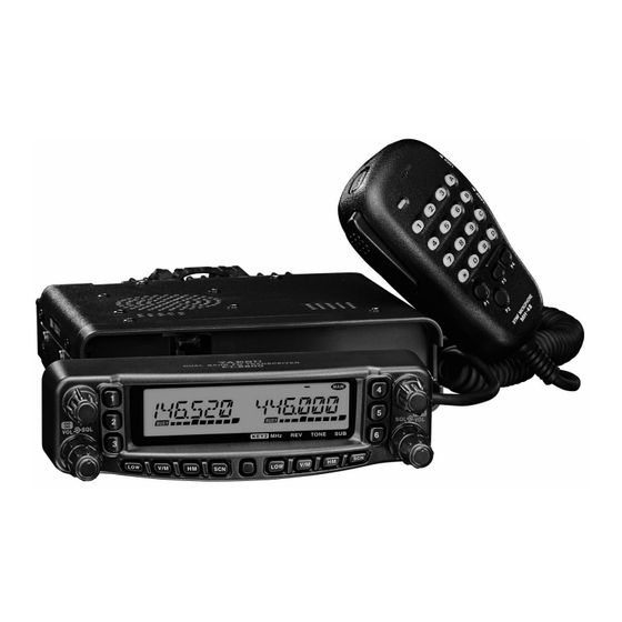
DUAL BAND FM TRANSCEIVER
FT-8800R
O
M
PERATING
ANUAL
VERTEX STANDARD CO., LTD.
4-8-8 Nakameguro, Meguro-Ku, Tokyo 153-8644, Japan
VERTEX STANDARD
US Headquarters
10900 Walker Street, Cypress, CA 90630, U.S.A.
International Division
8350 N.W. 52nd Terrace, Suite 201, Miami, FL 33166, U.S.A.
YAESU EUROPE B.V.
P.O. Box 75525, 1118 ZN Schiphol, The Netherlands
YAESU UK LTD.
Unit 12, Sun Valley Business Park, Winnall Close
Winchester, Hampshire, SO23 0LB, U.K.
Downloaded by
VERTEX STANDARD HK LTD.
RadioAmateur.EU
Unit 5, 20/F., Seaview Centre, 139-141 Hoi Bun Road,
Kwun Tong, Kowloon, Hong Kong
Advertisement
Table of Contents

Related Manuals for Yaesu CT-39A


Summary of Contents for Yaesu CT-39A
- Page 1 DUAL BAND FM TRANSCEIVER FT-8800R PERATING ANUAL VERTEX STANDARD CO., LTD. 4-8-8 Nakameguro, Meguro-Ku, Tokyo 153-8644, Japan VERTEX STANDARD US Headquarters 10900 Walker Street, Cypress, CA 90630, U.S.A. International Division 8350 N.W. 52nd Terrace, Suite 201, Miami, FL 33166, U.S.A. YAESU EUROPE B.V.
-
Page 2: Table Of Contents
Introduction ... 1 Specifications ... 2 Accessories & Options ... 3 Supplied Accessories ... 3 Optional Accessories ... 3 Installation ... 4 Preliminary Inspection ... 4 Installation Tips ... 4 Safety Information ... 5 Antenna Considerations ... 6 Mobile Installation ... 8 Transceiver Installation ... -
Page 3: Introduction
The FT-8800R is a ruggedly-built, high quality Dual Band FM transceiver providing 50 Watts of power output on the 144 MHz Amateur band and 35 Watts on the 430 MHz band. The high power output of the FT-8800R is produced by its RD70HVF1 Power MOS FET amplifier, with a direct-flow heat sink and thermostatically-controlled cooling fan maintain- ing a safe temperature for the transceiver’s circuitry. -
Page 4: Specifications
PECIFICATIONS Frequency Range: Channel Steps: Modes of Emission: Antenna Impedance: Frequency Stability: Operating Temperature Range: –4° F ~ +140° F (–20 °C ~ +60 °C) Supply Voltage: Current Consumption (Approx.): RX: 0.5 A (Squelched) Case Size (W x H x D): Weight (Approx.): Output Power: Modulation Type:... -
Page 5: Accessories & Options
AC Power Supply (25A: USA only) FP-1030A AC Power Supply (30A) CT-39A Packet Interface Cable Availability of accessories may vary. Some accessories are supplied as standard per local requirements, while others may be unavailable in some regions. Consult your Yaesu dealer... -
Page 6: Installation
NSTALLATION This chapter describes the installation procedure for integrating the FT-8800R into a typi- cal amateur radio station. It is presumed that you possess technical knowledge and concep- tual understanding consistent with your status as a licensed radio amateur. Please take some extra time to make certain that the important safety and technical requirements detailed in this chapter are followed closely. -
Page 7: Safety Information
The FT-8800R is an electrical apparatus, as well as a generator of RF (Radio Frequency) energy, and you should exercise all safety precautions as are appropriate for this type of device. These safety tips apply to any device installed in a well-designed amateur radio station. -
Page 8: Antenna Considerations
NSTALLATION NTENNA ONSIDERATIONS The FT-8800R is designed for use with antennas presenting an impedance of near 50 Ohms at all operating frequencies. The antenna (or a 50 Ohm dummy load) should be connected whenever the transceiver is turned on, to avoid damage that could otherwise result if trans- mission occurs accidentally without an antenna. - Page 9 For reference, the chart below shows approximate loss figures for typically-available co- axial cables frequently used in VHF/UHF installations. Loss in dB per 30 m (100 feet) for Selected 50-Ohm Coaxial Cables (Assumes 50-ohm Input/Output Terminations) RG-58A RG-58 Foam RG-213 RG-8 Foam Belden 9913 Times Microwave LMR-400...
-
Page 10: Mobile Installation
NSTALLATION OBILE NSTALLATION The FT-8800R must only be installed in vehicles having a 13.8 Volt negative ground elec- trical system. Mount the transceiver where the display, controls, and microphone are easily accessible, using the supplied MMB-36 mounting bracket. The transceiver may be installed in almost any location, but should not be positioned near a heating vent nor anywhere where it might interfere with driving (either visually or mechani- cally). -
Page 11: Mobile Power Connections
Mobile Power Connections To minimize voltage drop and avoid blowing the vehicle’s fuses, connect the supplied DC power cable directly to the battery terminals. Do not attempt to defeat or bypass the DC cable’s fuse – it is there to protect you, your transceiver, and your vehicle’s electrical system. -
Page 12: Base Station Installation
The FT-8800R provides a convenient rear-panel DATA jack for easy connections to your TNC. This connector is a standard mini-DIN connector. A pre-wired connector and cable assembly option, model CT-39A, is available from your local Yaesu dealer. The FT-8800R’s DATA jack connections are optimized for the data transmission and recep- tion speed in use. - Page 13 Note that 9600 bps packet transmit-deviation adjustment is very critical to successful opera- tion, and can only be accomplished using a calibrated deviation meter (such as that found on an FM Service Monitor used in a communications service center). In most cases, the Packet Data Input level (set via a potentiometer inside the TNC) must be adjusted to provide a deviation of ±2.75 kHz (±0.25 kHz).
- Page 14 RONT ANEL “Left” DIAL knob This 20-position detented rotary switch is the tuning dial for the “left” band. Press this knob momentarily to switch the “Main band” to be the “left” band. When the “left” band is set to be the “Main band” in the VFO mode, press this knob to enable rapid tuning (in 1 MHz steps) using this knob.
-
Page 15: Front Panel Controls & Switches
& S RONT ANEL ONTROLS WITCHES “Left” Side Keys [ LOW ] Key Press this key momentarily to select the transmitter power output level of the “left” band (“LOW,” “MID2,” “MID1,” or “HIGH”). When the “left” band is set to the Memory mode or Home Channel, press and hold in this key for 1/2 second to switch the memory channel display between the “Frequency”... - Page 16 RONT ANEL “Right” Side Keys The “right” side ([ LOW ] , [ V/M ] , [ HM ] , and [ SCN ]) keys may be set to either of two function sets via Menu #20 (KEY.MOD). See page 63 for the setup proce- dure.
- Page 17 & S RONT ANEL ONTROLS WITCHES [ SCN ] Key ([ SUB ] Key ) Key Mode “1” ([ SCN ] Key: Default ) Press this key momentarily to activate the Scanner on the “Right” band. When the “right” band is set to the Memory mode, press and hold in this key for 1/2 second to shift to the “Memory Tuning”...
-
Page 18: Lcd
“Left” Band Memory Channel “Left” Band Frequency “Left” Band S- & PO Meter : Preferential Memory Channel : Skip Memory Channel : Minus Shift : Plus Shift : Odd Split : Tone Encoder : Tone Decoder : Transmission in Progress : “... -
Page 19: Rear Panel Connections
ANEL ONNECTIONS 13.8VDC EXT SP DATA Antenna Jack Connect your antenna here, using a type-M (PL-259) plug and coaxial cable. DATA Jack This 6-pin mini-DIN connector provides simple interfacing to a packet Terminal Node Controller (TNC) for 1200 bps or 9600 bps operation. The pin connections are shown on page 10. -
Page 20: Ptt Switch
MH-48 PTT Switch Press this switch to transmit, and release it to receive. Keypad These 16 keys generate DTMF tones during transmission. In the receive mode, these 16 keys can be used for direct frequency entry and/or direct numeric recall of the Memory channels. -
Page 21: Microphone
The MH-42 is similar to the MH-48 B6JS keypad and its illumination switch. PTT Switch Press this switch to transmit, and release it to receive. [ ACC ] / [ P ] / [ P1 ] / [ P2 ] Buttons [ ACC ] button: Press this button to switch the “Main”... -
Page 22: Basic Operation
ASIC PERATION Hi! I’m R. F. Radio, and I’ll be helping you along as you learn the many features of the FT-8800R. I know you’re anxious to get on the air, but I encourage you to read the “Operation” section of this manual as thoroughly as possible, so you’ll get the most out of this fantastic new transceiver. -
Page 23: Selecting The Frequency Band
ELECTING THE Press and hold in the “left” DIAL knob to move the operating band on the “left” band 144 MHz 250 MHz Press and hold in the “right” DIAL knob to switch the operating band on the “right” band 430 MHz 850 MHz 1 ) You may select the operating band on the “Main”... -
Page 24: Basic Operation
ASIC PERATION 1 ) Tuning Dial Rotating the DIAL knob allows tuning in the pre-programmed steps established for the current operating band. Clockwise rotation of the DIAL knob causes the FT-8800R to be tuned toward a higher frequency, while counter-clockwise rotation will lower the operating frequency. On the “Main”... -
Page 25: Transmission
To transmit, simply close the PTT (Push To Talk) switch on the microphone. The FT-8800R will transmit only on the “Main” band. During transmission, the “ icon will appear at the upper right of the “Main” frequency field on the display. Changing the Transmitter Power Level You can select from among a total of four transmit power levels on your FT-8800R. -
Page 26: Advanced Operation
DVANCED In order to prevent accidental frequency change, the panel switches and DIAL knobs may be locked out. To activate the Lock feature: 1. Press the [ SET ] key momentarily to enter the Set mode. 2. Rotate the “Main” band DIAL knob to select Menu #21 (LOCK). 3. -
Page 27: Display Brightness
The FT-8800R display illumination has been specially engineered to provide high visibility with minimal disruption of your “night vision” while you are driving. The brightness of the display is manually adjustable, using following procedure: 1. Press the [ SET ] key momentarily to enter the Set mode. 2. -
Page 28: Advanced Operation
DVANCED The Audio Mute feature is useful in situation where it would be helpful to reduce the audio level of the “Receive Only” band whenever you receive a signal on the “Main” band or you transmit on the “Main” band during Dual Receive operation. To activate the Audio Mute feature: 1. -
Page 29: Repeater Operation
Repeater stations, usually located on mountaintops or other high locations, provide a dra- matic extension of the communication range for low-powered hand-held or mobile trans- ceivers. The FT-8800R includes a number of features which make repeater operation simple and enjoyable. Your FT-8800R has been configured, at the factory, for the repeater shifts customary in your country. -
Page 30: Manual Repeater Shift Activation
EPEATER ANUAL If the ARS feature has been disabled, or if you need to set a repeater shift direction other than that established by the ARS, you may set the direction of the repeater shift manually. To do this: 1. Press the [ SET ] key momentarily to enter the Set mode. 2. -
Page 31: Ctcss/Dcs Operation
Many repeater systems require that a very-low-frequency audio tone be superimposed on your FM carrier in order to activate the repeater. This helps prevent false activation of the repeater by radar or spurious signals from other transmitters. This tone system, called “CTCSS”... -
Page 32: Dcs Operation
CTCSS/DCS O 1 ) Your repeater may or may not re-transmit a CTCSS tone - some systems just use CTCSS to control access to the repeater, but don’t pass it along when transmitting. If the S-Meter deflects, but the FT-8800R is not passing audio, repeat steps “1” through “4”... -
Page 33: Tone Search Scanning
In operating situations where you don’t know the CTCSS or DCS tone being used by an- other station or stations, you can command the radio to listen to the incoming signal and scan in search of the tone being used. Two things must be remembered in this regard: You must be sure that your repeater uses the same tone type (CTCSS vs. -
Page 34: Memory Operation
EMORY PERATION The FT-8800R provides a wide variety of memory system resources. These include: Independent “Regular” Memory Channels for the “Main” and “Sub” bands, each con- sisting of: 512 “Standard” memory channels, numbered “001” through “512.” Five Home channels, providing storage and quick recall of one prime frequency on each operating band. -
Page 35: To Append An Alpha-Numeric "Tag" To A Memory
EGULAR To Append an Alpha-numeric “Tag” to a Memory 1. After pressing and holding in the [ SET ] key in step 4 above, rotate the “Main” band DIAL knob to select the first character in the name you wish to store, the press the “Main”... -
Page 36: Regular Memory Channel Operation
EMORY PERATION EGULAR Memory Recall 1. While operating in the VFO mode, press the [ V/M ] key momentarily to enter the Memory mode. 2. Rotate the DIAL knob to select the desired channel. 3. To return to the VFO mode, press the [ V/M ] key momentarily again. When the radio is already set to the Memory mode, an easy way to recall memories is to enter the microphone’s key in the memory channel number. -
Page 37: Home Channel Memory
EGULAR HOME Channel Memory A special one-touch “HOME” channel is available (one for each of the five operating bands: see page 21), to allow quick recall of a favorite operating frequency on each band. Memory storage is simple to accomplish: 1. -
Page 38: Memory Bank Operation
EMORY PERATION EGULAR Memory Bank Operation Memory Bank Assignment 1. Recall the memory channel (except L1/U1 ~ L10/U10) to be assigned to a Memory Bank. 2. Press and hold in the [ V/M ] key for 1/2 second, then rotate the “Main” band DIAL knob to select the Memory Bank (“BANK1”... -
Page 39: Hyper Memory Mode
The FT-8800R usually stores, into memory, the operating frequency and some aspects of operating status (such as CTCSS/DCS data, repeater shift, power level etc.). However, the “Hyper Memory” Mode allows you to store the total current configuration of the radio into a special “Hyper”... -
Page 40: Scanning
CANNING The FT-8800R allows you to scan just the memory channels, the entire operating band, or a portion of that band. It will halt on signals encountered, so you can talk to the station(s) on that frequency, if you like. Scanning operation is basically the same in each of the above modes. -
Page 41: Vfo Scanning
This mode allows you to scan the entire current operating band. 1. Select the VFO mode by pressing the [ V/M ] key, if necessary. 2. Press and hold in the [ SCN ] key for one second, then rotate the DIAL knob to select the bandwidth for the VFO scanner. -
Page 42: Memory Scanning
CANNING Memory scanning is similarly easy to initiate: 1. Set the radio to the Memory mode by pressing the [ V/M ] key, if necessary. 2. Press the [ SCN ] key to initiate scanning. 3. As with VFO scanning, the scanner will halt on any signal encountered that is strong enough to open the squelch;... -
Page 43: Preferential Memory Scan
Preferential Memory Scan The FT-8800R also allows you to set up a “Preferential Scan List” of channels which you can “flag” within the memory system. These channels are designated by a “ ” icon when you have selected them, one by one, for the Preferential Scan List. When you initiate memory scanning, beginning on a channel with the “... -
Page 44: Programmable (Band Limit) Memory Scan
CANNING ROGRAMMABLE This feature allows you to set sub-band limits for either scanning or manual VFO operation. For example, you might with to set up a limit (in North America) of 144.300 MHz to 148.000 MHz so as to prevent encroachment into the SSB/CW “Weak Signal” portion of the band below 144.300 MHz. -
Page 45: Priority Channel Scanning Dual Watch
RIORITY The FT-8800R’s scanning features include a two-channel scanning capability which allows you to operate on a VFO, Memory channel, or Home channel, while periodically checking a user-defined “Priority” Memory Channel for activity. If a station is received on the “Prior- ity”... -
Page 46: Smart Search
MART EARCH The Smart Search feature may be used to load - automatically with no operator intervention - a special bank of up to 25 memory channels (per band) on activity. The Smart Search function will sweep the entire band, and will load the special memory bank with the frequency and repeater shift data pertaining to those channels on which activ- ity is found (if Automatic Repeater Shift is activated). - Page 47 Downloaded by RadioAmateur.EU FT-8800R Operating Manual...
-
Page 48: Arts : Auto Range Transponder System
ARTS The ARTS feature uses DCS signaling to inform both parties when you and another ARTS- equipped station are within communications range. This may be particularly useful during Search-and Rescue situations, where is important to stay in contact with other members of your group. -
Page 49: Cw Identifier Setup
ARTS station responds with its own ARTS polling signal, the display will change to “IN.RNG” to confirm that the other station’s polling code was received in response to yours. 7. Press the “Main” band DIAL knob momentarily to exit ARTS operation and resume normal functioning of the transceiver. -
Page 50: Dtmf Autodialer Operation
DTMF A UTODIALER Sixteen DTMF Autodialer memories are available on the FT-8800R. These DTMF Autodialer memories can store up to 16 digits of a telephone number for repeater autopatch or other uses. To load DTMF Autodialer memories, use following procedure: 1. - Page 51 DTMF A To speed at which the DTMF digits are sent can be changed. Three speed levels are avail- able: 50 ms (High: 20 digits per second), 75 ms (Mid: 13 digits per second), and 100 ms (Low: 10 digits per second). To select the speed, use the following procedure: 1.
-
Page 52: Internet Connection Feature
NTERNET The FT-8800R can be used to access the repeater which is configured to provide access to the Vertex Standard WIRES 1. Press the “left” VOL knob momentarily to activate the WIRES™ access capability. The “INT ON” will appear for 2 seconds at the “Main” band frequency display. The “int” icon will appear in the memory channel field on the “Sub”... - Page 53 NTERNET 8. Rotate the “Main” band DIAL knob, while pressing and holding in the “left” VOL knob, to select the DTMF access number (“IMEM 1” ~ “IMEM16”) corresponding to the Internet link repeater to which you wish to establish an Internet link. 9.
-
Page 54: Miscellaneous Settings
ISCELLANEOUS The “Time-Out Timer” (TOT) feature is designed to force the transceiver into the “receive” mode after a preset time period of continuous transmission (the default is 6 minutes). This feature prevents your transceiver from transmitting a “dead carrier” for a long period of time in the event that the microphone PTT switch is accidentally locked in the “TX”... -
Page 55: Programming The Key Assignment
ROGRAMMING THE Default FT-8800R key functions have been assigned to Microphone’s [ P1 ] / [ P2 ] / [ P3 ] / [ P4 ] buttons ( MH-48 , [ ACC ] / [ P ] / [ P1 ] / [ P2 ] buttons: MH-42 be changed by the user, if you wish to utilize another function on one of these keys. -
Page 56: Fm Bandwidth & Mic Gain Control
ISCELLANEOUS FM B ANDWIDTH You can reduce the microphone input level and receiver bandwidth when operating on tightly- clustered frequencies (channel spacing of 12.5 or 15 kHz). This will reduce the transmitter and receiver deviation, thus minimizing interference to other users (and improving recep- tion, as well). -
Page 57: Miscellaneous Settings
DCS is sometime referred to by its different proprietary names, such as DPL (Digital Private Line , a registered trademark of Motorola, Inc.). DCS uses a codeword consisting of a 23-bit frame, transmitted (subaudible) at a data rate of 134.4 bps (bit/sec). -
Page 58: Cross Band Repeater Operation
ROSS The FT-8800R can be set up to operate as a full-featured cross-band repeater via a simple Menu procedure. This feature is useful for emergency portable work in a remote area, and for cross-band linking. However, remember these points before using the cross-band repeater function: Check the amateur radio rules and regulations for your country to ensure that this type of operation is permitted. -
Page 59: Reset Procedure
1. Turn the radio off. 2. Press and hold in the “left” [ V/M ] key while turning the radio on. 3. Rotate the “right” DIAL knob to select the resetting menu: SETMOD RESET: Resets the Set (Menu) mode settings to their factory defaults. Clears the Hyper Memory settings to factory defaults. -
Page 60: Cloning
LONING You can transfer all data stored in one FT-8800R to another FT-8800R by utilizing the handy “Cloning” feature. This requires a user-constructed Cloning cable which connects the DATA jacks on the two transceivers, as shown below. To clone from one transceiver to another, use the following procedure: 1. -
Page 61: Menu Set Mode
The FT-8800R Set (Menu) mode, already described in parts of many previous chapters, is easy to activate and set. It may be used for configuration of a wide variety of transceiver parameters, some of which have not been detailed previously. Use the following procedure to activate the Set (Menu) mode: 1. - Page 62 Item # Menu Item Function Selects the Automatic Power Off time (time before power goes off). Activates/deactivates the Automatic Repeater Shift feature. ARTS Selects the ARTS beep mode. BAND Enables/disables the VFO Band edge for the current band. BEEP Enables/disables the beeper CLK.SFT Shifting of CPU clock frequency.
- Page 63 Menu #1 [ APO ] Function: Selects the Automatic Power Off time (time before power goes off). Available Values: OFF/0.5 H – 12.0 H in 0.5 hour multiples. Default: OFF (Disables the APO feature) Menu #2 [ ARS ] Function: Activates/deactivates the Automatic Repeater Shift feature. Available Values: ON/OFF Default: Depends on the band of operation.
- Page 64 Menu #7 [ CWID ] Function: Enables/disables the CW identifier during ARTS operation. Available Values: TX ON/TX OFF Default: TX OFF Menu #8 [ CWID W ] Function: Stores your callsign into the CW identifier. Up to six characters may be stored. See page 47 for details.
- Page 65 Menu #14 [ DTMF S ] Function: Setting of the DTMF Autodialer Sending Speed. Available Values: 50MS (high speed)/75MS (mid speed)/100MS (low speed) (ms) Default: 50MS Menu #15 [ DTMF W ] Function: Loading of the DTMF Autodialer Memories. See page 48 for details. Menu #16 [ HYPER ] Function: Enables/disables the Automatic Writing feature for the Hyper Memory.
- Page 66 Menu #21 [ LOCK ] Function: Enables/disables the Key/Button Lock feature. Available Values: ON/OFF Default: OFF Menu #22 [ LOCKT ] Function: Enables/disables the PTT Lock feature. Available Values: OFF/BAND R/BAND L/BOTH Default: OFF Enables the PTT switch. OFF: BAND R: Disables the PTT switch on the “right” band. BAND L: Disables the PTT switch on the “left”...
- Page 67 Menu #27 [ PKT.RXB ] Function: Sets the receiving band for Packet operation. Available Values: MAIN/R-FIX/L-FIX Default: MAIN MAIN: Packet can be operated on the “Main” band. R-FIX: Packet can be operated on the “right” band only. L-FIX: Packet can be operated on the “left” band only. Note: Packet transmit band is fixed on the “Main”...
- Page 68 Menu #34 [ SCAN ] Function: Selects the Scan-Resume mode. Available Values: TIME/BUSY Default: BUSY TIME: The scanner will halt on a signal it encounters, and will hold five seconds. If you do not take action to disable the scanner within five seconds, the scanner will resume even if the stations are still active.
- Page 69 Menu #39 [ SPCONT ] Function: Defines the audio path to the external speaker (when used). Available Values: EXT/OFF/ INT.EXT/INT Default: EXT EXT: The audio is routed to external speaker (internal speaker is off). OFF: The audio is not routed (internal and external speakers are both off). INT.EXT: The audio is routed to both the internal and external speakers.
- Page 70 Menu #44 [ WID.NAR ] Function: Reducing the MIC Gain (and Deviation). Available Values: WIDE/NARROW Default: WIDE Note: This Menu Item can be set independently for each band. Menu #45 [ X-RPT ] Function: Switches the Cross-Band Repeater feature on and off. Perform this Menu function to switch the Cross-Band Repeater feature on and off.
- Page 71 1. Changes or modifications to this device not expressly approved by VERTEX STANDARD could void the user’s authorization to operate this device. 2. This device complies with part 15 of the FCC Rules. Operation is subject to the following two conditions; (1) This device may not cause harmful interference, and (2) this device must accept any interference including received, interference that may cause undesired operation.
- Page 72 Copyright 2003 VERTEX STANDARD CO., LTD. All rights reserved. No portion of this manual may be reproduced without the permission of VERTEX STANDARD CO., LTD. Printed in Japan Downloaded by RadioAmateur.EU...
Need help?
Do you have a question about the CT-39A and is the answer not in the manual?
Questions and answers